EP0878079B1 - Self-healing network - Google Patents
Self-healing network Download PDFInfo
- Publication number
- EP0878079B1 EP0878079B1 EP96922318A EP96922318A EP0878079B1 EP 0878079 B1 EP0878079 B1 EP 0878079B1 EP 96922318 A EP96922318 A EP 96922318A EP 96922318 A EP96922318 A EP 96922318A EP 0878079 B1 EP0878079 B1 EP 0878079B1
- Authority
- EP
- European Patent Office
- Prior art keywords
- node
- optical
- ring
- incoming
- protection
- Prior art date
- Legal status (The legal status is an assumption and is not a legal conclusion. Google has not performed a legal analysis and makes no representation as to the accuracy of the status listed.)
- Expired - Lifetime
Links
- 230000006854 communication Effects 0.000 claims abstract description 41
- 238000004891 communication Methods 0.000 claims abstract description 41
- 230000005540 biological transmission Effects 0.000 claims abstract description 25
- 238000011084 recovery Methods 0.000 claims abstract description 20
- 230000003287 optical effect Effects 0.000 claims description 176
- 238000000034 method Methods 0.000 claims description 21
- 238000001514 detection method Methods 0.000 claims description 15
- 230000008859 change Effects 0.000 claims description 9
- 230000000977 initiatory effect Effects 0.000 claims description 3
- 238000012360 testing method Methods 0.000 claims 13
- 230000001902 propagating effect Effects 0.000 description 9
- 239000013307 optical fiber Substances 0.000 description 8
- 230000008901 benefit Effects 0.000 description 5
- 230000008569 process Effects 0.000 description 4
- 239000000835 fiber Substances 0.000 description 3
- 230000002457 bidirectional effect Effects 0.000 description 2
- 238000010586 diagram Methods 0.000 description 2
- 230000001360 synchronised effect Effects 0.000 description 2
- 230000001052 transient effect Effects 0.000 description 2
- 230000007175 bidirectional communication Effects 0.000 description 1
- 238000006243 chemical reaction Methods 0.000 description 1
- 238000001914 filtration Methods 0.000 description 1
- 230000035876 healing Effects 0.000 description 1
- RGNPBRKPHBKNKX-UHFFFAOYSA-N hexaflumuron Chemical compound C1=C(Cl)C(OC(F)(F)C(F)F)=C(Cl)C=C1NC(=O)NC(=O)C1=C(F)C=CC=C1F RGNPBRKPHBKNKX-UHFFFAOYSA-N 0.000 description 1
- 235000008113 selfheal Nutrition 0.000 description 1
- 230000002269 spontaneous effect Effects 0.000 description 1
Images


Classifications
-
- H—ELECTRICITY
- H04—ELECTRIC COMMUNICATION TECHNIQUE
- H04Q—SELECTING
- H04Q11/00—Selecting arrangements for multiplex systems
- H04Q11/0001—Selecting arrangements for multiplex systems using optical switching
- H04Q11/0062—Network aspects
-
- H—ELECTRICITY
- H04—ELECTRIC COMMUNICATION TECHNIQUE
- H04J—MULTIPLEX COMMUNICATION
- H04J14/00—Optical multiplex systems
- H04J14/02—Wavelength-division multiplex systems
- H04J14/0201—Add-and-drop multiplexing
- H04J14/0202—Arrangements therefor
- H04J14/021—Reconfigurable arrangements, e.g. reconfigurable optical add/drop multiplexers [ROADM] or tunable optical add/drop multiplexers [TOADM]
- H04J14/0212—Reconfigurable arrangements, e.g. reconfigurable optical add/drop multiplexers [ROADM] or tunable optical add/drop multiplexers [TOADM] using optical switches or wavelength selective switches [WSS]
-
- H—ELECTRICITY
- H04—ELECTRIC COMMUNICATION TECHNIQUE
- H04J—MULTIPLEX COMMUNICATION
- H04J14/00—Optical multiplex systems
- H04J14/02—Wavelength-division multiplex systems
- H04J14/0278—WDM optical network architectures
- H04J14/0283—WDM ring architectures
-
- H—ELECTRICITY
- H04—ELECTRIC COMMUNICATION TECHNIQUE
- H04J—MULTIPLEX COMMUNICATION
- H04J14/00—Optical multiplex systems
- H04J14/02—Wavelength-division multiplex systems
- H04J14/0287—Protection in WDM systems
- H04J14/0289—Optical multiplex section protection
- H04J14/0291—Shared protection at the optical multiplex section (1:1, n:m)
-
- H—ELECTRICITY
- H04—ELECTRIC COMMUNICATION TECHNIQUE
- H04L—TRANSMISSION OF DIGITAL INFORMATION, e.g. TELEGRAPHIC COMMUNICATION
- H04L1/00—Arrangements for detecting or preventing errors in the information received
- H04L1/22—Arrangements for detecting or preventing errors in the information received using redundant apparatus to increase reliability
-
- H—ELECTRICITY
- H04—ELECTRIC COMMUNICATION TECHNIQUE
- H04L—TRANSMISSION OF DIGITAL INFORMATION, e.g. TELEGRAPHIC COMMUNICATION
- H04L12/00—Data switching networks
- H04L12/28—Data switching networks characterised by path configuration, e.g. LAN [Local Area Networks] or WAN [Wide Area Networks]
- H04L12/42—Loop networks
- H04L12/437—Ring fault isolation or reconfiguration
-
- H—ELECTRICITY
- H04—ELECTRIC COMMUNICATION TECHNIQUE
- H04J—MULTIPLEX COMMUNICATION
- H04J14/00—Optical multiplex systems
- H04J14/02—Wavelength-division multiplex systems
- H04J14/0278—WDM optical network architectures
- H04J14/028—WDM bus architectures
-
- H—ELECTRICITY
- H04—ELECTRIC COMMUNICATION TECHNIQUE
- H04Q—SELECTING
- H04Q11/00—Selecting arrangements for multiplex systems
- H04Q11/0001—Selecting arrangements for multiplex systems using optical switching
- H04Q11/0062—Network aspects
- H04Q11/0071—Provisions for the electrical-optical layer interface
-
- H—ELECTRICITY
- H04—ELECTRIC COMMUNICATION TECHNIQUE
- H04Q—SELECTING
- H04Q11/00—Selecting arrangements for multiplex systems
- H04Q11/0001—Selecting arrangements for multiplex systems using optical switching
- H04Q11/0005—Switch and router aspects
- H04Q2011/0007—Construction
- H04Q2011/0013—Construction using gating amplifiers
-
- H—ELECTRICITY
- H04—ELECTRIC COMMUNICATION TECHNIQUE
- H04Q—SELECTING
- H04Q11/00—Selecting arrangements for multiplex systems
- H04Q11/0001—Selecting arrangements for multiplex systems using optical switching
- H04Q11/0005—Switch and router aspects
- H04Q2011/0037—Operation
- H04Q2011/0043—Fault tolerance
-
- H—ELECTRICITY
- H04—ELECTRIC COMMUNICATION TECHNIQUE
- H04Q—SELECTING
- H04Q11/00—Selecting arrangements for multiplex systems
- H04Q11/0001—Selecting arrangements for multiplex systems using optical switching
- H04Q11/0005—Switch and router aspects
- H04Q2011/0037—Operation
- H04Q2011/0049—Crosstalk reduction; Noise; Power budget
-
- H—ELECTRICITY
- H04—ELECTRIC COMMUNICATION TECHNIQUE
- H04Q—SELECTING
- H04Q11/00—Selecting arrangements for multiplex systems
- H04Q11/0001—Selecting arrangements for multiplex systems using optical switching
- H04Q11/0062—Network aspects
- H04Q2011/0079—Operation or maintenance aspects
- H04Q2011/0081—Fault tolerance; Redundancy; Recovery; Reconfigurability
-
- H—ELECTRICITY
- H04—ELECTRIC COMMUNICATION TECHNIQUE
- H04Q—SELECTING
- H04Q11/00—Selecting arrangements for multiplex systems
- H04Q11/0001—Selecting arrangements for multiplex systems using optical switching
- H04Q11/0062—Network aspects
- H04Q2011/0079—Operation or maintenance aspects
- H04Q2011/0083—Testing; Monitoring
-
- H—ELECTRICITY
- H04—ELECTRIC COMMUNICATION TECHNIQUE
- H04Q—SELECTING
- H04Q11/00—Selecting arrangements for multiplex systems
- H04Q11/0001—Selecting arrangements for multiplex systems using optical switching
- H04Q11/0062—Network aspects
- H04Q2011/009—Topology aspects
- H04Q2011/0092—Ring
Definitions
- the present invention relates to an apparatus and a method for a communication network, more particular to a self-healing network.
- a conventional self-healing ring architecture synchronous digital hierarchy SDH or synchronous optical network SONET, utilizing add/drop multiplexer (ADM)
- the optical fiber is only used as point to point link and optical-electrical conversion is operated at each node.
- the bottleneck is constituted by the speed of the processing electronics, and the bandwidth-sharing is characteristic for this architecture leads to a limitation of the network capacity.
- This invention pays attention to the problem that it takes long time between detecting a fault and re-routing the traffic in a communication network, in particular a self-healing ring network. This invention also addresses the problem that a tremendous amount of traffic and data might become lost when an error occurs and the traffic has to be re-routed in the communication network.
- a communication node in a communication network can detect the fault easily and quickly, in that the detection takes place in the node itself.
- the node is able to detect a fault in the network that occurs in the immediate surrounding of this node. Upon detection of a fault the node is capable of swiftly re-routing any traffic and will, additionally, go from an active working state into a protection state. After error identification the node will self-heal, recuperate, and automatically go back into the working state
- the purpose of the invention is to get a self-healing network in which the nodes are rapidly self-healing.
- a further purpose is that the nodes need no network management for the healing.
- An advantage is that the node can add/drop any of the wavelengths for the local traffic and to by-pass others.
- Another advantage is that if a cable is cut or broken all traffic can swiftly be re-routed by the node itself, restoration takes place within the node local control system, without involving network management.
- Yet another advantage is that this invention shortens the time needed for the network to recover.
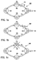
- Fig. 1a shows a schematic view of a communication ring network 100 where the present invention may be implemented.
- the network 100 has a number of N nodes 102-108 connected to each other by transmission links e.g. optical links 110.
- N stands for at least three, meaning that the network 100 consists of at least three nodes.
- the transmission links 110 comprised of; a first transmission link or working ring 112, and a second transmission link or a protection ring 114.
- the working ring 112 is carrying traffic in one transmission direction, clockwise in the figure.
- the protection ring 114 is carrying traffic in the opposite transmission direction, counter-clockwise in the figure.
- the traffic can, for example be electric, optical energy or wavelength channels.
- Fig. 1a also shows the communication network 100 in its normal working state, where the M optical channels are transmitted in one direction through the working ring 112 together with optical amplifier spontaneous emission (ASE). In the protection ring 114 it is only the ASE power that propagates, in the opposite direction to the working ring 112.
- This communication network 100 could be a wavelength division multiplexed self-healing ring communication network 100, as in Fig. 1a.
- Other types of networks are, for example wavelength division multiplexing (WDM) networks which are not shown here, could also be used as the communication network system.
- WDM wavelength division multiplexing
- Each node 102-108 in the communication network 100 can consist of an optical add/drop multiplexer 118, OADM, which is able to add/drop wavelength channels or traffic dedicated to the node, i.e. local traffic, and by-pass others. Some wavelength channels can be dedicated to a node, other wavelength channels will be passed by and go to the next node in the working ring 112.
- OADM optical add/drop multiplexer 118
- Fig. 1b shows the communication network 100 with link error, e.g. a cable cut, between node 102 and node 104.
- Protection actions have taken place within the nodes 102 and 104 themselves, without involving a network management system 116, which is merely informed at failure events.
- the protection actions are accomplished by the node, using electronics in a combination of signal on/off in the node itself at the working/protection rings 112, 114.
- the node 102 detects by itself when a link error, e.g. a cable cut occurs and it will by itself automatically divert the traffic on working ring 112 towards the protection ring 114. All traffic leaving the node 102 will then go back into the protection ring 114 and a tail node arises.
- link error e.g. a cable cut
- the node 104 also detects itself when a link error, e.g. a cable cut occurs and it will by itself automatically divert traffic from the protection ring 114 towards the working ring 112. All traffic leaving the node 104 will then go back into the working ring 112 and a head node arises.
- the nodes 106 and 108 will act as transit nodes which means that wavelength channels that normally are transmitted only on the working ring 112 also are transmitted on the protection ring 114, but just pass by the nodes 106 and 108 without any adding/dropping of any wavelength channels. When the transmitted wavelength channels return back to the node on the working ring 112 adding/dropping channels are working as normal at each node.
- link errors e.g. cable cuts
- the error e.g. cable cut occurs only in the working ring 112
- the other is when the error, e.g. cable cut occurs only in the protection ring 114.
- the error occurs on the working ring 112
- the first node 104 after the error in the traffic direction clockwise will automatically by itself change its mode of operation to a head node.
- the last node 102 before the error in the traffic direction clockwise will automatically by it self change its mode of operation to a tail node.
- an error e.g.
- the last node 102 before the error in the traffic direction will automatically by itself change its mode of operation to a tail node and the first node 104 after the error in the traffic direction will automatically by itself change its mode of operation to a head node.
- Fig. 1c shows the communication network 100 with a node failure.
- the same kind of re-configuration, i.e. change of mode of operation will occur as in Fig. 1b, so that one head node, the node 104, and one tail node, the node 108, will be established. Also in this case there is a transit node 106 in between the head node 104 and the tail node 108.
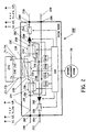
- Fig. 2 shows a block diagram of an optical add/drop multiplexer node 200 according to the invention, which node can be any of the nodes 102-108 in Fig. 1.
- the node 200 has a working ring input 202, which is connected to a first light propagating means, e.g. first incoming optical link 210 which could be an optical fiber.
- the working ring input 202 is connected to a first optical input 216 of an optical switching means, e.g. first optical switch 214, which can be switched for working in either bar or cross states.
- a second light propagation means, e.g second incoming optical link 220 which could be an optical fiber, is connected to a protection ring input 208 of the node 200.
- This protection ring input 208 is connected to a second optical input 218 of the first optical switch 214.
- a first optical output 230 of the first optical switch 214 which in bar state is coupled to the first optical input 216, is connected to a first optical input 228 of an optical channel selective switch or wavelength selective switch 226, which also works in either bar or cross state.
- the first optical input 228 of the channel selective switch 226 is coupled to a first optical output 244 of said channel selective switch 226 in bar state.
- This first optical output 244 is optically connected to an input 242 on a line terminal 274, which is associated with the node.
- An output 246 on the line terminal 274 is optically connected to a second input 248 of the channel selective switch 226.
- This second input 248 is in bar state connected to a second optical output 236 of said channel selective switch 226, which second optical output 236 is optically connected to a first input 234 of an optical switching means e.g. a second optical switch 232.
- the second optical switch 232 can operate in bar and cross states.
- a second input 238 of the second optical switch 232 is connected to a second output 240 of the first optical switch 214, which second output 240 is coupled to the second input 218 in bar state.
- a first output 250 of the second optical switch 232 which in bar state is coupled to the first input 234, is connected to an optical amplifier 260, which in turn is connected to a first optical breaking switch 264.
- This switch 264 is connected to a working ring output 206 in the node 200.
- the working ring output 206 is connected to a third light propagating means 270.
- a second output 252 of the second optical switch 232, which in bar state is coupled to the second input 238, is connected to a second optical amplifier 262, which in turn is connected to a second optical breaking switch 266.
- the second breaking switch 266 is connected to an protection ring output 204 in the node 200, which is connected to a fourth light propagating means 272.
- a first incoming link supervision means e.g. a first fault monitor 222 is optically connected to the first input 216 of the first optical switch 214.
- a second incoming link supervision means e.g. a second fault monitor 224 is optically coupled to the second input 218 of the first optical switch 214.
- a first power detection monitor 254 is optically coupled to the first output 250 of the second optical switch 232, and a second power detection monitor 256 is optically coupled to the second output 252 of the second optical switch 232.
- the fault monitors 222 and 224, the amplifiers 260 and 262, as well as the power detection monitors 254 and 256 are electrically connected to a control means or local control unit 258.
- the unit 258 controls the first and second optical switches 214 and 232, the wavelength selective switch 226, and the first and second breaking switches 264 and 266.
- the local control unit 258 is connected to a network management means, the so called network management system 116, which is located outside the node 200.
- the network management system is connected correspondingly to other nodes as well.
- the first light propagating means 210 connected to the working ring input 202 of the optical add/drop multiplexer node 200 forms with the third light propagation means 270, connected.to the working ring output 206, a part of the working ring 112, c.f. Fig. 1.
- the second light propagating means 222 connected to the protection ring input 208 of the optical add/drop multiplexer node 200 forms with the fourth light propagation means 272, connected to the protection ring output 204, a part of the protection ring 114, c.f. Fig. 1b.
- the optical add/drop multiplexer node 200 When the optical add/drop multiplexer node 200 is in normal working state (Fig. 1a) the number of M wavelength channels come into the node 200 from the working ring input 202 and they reach the wavelength selective switch 226 after being passed through the first optical switch 214 which is in bar state.
- the wavelength selective switch 226 performs the wavelength channels adding/dropping, i.e. the local traffic, and the wavelength channels that by-pass the node 200.
- the wavelength selective switch 226 selects and drops the wavelength channels dedicated to the node 200, towards the line terminal 274 at its input 242 (Rx).
- the line terminal 274 comprises an optical receiver connected to the input 242 via a filtering device, and a transmitter connected to the output 246.
- the line terminal 274 further comprises means for demodulating the modulated light (not shown) and means for converting the modulation to electrical signals (not shown), and, furthermore, means for conveying these electrical signals to dedicated receivers via electrical outputs.
- the line terminal 274 also receives, via electrical input, electrical signals containing information, which signals are to be sent to a receiver through the network 100.
- the electrical signals are converted to modulation of light with selected wavelength, which is sent to the transmitter for adding to the network 100.
- the network management system 116 communicates with the local control unit 258, via a standard interface.
- the local control unit 258 thereafter controls the wavelength selective switch 226 to obtain the requested selection.
- the wavelength selective switch 226 adds new local traffic, coming from the line terminal 274 at the output 246 (Tx).
- the network management system 116 can order which wavelength channels shall be added to the working ring 112.
- the wavelength selective switch 226 by-passes and equalizes all the wavelength channels not dedicated to the node.
- the adding wavelength channels and by-passing wavelength channels coming from the wavelength selective switch 226 pass through the second optical switch 232 in bar state, through the optical amplifier 260 (for example an Erbium-doped fiber amplifier, EDFA) to be amplified and through the optical breaking switch 264 to be put into the working ring output 206 to reach the following OADM node.
- the protection ring input 208 is connected to the protection ring output 204, which is obtained by the two optical switches 214 and 232 both being in bar states. This also allows for any optical power coming into the node protection ring input 208 to be simply amplified by the second optical amplifier 262, and transferred to the protection ring output 204.
- the wavelength channels coming into the optical add/drop multiplexer node 200 can have different power levels, and in order to avoid unbalanced channel power through the network 100 a power equalization of wavelength channels is needed in each node 200.
- a power equalization of wavelength channels is needed in each node 200.
- an amount of outgoing optical power is dropped by the power detection monitor 254, which measures the optical power levels.
- the optical power levels are sent to the local control unit 258, which calculates attenuation values for each wavelength channel, in order to obtain the equalization.
- the local control unit 258 sends the attenuation values to the wavelength selective switch 226 that selectively applies them to the respective channels.
- This invention relates to a network fault recovery by nodes when a link fails between two nodes, for example between the nodes 102 and 104, see Fig. 1b.
- a first fault event could be when both the working ring 112 and the protection ring 114 fails.
- the communication network 110 will then reconfigure with the help of the nodes 102 and 104 fail by themselves changing over to the head node mode, Fig. 1b, and the tail node mode, respectively.
- the optical add/drop multiplexer node 200 in Fig. 2 is equipped with the first fault monitor 222, which taps a small amount of the incoming optical power from the working ring input 202. This could be the wavelength channels and/or the ASE power.
- the local control unit 258 gets information from the first fault monitor 222, and if there is any optical power the first fault monitor 222 stays in its working state. If the working ring 112 has failed and there is no optical power on the first fault monitor 222 if changes traffic over to protection state. The ASE power can still be present in the protection ring 114.
- any detection of the traffic loss by the first fault monitor 222 initiates reconfiguration of the node 200 by the local control unit 258.
- the first fault monitor 222 or the local control unit 258 is put into protection state.
- the local control unit 258 switches the first optical switch 214 over from bar state to cross state.
- the first optical switch 214 in cross state means that the second optical input 218 of the first optical switch 214 and the first optical output 230 of the first optical switch 214 are connected to each other. This means that the ASE power and/or traffic on the protection ring 114 is diverted over to the working ring 112.
- the local control unit 258 will also open the second breaking switch 266, so that neither traffic nor ASE power can be supplied to the protection ring output 204 after change-over.
- the node 200 has now entered a head node mode as in Fig. 1b.
- the local control unit 258 communicates with the network management system 116 and informs that the node 104 has become a head node.
- a process to recover a head node from protection state to working state is initiated by the network management system 116, which communicates with the local control unit 258.
- the local control unit 258 then closes the second breaking switch 266, and turns on the second optical amplifier 262 so that optical power can reach the preceding node in traffic diversion (the tail node) if the link is fault free, e.g. the optical fiber is unbroken.
- the local control unit 258 checks whether the first fault monitor 222 senses any optical power from the working ring input 202. This power could be the wavelength channels and/or the ASE power. If the first fault monitor 222 detects optical power the node will go into working state.
- the first fault monitor 222 or the local control unit 258 is put into working state.
- the local control unit 258 switches the first optical switch 214 from cross state to bar state so that traffic can be received from the working ring input 202.
- the traffic can now go through the working ring input 202 to the working ring output 206, which means that the traffic on the working ring 112 is back.
- the local control unit 258 informs the network management system 116 that the node 104 has gone back to the working state. If the first fault monitor 222 does not detect any optical power it will stay in its protection state.
- the local control unit 258 After a certain time, for example 500 ms, the local control unit 258 turns off the second optical amplifier 262, opens the second breaking switch 266, and the recovery procedure is canceled. The local control unit 258 informs the network management system 116 that the recovery of the node 104 has been canceled.
- the optical add/drop multiplexer node 200 in Fig. 2 is equipped with the second fault monitor 224, which taps a small amount of the incoming optical power from the protection ring input 208. This could be the ASE power and/or the wavelength channels.
- the local control unit 258 gets information from the second fault monitor 224, and if there is any optical power the second fault monitor 224 stays in its working state. If the protection ring 114 has failed and there is no optical power on the second fault monitor 224 if changes traffic over to protection state. The ASE power can still be present in the working ring 112.
- any detection of the loss of ASE power or traffic by the second fault monitor 224 initiates reconfiguration of the node 200 by the local control unit 258.
- the second fault monitor 224 or the local control unit 258 is put into protection state.
- the local control unit 258 switches the second optical switch 232 over from bar state to cross state.
- the second optical switch 232 in cross state means that the first optical input 234 of the second optical switch 232 and the second optical output 252 of the second optical switch 232 are connected to each other. This means that the traffic on the working ring 112 is diverted over to the protection ring 114.
- the local control unit 258 will also open the first breaking switch 264 so that neither traffic nor ASE power can be supplied to the working ring output 202 after change-over.
- the node 200 has now entered a tail node mode as in Fig. 1b.
- the local control unit 258 communicates with the network management system and informs the network management system 116 that the node 102 has become a tail node.
- a process to recover a tail node from protection state to working state is initiated by the network management system 116, which communicates with the local control unit 258.
- the local control unit 258 then closes the first breaking switch 264 and turns on the first optical amplifier 260 so that optical power can reach the succeeding node after traffic diversion (the head node), if the link is fault fre, e.g. the optical fiber is unbroken.
- the local control unit 258 checks whether the second fault monitor 224 senses any optical power from the protection ring input 208. This power could be the wavelength channels and/or the ASE power. If the second fault monitor 224 detects optical power the node will go into working state.
- the second fault monitor 224 or the local control unit 258 is put into working state.
- the local control unit 258 switches the second optical switch 232 from cross state to bar state so that traffic can return to the working ring output 206.
- the traffic can now go through the working ring input 202 to the working ring output 206, which means that the traffic on the working ring 112 is back.
- the local control unit 258 informs the network management system 116 that the node 102 has returned to the working state. If the second fault monitor 224 does not detect any optical power it will stay in its protection state.
- the local control unit 258 turns off the first optical amplifier 260, opens the first breaking switch 264, and the recovery procedure is canceled.
- the local control unit 258 informs the network management system 116 that the recovery of the node 102 has been canceled.
- the traffic will go between head node 104 and tail node 102 in the communication network 100, they still detect optical energy, i.e. signals at both their fault monitors 222, 224 Fig 2, maintaining their normal configuration. This allows the network 100 to retain the normal functions for the working ring 112.
- the tail node 108 shortly divert all the wavelength channels from the working ring input 202 to the protection ring output 204.
- the head node 104 shortly divert all the wavelength channels from the protection ring input 208 to the working ring output 206.
- the traffic diversion by the tail node to the protection ring 114 reaches the head node, which divert back to working ring 112 and a loop is formed.
- the transit nodes 106, 108 are just nodes that are not head or tail nodes. They can add/drop wavelength channels, by-pass wavelength channels on the working ring 112 and/or the protection ring 114.
- a second fault event could be when only the working ring 112 fails. If the working ring 112 is faulty, e.g. broken, the first fault monitor 222 detects the signal loss and starts the node 104 reconfiguration into the head node, see first fault event, which opens the second breaking switch 266. This causes the signal loss at the second fault monitor 224 of the previous node 102 which then starts the reconfiguration of the node 102 into tail node, see first fault event, which opens the first breaking switch 264.
- a third fault event can be when only the protection ring 114 fails. If the protection ring 114 is faulty, e.g. broken, the individual node recovery actions would be the same but with an inverted order of sequence compared to the second fault event. This means that first the tail node and then the head node arises, obtaining the same node states and communication paths as the first fault event.
- This invention also relates to a fault recovery when a node, e.g. 102 fails, Fig 1c, with the same procedures as in the first fault event. The difference is that different nodes will become head node and tail node. In this fault event the node 104 will become the head node 104, see first fault event, and the node 108 will become the tail node 108, see first fault event. The faulty node 102 will be isolated from the others in Fig. 1c.
- Fig. 4 shows a block diagram of an alternative node 400 that can act as head node and/or tail node.
- the alternative node 400 can be any of the nodes 102-108 in Fig. 1, according to the invention.
- the alternative node 400 has the working ring input 202, which is connected to the first light propagating means 210, e.g. an optical fiber.
- the working ring input 202 is connected to a first optical input 404 of an optical switch or optical switching means 402, which can be switched for working in, e.g; bar state, first cross state and/or second cross states.
- the second light propagation means 220 which also could be an optical fiber, is connected to the protection ring input 208 of the node 400.
- This protection ring input 208 is connected to a second optical input 406 of the optical switch 402.
- the third light propagating means 270 is connected to the working ring output 206, which is connected to the first optical breaking switch 264.
- a second optical output 410 of the optical switch 402, which in bar state is coupled to the second optical input 406, is connected the second optical breaking switch 266.
- the fourth light propagating means 272 is connected to the protection ring output 204 which is connected to the second optical breaking switch 266.
- the first fault monitor 222 is optically connected to the first input 404 of the optical switch 402.
- the second fault monitor 224 is optically coupled to the second input 406 of the optical switch 402.
- the fault monitors 222, 224 and the optical switch 402 are electrically connected to the control means or local control unit 258, which controls the first and second breaking switches 264 and 266.
- the local control unit 258 is connected to the network management means or the network management system 116, which is located outside the node.
- the network management system 116 is connected correspondingly to other nodes as well.
- the number of M wavelength channels come into the node 400 from the working ring input 202, and they pass through the optical switch 402 which is in bar state.
- the local control unit 258 controls the optical switch 402, and communicates with the network management system 116 via a standard interface.
- the first light propagation means 210, and the working ring input 202 is connected to the third light propagation means 270 via the optical switch 402 in bar state, the first breaking switch 264, the working ring output 206, and forms part of the working ring 112, Fig. 1a.
- Fig. 1a As is also shown in Fig.
- the alternative node 400 can operate either as working node described above, as the head node, as the tail node or as transit node.
- the node 400 in Fig. 4 is equipped with the first fault monitor 222.
- the monitor 222 taps a small amount of the optical power from the working ring input 202. This could be the wavelength channels and/or ASE power.
- the local control unit 258 gets information from the first fault monitor 222, and if there is any optical power the fault monitor 222 stays in its working state. If the working ring 112 has failed the fault monitor 222 changes over to protection state. The ASE power can still be present in the protection ring 114. Any detection of the traffic loss by the first fault monitor 222 initiates reconfiguration of the node 400 by the local control unit 258.
- the first fault monitor 222 or the local control unit 258 is put in protection state. After fault detection the local control unit 258 switches the optical switch 402 to the first cross state.
- the first cross state means that second input 406 of the optical switch 402 and the first output 408 of the optical switch 402 are connected to each other. This means that the ASE power and/or traffic on the protection ring 114 is folded over to the working ring 112.
- the local control unit 258 will also open the second breaking switch 266 so that neither any traffic nor any ASE power can go to the protection ring output 204 after change-over.
- the node 400 has now entered a head node.
- the local control unit 258 communicates with the network management system 116 and informs that the node 104 has become the head node.
- the node 400 in Fig. 4 is equipped with the second fault monitor 224.
- the monitor 224 taps a small amount of the optical power from the protection ring input 208. This could be the ASE power and/or the wavelength channels.
- the local control unit 258 gets information from the second fault monitor 224, and if there is any optical power the fault monitor 224 stays in its working state. If the protection ring 114, has failed the fault monitor 224 changes over to protection state. The ASE power can still be present in the working ring 112. Any detection of the loss of traffic by the second fault monitor 224 initiates reconfiguration of the node 400 by the local control unit 258.
- the second fault monitor 224 or the local control unit 258 is put in protection state. After fault detection the local control unit 258 switches the optical switch 402 to the second cross state.
- the second cross state means that first input 404 of the optical switch 402 and the second output 410 of the optical switch 402 are connected to each other. This means that the traffic on the working ring 112 is folded over to the protection ring 114.
- the local control unit 258 will also open the first breaking switch 264 so that neither traffic nor ASE power can go to the working ring output 202 after change over.
- the node 400 will become a tail node.
- the local control unit 258 communicates with the network management system 116 and informs the network management system 116 that the node 102 has become tail node.
- the node 400 can work as head and tail nodes at the same time.
- the difference from above description is that the first and second breaking switches 264 and 266 are not open when node 400 is becoming the head and tail nodes. Traffic from head node is not in conflict with the traffic from the tail node due to the optical switch 402 that separates the different traffic directions from each other.
- Fig. 5a shows a schematic view of an alternative communication network, a bus communication network 500 embodying the present invention.
- the bus communication network 500 has the number of N nodes 502-508 connected to each other by bus transmission links, e.g.. bus optical links 510.
- bus transmission links 510 At one end there is a first node or a start node 502, which maybe designed like the nodes 200 or 400, and at the opposite end there is the Nth or an end node 508 which maybe designed like the node 200 or 400.
- the bus transmission links 510 comprise a first bus transmission link or working link 512 and a second bus transmission link or protection link 514.
- the bus communication network 500 is formed by the first node 502, the end node 508, the working link 512, and the protection link 514 together.
- the bus network 500 is transmitting the wavelength channels in one direction through the working link 512 and in the opposite direction through the protection link 514.
- Fig. 5a also shows the bus communication network 500 in its working state, which means those N wavelength channels together with a ASE power travelling in one direction through the working link 512 onto the protection link 514.
- This bus communication network 500 could also be a wavelength division multiplexed self-healing bus communication network. Other types of bus communication networks that are not shown here could be used as the bus communication network.
- Each node in the bus communication network 500 can consist of an optical add/drop multiplexer, which is able to add/drop wavelength channels of traffic dedicated to the node, i.e. local traffic, and by-pass others.
- Other nodes, such as in Fig. 4 can be used as head node, tail node or transit nodes.
- the bus communication network 500 is working as previously described.
- Fig. 5b shows examples of two places A and B where link failures, e.g. cable cuts could occur. The cable cut could be anywhere on the bus communication network.
- Each node after a cable cut will act as a head node and each node before a cable cut will act as a tail node, as previously described in connection with Fig. 2 and Fig. 4.
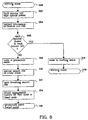
- Figure 6 shows the method for a node to become the head node 104, Fig. 1b, which is described earlier in this section.
- the main steps are as follows:
- Figure 7 shows the method for a node in protection state how to become normal node. This is earlier described in this section. The main steps are as follows:
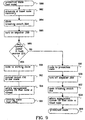
- Fig. 8 shows the method for a node to become the tail node, Fig. 1b. This is earlier described in this section. The main steps are as follows:
- Figure 9 shows a method for the node in protection state how to become normal node. This is earlier described in this section. The main steps are as follows:
- channel selective switch is not involved in the node reconfiguration process. This means it is not affected by any transient, where by the traffic routing and add/drop functions are stable during the node reconfiguration routine.
Landscapes
- Engineering & Computer Science (AREA)
- Computer Networks & Wireless Communication (AREA)
- Signal Processing (AREA)
- Small-Scale Networks (AREA)
- Optical Communication System (AREA)
- Time-Division Multiplex Systems (AREA)
Abstract
Description
- The present invention relates to an apparatus and a method for a communication network, more particular to a self-healing network.
- In a conventional self-healing ring architecture, synchronous digital hierarchy SDH or synchronous optical network SONET, utilizing add/drop multiplexer (ADM), the optical fiber is only used as point to point link and optical-electrical conversion is operated at each node. In such a ring the bottleneck is constituted by the speed of the processing electronics, and the bandwidth-sharing is characteristic for this architecture leads to a limitation of the network capacity.
- In the article "Self-Healing Ring Network Architecture Using WDM for Growth", ECOC 92, Tu P1.16, by Aly Elrefaie, is presented a self-healing ring network. It is described by a 2-fiber WDM ring network where N-1 local offices are originating traffic that is served by a single hub. Transmission on both fiber rings is identical except for the direction of propagation; the counter propagating signals facilitate the network survivability during a cable cut. Each of the N-1 local offices is assigned a unique wavelength for transmission to and receiving from the hub.
- In the PCT-application WO 93/00756, by Sandesara is described a self-healing bidirectional logical-ring network using crossconnects nodes. The network is partitioned into independent segments. Each segment consists of two or more nodes, interconnected with two transmission links working in different directions. When a failure occurs a crossconnect maintains a pre-selected pattern of interconnections between segments.
- In the above PCT-application WO 93/00756 is described a unidirectional self-healing network. In addition to the transmission link there is also a spare link. The transmitted signal is duplicated and flows in both said links at the same time. The destination node then selects the better of the two signals. It is also stated that the signal structure in previous known uni- and bidirectional networks consists of a predetermined number of subrate multiplexed channels operating at fixed rate.
- In the US patent US 5,003,531 is described a data communication network comprising a series of nodes connected by optical fiber links providing direct bidirectional communication between adjacent nodes. In the US patent head end nodes and tail end nodes has to be predefined. This introduces complexity in the Network Management System that must know if a node is a transient node, a head node or a tail node. From US-A-5159595, US-A-4633246, FR-A-2617354, and from the IEEE GLOBAL TELECOMMUNICATION CONFERENCE, Volume 3, and from IEEE TRANSACTIONS ON COMMUNICATIONS, Volume 40 is known a communication network system comprising nodes where each node comprises control means for controlling the nodes into one of the following modes:
- A normal mode where optical traffic is transmitted through a working ring.
- A head mode where traffic through the working ring is diverted back into a protection ring.
- A tail mode where optical traffic through a protection ring is diverted back into the working ring.
- This invention pays attention to the problem that it takes long time between detecting a fault and re-routing the traffic in a communication network, in particular a self-healing ring network. This invention also addresses the problem that a tremendous amount of traffic and data might become lost when an error occurs and the traffic has to be re-routed in the communication network.
- According to this invention, a communication node in a communication network can detect the fault easily and quickly, in that the detection takes place in the node itself.
- Furthermore, the node is able to detect a fault in the network that occurs in the immediate surrounding of this node. Upon detection of a fault the node is capable of swiftly re-routing any traffic and will, additionally, go from an active working state into a protection state. After error identification the node will self-heal, recuperate, and automatically go back into the working state
- The purpose of the invention is to get a self-healing network in which the nodes are rapidly self-healing.
- A further purpose is that the nodes need no network management for the healing.
- An advantage is that the node can add/drop any of the wavelengths for the local traffic and to by-pass others.
- Another advantage is that if a cable is cut or broken all traffic can swiftly be re-routed by the node itself, restoration takes place within the node local control system, without involving network management.
- Yet another advantage is that this invention shortens the time needed for the network to recover.
- Further advantage is that network restoration is fast in order to provide high quality service.
- The invention will be presented with the help of the best mode carrying out the invention characterized by the characterizing features set forth in the appended claims.
-
- Figure 1a shows a communication network system.
- Figure 1b shows a communication network system with links cut.
- Figure 1c shows a communication network system with node failure.
- Figure 2 shows a detailed node structure.
- Figure 3 shows a detailed head node, and a tail node.
- Figure 4 shows a modified node structure.
- Figure 5a shows a bus communication network system.
- Figure 5b shows a bus communication network system with links cut.
- Figure 6 shows a flow chart over a method for a node in working state to become head node.
- Figure 7 shows a flow chart over a method for a node in protection state to become normal node.
- Figure 8 shows a flow chart over a method for a node in working state to become tail node.
- Figure 9 shows a flow chart over a method for a node in protection state to become normal node.
-
- Fig. 1a shows a schematic view of a
communication ring network 100 where the present invention may be implemented. Thenetwork 100 has a number of N nodes 102-108 connected to each other by transmission links e.g.optical links 110. N stands for at least three, meaning that thenetwork 100 consists of at least three nodes. Thetransmission links 110 comprised of; a first transmission link or workingring 112, and a second transmission link or aprotection ring 114. The workingring 112 is carrying traffic in one transmission direction, clockwise in the figure. Theprotection ring 114 is carrying traffic in the opposite transmission direction, counter-clockwise in the figure. The traffic can, for example be electric, optical energy or wavelength channels. If wavelength channels are used, there are M optical channels transmitted where M can be less, equal or more than N nodes. Fig. 1a also shows thecommunication network 100 in its normal working state, where the M optical channels are transmitted in one direction through the workingring 112 together with optical amplifier spontaneous emission (ASE). In theprotection ring 114 it is only the ASE power that propagates, in the opposite direction to the workingring 112. Thiscommunication network 100 could be a wavelength division multiplexed self-healingring communication network 100, as in Fig. 1a. Other types of networks are, for example wavelength division multiplexing (WDM) networks which are not shown here, could also be used as the communication network system. Each node 102-108 in thecommunication network 100 can consist of an optical add/drop multiplexer 118, OADM, which is able to add/drop wavelength channels or traffic dedicated to the node, i.e. local traffic, and by-pass others. Some wavelength channels can be dedicated to a node, other wavelength channels will be passed by and go to the next node in the workingring 112. - Fig. 1b shows the
communication network 100 with link error, e.g. a cable cut, betweennode 102 andnode 104. Protection actions have taken place within thenodes network management system 116, which is merely informed at failure events. The protection actions are accomplished by the node, using electronics in a combination of signal on/off in the node itself at the working/protection rings 112, 114. Thenode 102 detects by itself when a link error, e.g. a cable cut occurs and it will by itself automatically divert the traffic on workingring 112 towards theprotection ring 114. All traffic leaving thenode 102 will then go back into theprotection ring 114 and a tail node arises. Thenode 104 also detects itself when a link error, e.g. a cable cut occurs and it will by itself automatically divert traffic from theprotection ring 114 towards the workingring 112. All traffic leaving thenode 104 will then go back into the workingring 112 and a head node arises. Thenodes ring 112 also are transmitted on theprotection ring 114, but just pass by thenodes ring 112 adding/dropping channels are working as normal at each node. - There are actually at least two types of link errors, e.g. cable cuts; one is when the error, e.g. cable cut occurs only in the working
ring 112, and the other is when the error, e.g. cable cut occurs only in theprotection ring 114. When the error occurs on the workingring 112, thefirst node 104 after the error in the traffic direction clockwise will automatically by itself change its mode of operation to a head node. Thelast node 102 before the error in the traffic direction clockwise will automatically by it self change its mode of operation to a tail node. In the second case, when an error, e.g. a cable cut occurs in theprotection ring 114, thelast node 102 before the error in the traffic direction will automatically by itself change its mode of operation to a tail node and thefirst node 104 after the error in the traffic direction will automatically by itself change its mode of operation to a head node. - Fig. 1c shows the
communication network 100 with a node failure. The same kind of re-configuration, i.e. change of mode of operation will occur as in Fig. 1b, so that one head node, thenode 104, and one tail node, thenode 108, will be established. Also in this case there is atransit node 106 in between thehead node 104 and thetail node 108. - Fig. 2 shows a block diagram of an optical add/
drop multiplexer node 200 according to the invention, which node can be any of the nodes 102-108 in Fig. 1. Thenode 200 has a workingring input 202, which is connected to a first light propagating means, e.g. first incomingoptical link 210 which could be an optical fiber. The workingring input 202 is connected to a firstoptical input 216 of an optical switching means, e.g. firstoptical switch 214, which can be switched for working in either bar or cross states. A second light propagation means, e.g second incomingoptical link 220 which could be an optical fiber, is connected to aprotection ring input 208 of thenode 200. Thisprotection ring input 208 is connected to a secondoptical input 218 of the firstoptical switch 214. A firstoptical output 230 of the firstoptical switch 214, which in bar state is coupled to the firstoptical input 216, is connected to a firstoptical input 228 of an optical channel selective switch or wavelengthselective switch 226, which also works in either bar or cross state. The firstoptical input 228 of the channelselective switch 226 is coupled to a firstoptical output 244 of said channelselective switch 226 in bar state. This firstoptical output 244 is optically connected to aninput 242 on aline terminal 274, which is associated with the node. Anoutput 246 on theline terminal 274 is optically connected to asecond input 248 of the channelselective switch 226. Thissecond input 248 is in bar state connected to a secondoptical output 236 of said channelselective switch 226, which secondoptical output 236 is optically connected to afirst input 234 of an optical switching means e.g. a secondoptical switch 232. The secondoptical switch 232 can operate in bar and cross states. Asecond input 238 of the secondoptical switch 232 is connected to asecond output 240 of the firstoptical switch 214, whichsecond output 240 is coupled to thesecond input 218 in bar state. - A
first output 250 of the secondoptical switch 232, which in bar state is coupled to thefirst input 234, is connected to anoptical amplifier 260, which in turn is connected to a first optical breakingswitch 264. Thisswitch 264 is connected to a workingring output 206 in thenode 200. The workingring output 206 is connected to a thirdlight propagating means 270. Asecond output 252 of the secondoptical switch 232, which in bar state is coupled to thesecond input 238, is connected to a secondoptical amplifier 262, which in turn is connected to a second optical breakingswitch 266. Thesecond breaking switch 266 is connected to anprotection ring output 204 in thenode 200, which is connected to a fourthlight propagating means 272. - A first incoming link supervision means, e.g. a
first fault monitor 222 is optically connected to thefirst input 216 of the firstoptical switch 214. A second incoming link supervision means, e.g. asecond fault monitor 224 is optically coupled to thesecond input 218 of the firstoptical switch 214. A firstpower detection monitor 254 is optically coupled to thefirst output 250 of the secondoptical switch 232, and a secondpower detection monitor 256 is optically coupled to thesecond output 252 of the secondoptical switch 232. The fault monitors 222 and 224, theamplifiers local control unit 258. Theunit 258 controls the first and secondoptical switches selective switch 226, and the first and second breaking switches 264 and 266. Thelocal control unit 258 is connected to a network management means, the so callednetwork management system 116, which is located outside thenode 200. The network management system is connected correspondingly to other nodes as well. - The first light propagating means 210 connected to the working
ring input 202 of the optical add/drop multiplexer node 200 forms with the third light propagation means 270, connected.to the workingring output 206, a part of the workingring 112, c.f. Fig. 1. In Fig. 2 the second light propagating means 222 connected to theprotection ring input 208 of the optical add/drop multiplexer node 200 forms with the fourth light propagation means 272, connected to theprotection ring output 204, a part of theprotection ring 114, c.f. Fig. 1b. - When the optical add/
drop multiplexer node 200 is in normal working state (Fig. 1a) the number of M wavelength channels come into thenode 200 from the workingring input 202 and they reach the wavelengthselective switch 226 after being passed through the firstoptical switch 214 which is in bar state. The wavelengthselective switch 226 performs the wavelength channels adding/dropping, i.e. the local traffic, and the wavelength channels that by-pass thenode 200. The wavelengthselective switch 226 selects and drops the wavelength channels dedicated to thenode 200, towards theline terminal 274 at its input 242 (Rx). Theline terminal 274 comprises an optical receiver connected to theinput 242 via a filtering device, and a transmitter connected to theoutput 246. Theline terminal 274 further comprises means for demodulating the modulated light (not shown) and means for converting the modulation to electrical signals (not shown), and, furthermore, means for conveying these electrical signals to dedicated receivers via electrical outputs. Theline terminal 274 also receives, via electrical input, electrical signals containing information, which signals are to be sent to a receiver through thenetwork 100. The electrical signals are converted to modulation of light with selected wavelength, which is sent to the transmitter for adding to thenetwork 100. Thenetwork management system 116 communicates with thelocal control unit 258, via a standard interface. Thelocal control unit 258 thereafter controls the wavelengthselective switch 226 to obtain the requested selection. The wavelengthselective switch 226 adds new local traffic, coming from theline terminal 274 at the output 246 (Tx). Thenetwork management system 116 can order which wavelength channels shall be added to the workingring 112. The wavelengthselective switch 226 by-passes and equalizes all the wavelength channels not dedicated to the node. The adding wavelength channels and by-passing wavelength channels coming from the wavelengthselective switch 226 pass through the secondoptical switch 232 in bar state, through the optical amplifier 260 (for example an Erbium-doped fiber amplifier, EDFA) to be amplified and through theoptical breaking switch 264 to be put into the workingring output 206 to reach the following OADM node. As shown in Fig. 2 theprotection ring input 208 is connected to theprotection ring output 204, which is obtained by the twooptical switches protection ring input 208 to be simply amplified by the secondoptical amplifier 262, and transferred to theprotection ring output 204. - The wavelength channels coming into the optical add/
drop multiplexer node 200 can have different power levels, and in order to avoid unbalanced channel power through the network 100 a power equalization of wavelength channels is needed in eachnode 200. In order to accomplish such a function an amount of outgoing optical power is dropped by thepower detection monitor 254, which measures the optical power levels. The optical power levels are sent to thelocal control unit 258, which calculates attenuation values for each wavelength channel, in order to obtain the equalization. Thelocal control unit 258 sends the attenuation values to the wavelengthselective switch 226 that selectively applies them to the respective channels. - This invention relates to a network fault recovery by nodes when a link fails between two nodes, for example between the
nodes
A first fault event could be when both the workingring 112 and theprotection ring 114 fails. Thecommunication network 110 will then reconfigure with the help of thenodes - In order to discover an error, e.g. break, of the first transmission link or working
ring 112 the optical add/drop multiplexer node 200 in Fig. 2 is equipped with thefirst fault monitor 222, which taps a small amount of the incoming optical power from the workingring input 202. This could be the wavelength channels and/or the ASE power. Thelocal control unit 258 gets information from thefirst fault monitor 222, and if there is any optical power thefirst fault monitor 222 stays in its working state. If the workingring 112 has failed and there is no optical power on thefirst fault monitor 222 if changes traffic over to protection state. The ASE power can still be present in theprotection ring 114. Any detection of the traffic loss by thefirst fault monitor 222 initiates reconfiguration of thenode 200 by thelocal control unit 258. Thefirst fault monitor 222 or thelocal control unit 258 is put into protection state. After knowledge of fault detection by thefirst fault monitor 222 thelocal control unit 258 switches the firstoptical switch 214 over from bar state to cross state. The firstoptical switch 214 in cross state means that the secondoptical input 218 of the firstoptical switch 214 and the firstoptical output 230 of the firstoptical switch 214 are connected to each other. This means that the ASE power and/or traffic on theprotection ring 114 is diverted over to the workingring 112. Thelocal control unit 258 will also open thesecond breaking switch 266, so that neither traffic nor ASE power can be supplied to theprotection ring output 204 after change-over. Thenode 200 has now entered a head node mode as in Fig. 1b. Thelocal control unit 258 communicates with thenetwork management system 116 and informs that thenode 104 has become a head node. - A process to recover a head node from protection state to working state is initiated by the
network management system 116, which communicates with thelocal control unit 258. In order to the recovery procedure from the head node. Thelocal control unit 258 then closes thesecond breaking switch 266, and turns on the secondoptical amplifier 262 so that optical power can reach the preceding node in traffic diversion (the tail node) if the link is fault free, e.g. the optical fiber is unbroken. Thelocal control unit 258 checks whether thefirst fault monitor 222 senses any optical power from the workingring input 202. This power could be the wavelength channels and/or the ASE power. If thefirst fault monitor 222 detects optical power the node will go into working state. Thefirst fault monitor 222 or thelocal control unit 258 is put into working state. Thelocal control unit 258 switches the firstoptical switch 214 from cross state to bar state so that traffic can be received from the workingring input 202. The traffic can now go through the workingring input 202 to the workingring output 206, which means that the traffic on the workingring 112 is back. ASE power from theprotection ring input 204 toprotection ring output 208. Thelocal control unit 258 informs thenetwork management system 116 that thenode 104 has gone back to the working state. If thefirst fault monitor 222 does not detect any optical power it will stay in its protection state. After a certain time, for example 500 ms, thelocal control unit 258 turns off the secondoptical amplifier 262, opens thesecond breaking switch 266, and the recovery procedure is canceled. Thelocal control unit 258 informs thenetwork management system 116 that the recovery of thenode 104 has been canceled. - In order to discover an error, e.g. break of the second transmission link or
protection ring 112 the optical add/drop multiplexer node 200 in Fig. 2 is equipped with thesecond fault monitor 224, which taps a small amount of the incoming optical power from theprotection ring input 208. This could be the ASE power and/or the wavelength channels. Thelocal control unit 258 gets information from thesecond fault monitor 224, and if there is any optical power thesecond fault monitor 224 stays in its working state. If theprotection ring 114 has failed and there is no optical power on thesecond fault monitor 224 if changes traffic over to protection state. The ASE power can still be present in the workingring 112. Any detection of the loss of ASE power or traffic by thesecond fault monitor 224 initiates reconfiguration of thenode 200 by thelocal control unit 258. Thesecond fault monitor 224 or thelocal control unit 258 is put into protection state. After knowledge of fault detection by thesecond fault monitor 224 thelocal control unit 258 switches the secondoptical switch 232 over from bar state to cross state. The secondoptical switch 232 in cross state means that the firstoptical input 234 of the secondoptical switch 232 and the secondoptical output 252 of the secondoptical switch 232 are connected to each other. This means that the traffic on the workingring 112 is diverted over to theprotection ring 114. - The
local control unit 258 will also open thefirst breaking switch 264 so that neither traffic nor ASE power can be supplied to the workingring output 202 after change-over. Thenode 200 has now entered a tail node mode as in Fig. 1b. Thelocal control unit 258 communicates with the network management system and informs thenetwork management system 116 that thenode 102 has become a tail node. - A process to recover a tail node from protection state to working state is initiated by the
network management system 116, which communicates with thelocal control unit 258. In order to the recovery procedure from the tail node. Thelocal control unit 258 then closes thefirst breaking switch 264 and turns on the firstoptical amplifier 260 so that optical power can reach the succeeding node after traffic diversion (the head node), if the link is fault fre, e.g. the optical fiber is unbroken. Thelocal control unit 258 checks whether thesecond fault monitor 224 senses any optical power from theprotection ring input 208. This power could be the wavelength channels and/or the ASE power. If thesecond fault monitor 224 detects optical power the node will go into working state. thesecond fault monitor 224 or thelocal control unit 258 is put into working state. Thelocal control unit 258 switches the secondoptical switch 232 from cross state to bar state so that traffic can return to the workingring output 206. The traffic can now go through the workingring input 202 to the workingring output 206, which means that the traffic on the workingring 112 is back. ASE power from theprotection ring input 204 to theprotection ring output 208. Thelocal control unit 258 informs thenetwork management system 116 that thenode 102 has returned to the working state. If thesecond fault monitor 224 does not detect any optical power it will stay in its protection state. After a certain time, for example 500 ms, thelocal control unit 258 turns off the firstoptical amplifier 260, opens thefirst breaking switch 264, and the recovery procedure is canceled. Thelocal control unit 258 informs thenetwork management system 116 that the recovery of thenode 102 has been canceled. - Despite the link error between
node 102 and thenode 104 no traffic is lost. The traffic will go betweenhead node 104 andtail node 102 in thecommunication network 100, they still detect optical energy, i.e. signals at both their fault monitors 222, 224 Fig 2, maintaining their normal configuration. This allows thenetwork 100 to retain the normal functions for the workingring 112. Thetail node 108 shortly divert all the wavelength channels from the workingring input 202 to theprotection ring output 204. Thehead node 104 shortly divert all the wavelength channels from theprotection ring input 208 to the workingring output 206. The traffic diversion by the tail node to theprotection ring 114 reaches the head node, which divert back to workingring 112 and a loop is formed. There could be at least one node in between head and tail nodes, in this case working astransit nodes transit nodes ring 112 and/or theprotection ring 114. - In Fig. 3a, a second fault event could be when only the working
ring 112 fails. If the workingring 112 is faulty, e.g. broken, thefirst fault monitor 222 detects the signal loss and starts thenode 104 reconfiguration into the head node, see first fault event, which opens thesecond breaking switch 266. This causes the signal loss at the second fault monitor 224 of theprevious node 102 which then starts the reconfiguration of thenode 102 into tail node, see first fault event, which opens thefirst breaking switch 264. - In Fig. 3b, a third fault event can be when only the
protection ring 114 fails. If theprotection ring 114 is faulty, e.g. broken, the individual node recovery actions would be the same but with an inverted order of sequence compared to the second fault event. This means that first the tail node and then the head node arises, obtaining the same node states and communication paths as the first fault event. - This invention also relates to a fault recovery when a node, e.g. 102 fails, Fig 1c, with the same procedures as in the first fault event. The difference is that different nodes will become head node and tail node. In this fault event the
node 104 will become thehead node 104, see first fault event, and thenode 108 will become thetail node 108, see first fault event. Thefaulty node 102 will be isolated from the others in Fig. 1c. - The process to recover any fault events described above is done in the same way as to recover the head node from protection state, and recover the tail node from protection state.
- Fig. 4 shows a block diagram of an
alternative node 400 that can act as head node and/or tail node. Thealternative node 400 can be any of the nodes 102-108 in Fig. 1, according to the invention. Thealternative node 400 has the workingring input 202, which is connected to the firstlight propagating means 210, e.g. an optical fiber. The workingring input 202 is connected to a firstoptical input 404 of an optical switch or optical switching means 402, which can be switched for working in, e.g; bar state, first cross state and/or second cross states. The second light propagation means 220, which also could be an optical fiber, is connected to theprotection ring input 208 of thenode 400. Thisprotection ring input 208 is connected to a secondoptical input 406 of theoptical switch 402. A firstoptical output 408 of theoptical switch 402, which in bar state is coupled to the firstoptical input 404, is connected to the first optical breakingswitch 264. The thirdlight propagating means 270 is connected to the workingring output 206, which is connected to the first optical breakingswitch 264. A secondoptical output 410 of theoptical switch 402, which in bar state is coupled to the secondoptical input 406, is connected the second optical breakingswitch 266. The fourthlight propagating means 272 is connected to theprotection ring output 204 which is connected to the second optical breakingswitch 266. Thefirst fault monitor 222 is optically connected to thefirst input 404 of theoptical switch 402. Thesecond fault monitor 224 is optically coupled to thesecond input 406 of theoptical switch 402. The fault monitors 222, 224 and theoptical switch 402 are electrically connected to the control means orlocal control unit 258, which controls the first and second breaking switches 264 and 266. Thelocal control unit 258 is connected to the network management means or thenetwork management system 116, which is located outside the node. Thenetwork management system 116 is connected correspondingly to other nodes as well. - When the
alternative node 400 is in working state, as shown in Fig. 1a, the number of M wavelength channels come into thenode 400 from the workingring input 202, and they pass through theoptical switch 402 which is in bar state. Thelocal control unit 258 controls theoptical switch 402, and communicates with thenetwork management system 116 via a standard interface. As shown in Fig. 4, the first light propagation means 210, and the workingring input 202 is connected to the third light propagation means 270 via theoptical switch 402 in bar state, thefirst breaking switch 264, the workingring output 206, and forms part of the workingring 112, Fig. 1a. As is also shown in Fig. 4 the second light propagation means 220 and connected toprotection ring input 208 connected to second light propagation means 220 via theoptical switch 402 in bar state, thesecond breaking switch 266, theprotection ring output 204, forming part of theprotection ring 114 as shown in Fig. 1a. - The
alternative node 400 can operate either as working node described above, as the head node, as the tail node or as transit node. - In order to discover an error, e.g. break, in the first transmission link or working ring, the
node 400 in Fig. 4 is equipped with thefirst fault monitor 222. Themonitor 222 taps a small amount of the optical power from the workingring input 202. This could be the wavelength channels and/or ASE power. Thelocal control unit 258 gets information from thefirst fault monitor 222, and if there is any optical power the fault monitor 222 stays in its working state. If the workingring 112 has failed the fault monitor 222 changes over to protection state. The ASE power can still be present in theprotection ring 114. Any detection of the traffic loss by thefirst fault monitor 222 initiates reconfiguration of thenode 400 by thelocal control unit 258. Thefirst fault monitor 222 or thelocal control unit 258 is put in protection state. After fault detection thelocal control unit 258 switches theoptical switch 402 to the first cross state. The first cross state means thatsecond input 406 of theoptical switch 402 and thefirst output 408 of theoptical switch 402 are connected to each other. This means that the ASE power and/or traffic on theprotection ring 114 is folded over to the workingring 112. Thelocal control unit 258 will also open thesecond breaking switch 266 so that neither any traffic nor any ASE power can go to theprotection ring output 204 after change-over. Thenode 400 has now entered a head node. Thelocal control unit 258 communicates with thenetwork management system 116 and informs that thenode 104 has become the head node. - Recovery process of the head node is done the same way as described before. The difference is that the
optical switch 402 will return to the bar state which means that the firstoptical input 404 of theoptical switch 402 is coupled to the firstoptical output 408 of theoptical switch 402. - In order to discover an error, e.g. break of the second transmission link or protection ring, the
node 400 in Fig. 4 is equipped with thesecond fault monitor 224. Themonitor 224 taps a small amount of the optical power from theprotection ring input 208. This could be the ASE power and/or the wavelength channels. Thelocal control unit 258 gets information from thesecond fault monitor 224, and if there is any optical power the fault monitor 224 stays in its working state. If theprotection ring 114, has failed the fault monitor 224 changes over to protection state. The ASE power can still be present in the workingring 112. Any detection of the loss of traffic by thesecond fault monitor 224 initiates reconfiguration of thenode 400 by thelocal control unit 258. Thesecond fault monitor 224 or thelocal control unit 258 is put in protection state. After fault detection thelocal control unit 258 switches theoptical switch 402 to the second cross state. The second cross state means thatfirst input 404 of theoptical switch 402 and thesecond output 410 of theoptical switch 402 are connected to each other. This means that the traffic on the workingring 112 is folded over to theprotection ring 114. Thelocal control unit 258 will also open thefirst breaking switch 264 so that neither traffic nor ASE power can go to the workingring output 202 after change over. Thenode 400 will become a tail node. Thelocal control unit 258 communicates with thenetwork management system 116 and informs thenetwork management system 116 that thenode 102 has become tail node. - Recovery process of the head node is done the same way as described before. The only difference is that the
optical switch 402 will return to the bar state which means that the secondoptical input 406 of theoptical switch 402 is coupled to the secondoptical output 410 of theoptical switch 402. - The
node 400 can work as head and tail nodes at the same time. The difference from above description is that the first and second breaking switches 264 and 266 are not open whennode 400 is becoming the head and tail nodes. Traffic from head node is not in conflict with the traffic from the tail node due to theoptical switch 402 that separates the different traffic directions from each other. - Fig. 5a shows a schematic view of an alternative communication network, a
bus communication network 500 embodying the present invention. Thebus communication network 500 has the number of N nodes 502-508 connected to each other by bus transmission links, e.g.. busoptical links 510. At one end there is a first node or astart node 502, which maybe designed like thenodes end node 508 which maybe designed like thenode bus transmission links 510 comprise a first bus transmission link or working link 512 and a second bus transmission link or protection link 514. At thestart node 502 the working link 512 is in contact with the protection link 514, and thenode 502 acts as the tail node, see first fault event. At theend node 508 the protection link 514 is in contact with the working link 512 and thenode 508 acts as the head node, see first fault event. Thebus communication network 500 is formed by thefirst node 502, theend node 508, the working link 512, and the protection link 514 together. Thebus network 500 is transmitting the wavelength channels in one direction through the working link 512 and in the opposite direction through the protection link 514. Fig. 5a also shows thebus communication network 500 in its working state, which means those N wavelength channels together with a ASE power travelling in one direction through the working link 512 onto the protection link 514. Thisbus communication network 500 could also be a wavelength division multiplexed self-healing bus communication network. Other types of bus communication networks that are not shown here could be used as the bus communication network. Each node in thebus communication network 500 can consist of an optical add/drop multiplexer, which is able to add/drop wavelength channels of traffic dedicated to the node, i.e. local traffic, and by-pass others. Other nodes, such as in Fig. 4 can be used as head node, tail node or transit nodes. Thebus communication network 500 is working as previously described.
Fig. 5b shows examples of two places A and B where link failures, e.g. cable cuts could occur. The cable cut could be anywhere on the bus communication network. Each node after a cable cut will act as a head node and each node before a cable cut will act as a tail node, as previously described in connection with Fig. 2 and Fig. 4. - Figure 6 shows the method for a node to become the
head node 104, Fig. 1b, which is described earlier in this section. The main steps are as follows: - working state, block 600
- fault monitor 222 taps optical power, block 602
- tapped information to control
unit 258, block 604 - any optical power in fault monitor 222 ?, block 606
- node to protection state, block 608
-
optical switch 214 to cross state, block 610 - open breaking
switch 266, block 612 - inform
management system 116 that node is head node, block 614 - protection state (head node), block 616.
- working state, block 620
- Figure 7 shows the method for a node in protection state how to become normal node. This is earlier described in this section. The main steps are as follows:
- protection state (head node), block 700
- initiation of head node recovery, block 702
- close breaking
switch 266, block 704 - turn on
amplifier 262, block 706 - any optical power in fault monitor 222 ?, block 708
- node to working state, block 710
-
optical switch 214 to bar state, block 712 - inform
management system 116 that node is normal, block 714 - working state, block 716
- turn off
amplifier 262, block 720 - open breaking
switch 266,lock 722 - inform
management system 116 that node is head node, block 724 - protection state (head node), block 726
- Fig. 8 shows the method for a node to become the tail node, Fig. 1b. This is earlier described in this section. The main steps are as follows:
- working state, block 800
- fault monitor 224 taps optical power, block 802
- tapped information to control
unit 258, block 804 - any optical power in fault monitor 224 ?, block 806
- node to protection state, block 808
-
optical switch 232 to cross state, block 810 - open breaking
switch 264, block 812 - inform
management system 116 that node is tail node, block 814 - protection state (tail node), block 816.
- working state, block 820
- Figure 9 shows a method for the node in protection state how to become normal node. This is earlier described in this section. The main steps are as follows:
- protection state (tail node), block 900
- initiation of tail node recovery, block 902
- close breaking
switch 264, block 904 - turn on
amplifier 260, block 906 - any optical power in fault monitor 224 ?, block 908
- node to working state, block 910
-
optical switch 232 to bar state, block 912 - inform
management system 116 that node is normal, block 914 - working state, block 916
- turn off
amplifier 260, block 920 - open breaking
switch 264, block 922 - inform
management system 116 that node is tail node, block 924 - protection state (tail node), block 926
- Advantage is that the channel selective switch is not involved in the node reconfiguration process. This means it is not affected by any transient, where by the traffic routing and add/drop functions are stable during the node reconfiguration routine.
- The invention described above is described in an optical solution but this is not a necessary requirement.
Claims (7)
- A communication network system (100, 500) comprising at least three nodes (200, 400) which are interconnected by a working ring and a protection ring transmitting traffic in opposite directions between the nodes, each of the nodes comprising:first incoming link supervision means (222) for detecting incoming optical energy from a first incoming optical link (210);second incoming link supervision means (224) for detecting incoming optical energy from a second incoming optical link (220);optical switching means (214, 232, 402) for switching incoming optical energy from the first or the second optical incoming link to a first or a second optical outgoing link, whereby the first incoming and the first outgoing links are connected to the working ring, and whereby the second incoming and the second outgoing links are connected to the protection ring;control means (258) connected to the supervision means and switching means for controlling the node into one of the following modes in response to the detection of incoming optical energy on one or both of the incoming optical links:a normal mode where optical traffic is transmitted through the working ring; anda protection mode consisting of a head mode where optical traffic through the working ring is diverted back into the protection ring and a tail mode where optical traffic through the protection ring is diverted back into the working ring;the control means being arranged such that when detecting a fault by loss of incoming optical power, the node goes to protection mode and changes the states of the optical switching means (214, 232, 402), so that a transmission loop is created using both the working ring and the protection ring, without passing the fault; characterized byrecovery means to initiate a recovery test by creating a test loop passing the fault when the node is in protection mode;means to influence the node to stay in protection mode, when detecting no optical power in the test loop; andmeans to influence the node to go to normal mode and change state of optical switching means, so that signals are once again transmitted in the working ring, when detecting optical power in the test loop.
- A communication network system according to claim 1, wherein the recovery means comprise breaking switches adapted to create a separate test loop for the recovery testing, and wherein the control means is adapted to control the node from head or tail mode into normal mode such that optical energy is forwarded from the first incoming link to the first outgoing link and optical energy from the second incoming link to the second outgoing link.
- A communication network system according to claim 1, wherein the control means is adapted to control the node into a tail mode when the link supervision means detect incoming energy from the first, but not the second incoming links such that optical energy is forwarded from the first incoming link to the second outgoing link, but not to the first outgoing link.
- A communication network system according to claim 1 wherein the control means is adapted to control the node into a head mode when the link supervision means detect incoming energy from the second but not the first incoming links such that optical energy is forwarded from the second incoming link to the first outgoing link, but not to the second outgoing link.
- A network system according to any of claims 1 to 4 wherein:the first incoming and outgoing links are connected to separate other nodes to constitute part of the working ring; andthe second incoming and outgoing links are connected to separate nodes to constitute part of the protection ring.
- A method for restoring a communication network system (100, 500) of at least three nodes (200, 400), the nodes being interconnected by a working ring and a protection ring, each node comprising a working ring input (202) and a working ring output (206) connected to the working ring (112, 512), and further comprising a protection ring input (204) and a protection ring output (208) connected to the protection ring (114, 514), where the working and protection ring can transmit signals in opposite directions, the method comprising the following steps;
all nodes in the system being in a normal mode, wherein signals are being transmitted in the working ring;
when detecting a fault by loss of incoming optical power, some nodes go to a protection mode and change the states of optical switching means (214, 232, 402), so that a transmission loop is created using both the working ring and the protection ring, said transmission loop not passing the fault; characterised by:initiating a recovery test by creating a test loop passing the fault, said test loop being separate from the transmission loop, which recovery test is initiated by the nodes who are in protection mode;when detecting no optical power in the test loop, the nodes stay in protection mode;when detecting optical power in the test loop, the nodes go to normal mode and change state of optical switching means, so that signals are once again transmitted on the working ring; andinforming a management system about node status. - , A method according to claim 6, wherein the test loop is being created by closing breaking switches (264, 266), which breaking switches are otherwise open during protection mode.
Applications Claiming Priority (5)
| Application Number | Priority Date | Filing Date | Title |
|---|---|---|---|
| SE9502310A SE506713C2 (en) | 1995-06-26 | 1995-06-26 | Device and method of optical self-healing network |
| SE9502310 | 1995-06-26 | ||
| SE9503573A SE9503573D0 (en) | 1995-10-12 | 1995-10-12 | Self-healing network |
| SE9503573 | 1995-10-12 | ||
| PCT/SE1996/000794 WO1997001907A1 (en) | 1995-06-26 | 1996-06-18 | Self-healing network |
Publications (2)
| Publication Number | Publication Date |
|---|---|
| EP0878079A1 EP0878079A1 (en) | 1998-11-18 |
| EP0878079B1 true EP0878079B1 (en) | 2005-04-13 |
Family
ID=26662328
Family Applications (1)
| Application Number | Title | Priority Date | Filing Date |
|---|---|---|---|
| EP96922318A Expired - Lifetime EP0878079B1 (en) | 1995-06-26 | 1996-06-18 | Self-healing network |
Country Status (9)
| Country | Link |
|---|---|
| US (1) | US6088141A (en) |
| EP (1) | EP0878079B1 (en) |
| JP (1) | JPH11508427A (en) |
| CN (1) | CN1094007C (en) |
| AU (1) | AU6322696A (en) |
| BR (1) | BR9608792A (en) |
| DE (1) | DE69634611T2 (en) |
| ES (1) | ES2239333T3 (en) |
| WO (1) | WO1997001907A1 (en) |
Families Citing this family (96)
| Publication number | Priority date | Publication date | Assignee | Title |
|---|---|---|---|---|
| TW353838B (en) * | 1996-11-12 | 1999-03-01 | Toshiba Corp | Ring network system and control method of its communication path |
| JPH10247878A (en) * | 1997-03-04 | 1998-09-14 | Kokusai Denshin Denwa Co Ltd <Kdd> | Optical transmission system, optical branching device, and optical signal processing device |
| AU7907898A (en) * | 1997-06-27 | 1999-01-19 | Dsc Communications A/S | A method of transmitting data in a ring-shaped teletransmission network, such a network and a network element therefor |
| GB2327020A (en) * | 1997-06-30 | 1999-01-06 | Ericsson Telefon Ab L M | A self-healing meshed network |
| NO307639B1 (en) * | 1997-10-24 | 2000-05-02 | Ericsson Telefon Ab L M | Procedure for establishing alternative routes in a telecommunications network |
| US6057948A (en) * | 1997-11-03 | 2000-05-02 | Ciena Corporation | Protection switch optical communications system |
| US6266168B1 (en) | 1997-12-19 | 2001-07-24 | Lucent Technologies Inc. | Optical protection switch employing an interference filter |
| US6233072B1 (en) * | 1997-12-31 | 2001-05-15 | Mci Communications Corporation | Method and system for restoring coincident line and facility failures |
| US6052210A (en) * | 1998-01-14 | 2000-04-18 | Mci Communications Corporation | System and method for increasing the robustness of an optical ring network |
| JPH11313095A (en) * | 1998-04-28 | 1999-11-09 | Nec Corp | Ring network system, protection method and protection processing program recording medium |
| GB2338370B (en) * | 1998-06-09 | 2000-07-19 | Plessey Telecomm | Telecommunications system |
| SE520876C2 (en) * | 1998-06-10 | 2003-09-09 | Ericsson Telefon Ab L M | ADD / Drpo node for an optical WDM network that has traffic only between neighboring nodes |
| SE521135C2 (en) * | 1998-06-17 | 2003-10-07 | Ericsson Telefon Ab L M | A communication network and a fault management method in such a network |
| US6262820B1 (en) * | 1998-07-15 | 2001-07-17 | Lucent Technologies Inc. | Optical transmission system including optical restoration |
| DE19832039A1 (en) * | 1998-07-16 | 2000-01-20 | Alcatel Sa | Node of a point-to-multipoint network |
| US6466341B1 (en) * | 1998-08-03 | 2002-10-15 | Agere Systems Guardian Corp. | Add/drop filter for a multi-wavelength lightwave system |
| JP3553385B2 (en) * | 1998-08-31 | 2004-08-11 | 三菱電機株式会社 | Optical switching device |
| DE69942014D1 (en) | 1998-12-08 | 2010-03-25 | Nippon Telegraph & Telephone | Optical communication network |
| DE19906195B4 (en) * | 1999-02-15 | 2011-02-24 | Tenovis Gmbh & Co. Kg | Duplicated transmission network and operating method for it |
| JP2000312189A (en) * | 1999-04-28 | 2000-11-07 | Nec Corp | Optical communications equipment |
| US6466540B1 (en) * | 1999-05-05 | 2002-10-15 | International Business Machines Corporation | Self-healing coupler for a serial raid device |
| US6355886B1 (en) * | 1999-05-21 | 2002-03-12 | Tycom (Us) Inc. | Undersea trunk-and-branch logical ring networks |
| US7046929B1 (en) * | 1999-08-24 | 2006-05-16 | Ciena Corporation | Fault detection and isolation in an optical network |
| ATE400101T1 (en) * | 1999-09-07 | 2008-07-15 | Lucent Technologies Inc | IMPROVED MULTI-FRAME PROCESSING FOR TANDEM JOINT TRACKS WITH TRANSMISSION PROTECTION METHOD |
| US7167443B1 (en) * | 1999-09-10 | 2007-01-23 | Alcatel | System and method for packet level restoration of IP traffic using overhead signaling in a fiber optic ring network |
| DE19945840A1 (en) * | 1999-09-24 | 2001-04-19 | Audi Ag | Optical bus system operating method switches from unidirection transmission of information to bidirectional transmission of information when error is detected |
| CN1126331C (en) * | 1999-11-04 | 2003-10-29 | 深圳市中兴通讯股份有限公司 | Automatically protected switching method and device in high rate SDH loop |
| JP4215369B2 (en) * | 2000-02-09 | 2009-01-28 | 株式会社日立コミュニケーションテクノロジー | Network transmission apparatus and network transmission system |
| US20010038473A1 (en) * | 2000-03-10 | 2001-11-08 | Ming-Jun Li | Devices and methods for controlling protection switching in an optical channel shared protection ring |
| US7120359B2 (en) * | 2000-05-22 | 2006-10-10 | Opvista Incorporated | Broadcast and select all optical network |
| US7499647B2 (en) * | 2000-05-22 | 2009-03-03 | Opvista Incorporated | Fully protected broadcast and select all optical network |
| AU2001271829A1 (en) * | 2000-07-07 | 2002-01-21 | Sycamore Networks, Inc. | Bi-directional wavelength switched ring optical protection switching wavelength assignment algorithm |
| WO2002007390A1 (en) * | 2000-07-17 | 2002-01-24 | Kabushiki Kaisha Toshiba | Self-relief method and re-estabishing method for traffic |
| FR2813730B1 (en) * | 2000-09-01 | 2004-05-28 | France Telecom | METHOD AND DEVICE FOR PROTECTING A CENTRALIZED WDM OPTICAL RING NETWORK TRANSPORTING DATA STREAMS IN CONNECTED MODE |
| US6757493B1 (en) * | 2000-09-08 | 2004-06-29 | Aurora Networks, Inc. | Communication link with non-intrusive expansion capability |
| US6501871B1 (en) * | 2000-09-08 | 2002-12-31 | Aurora Networks, Inc. | Active equipment protection methods and apparatus communicatively decoupling data add/drops |
| US6980510B1 (en) * | 2000-09-12 | 2005-12-27 | International Business Machines Corporation | Host interface adaptive hub storage system |
| US6721502B1 (en) | 2000-09-30 | 2004-04-13 | Lucent Technologies Inc. | Shared optical protection ring architecture |
| JP2002271267A (en) * | 2001-03-07 | 2002-09-20 | Nec Corp | Network node device, and network system using the same, and method of detecting its hindrance location |
| US20020131431A1 (en) * | 2001-03-14 | 2002-09-19 | Wank Richard B. | Method and apparatus for a network element to support a communication link in a communication network |
| US7272307B2 (en) | 2001-05-25 | 2007-09-18 | Tellabs Operations, Inc. | Virtual protection channel for fiber optic ring network |
| DE10127286C2 (en) * | 2001-06-05 | 2003-04-24 | Fujitsu Siemens Computers Gmbh | data ring |
| US6834056B2 (en) * | 2001-06-26 | 2004-12-21 | Occam Networks | Virtual local area network protection switching |
| GB2377140B (en) * | 2001-06-29 | 2005-01-19 | Ibm | Method and apparatus for recovery from faults in a loop network |
| DE10139156B4 (en) * | 2001-08-09 | 2007-02-01 | Siemens Ag | An optical transmission system and method for establishing a spare data connection in a dual-homing transport network |
| ITMI20011779A1 (en) * | 2001-08-10 | 2003-02-10 | Marconi Comm Spa | PROTECTION OF 'CLEAR CHANNEL' CONNECTIONS STM-N / OC-N |
| FR2829328B1 (en) | 2001-09-06 | 2004-10-22 | Cit Alcatel | METHOD AND SYSTEM ENSURING PROTECTION OF DATA TRANSMISSION ON AN OPTICAL RING SHAPED BY A SINGLE OPTICAL FIBER |
| US6766482B1 (en) * | 2001-10-31 | 2004-07-20 | Extreme Networks | Ethernet automatic protection switching |
| IL146822A0 (en) | 2001-11-29 | 2002-07-25 | Lightscape Networks Ltd | Method and device for expanding communication networks |
| US6832014B1 (en) * | 2002-02-08 | 2004-12-14 | Marconi Communications, Inc. | Backplane wire and noise eliminator tube |
| US7116905B2 (en) * | 2002-03-27 | 2006-10-03 | Fujitsu Limited | Method and system for control signaling in an open ring optical network |
| US7231148B2 (en) | 2002-03-28 | 2007-06-12 | Fujitsu Limited | Flexible open ring optical network and method |
| US7076163B2 (en) * | 2002-03-27 | 2006-07-11 | Fujitsu Limited | Method and system for testing during operation of an open ring optical network |
| CN100433687C (en) * | 2002-07-24 | 2008-11-12 | 中兴通讯股份有限公司 | A method for protecting high-level services in multi-layer communication equipment |
| DE10246007A1 (en) * | 2002-10-02 | 2004-04-22 | Rexroth Indramat Gmbh | communication system |
| CN1319320C (en) * | 2002-10-22 | 2007-05-30 | 华为技术有限公司 | Method for realizing link state feed-through in network |
| CN100431288C (en) * | 2002-11-21 | 2008-11-05 | 中兴通讯股份有限公司 | Method and device for implementing service protection by using tunable light source |
| DE10256750A1 (en) * | 2002-12-05 | 2004-06-17 | Sms Demag Ag | Process control process control system for metal forming, cooling and / or heat treatment |
| US20040148437A1 (en) * | 2002-12-12 | 2004-07-29 | Koji Tanonaka | Synchronous network establishing method and apparatus |
| US8909038B2 (en) * | 2003-01-07 | 2014-12-09 | Alcatel Lucent | Method and apparatus providing transient control in optical add-drop nodes |
| US7421197B2 (en) * | 2003-01-21 | 2008-09-02 | Fujitsu Limited | Optical network protection switching architecture |
| FR2856861B1 (en) * | 2003-06-30 | 2007-01-19 | Cit Alcatel | WAVELENGTH MULTIPLEXING RING OPTICAL NETWORK AND SIGNAL TRANSMISSION PROTECTED BY LOCAL STATE SWITCH CONSECUTIVE TO LOCAL INTERRUPTION DETECTION |
| CN1287558C (en) * | 2003-12-29 | 2006-11-29 | 中兴通讯股份有限公司 | Recovering method for optical transmission circular network wrong connection business |
| CN100370780C (en) * | 2004-01-17 | 2008-02-20 | 华为技术有限公司 | A Method for Automatically Adjusting Service Paths on Resilient Packet Ring Network |
| WO2006002080A2 (en) * | 2004-06-15 | 2006-01-05 | Opvista Incorporated | Optical communication using duobinary modulation |
| US20060008271A1 (en) * | 2004-07-12 | 2006-01-12 | Loop Telecommunication International, Inc. | Method of failure protection for digital transmission system in ring configuration, and relevant multiplexing device |
| JP4707399B2 (en) * | 2004-07-30 | 2011-06-22 | 富士通株式会社 | Optical add / drop device |
| JP2006050092A (en) * | 2004-08-02 | 2006-02-16 | Pacific Ind Co Ltd | Optical lan system |
| CN100373866C (en) * | 2004-12-24 | 2008-03-05 | 中兴通讯股份有限公司 | A Method for Network Failure Recovery Across Multi-Domain Connections |
| CN100352223C (en) | 2004-12-31 | 2007-11-28 | 华为技术有限公司 | Method for protecting data service in metropolitan area transmission network |
| CN100417086C (en) * | 2005-04-28 | 2008-09-03 | 华为技术有限公司 | Method for dynamic management of optical network resources |
| US20060275035A1 (en) * | 2005-05-02 | 2006-12-07 | Way Winston I | Multiple interconnected broadcast and select optical ring networks with revertible protection switch |
| CN100459553C (en) | 2005-07-06 | 2009-02-04 | 华为技术有限公司 | Protection method for cross-ring service in optical transport network |
| CN100401688C (en) | 2005-09-30 | 2008-07-09 | 华为技术有限公司 | Automatic restoring detection method for optical communication system, automatic restoring method and device |
| EP1949119A4 (en) * | 2005-10-13 | 2017-01-18 | Vello Systems, Inc. | Optical ring networks using circulating optical probe in protection switching with automatic reversion |
| US7773883B1 (en) | 2007-05-04 | 2010-08-10 | Vello Systems, Inc. | Single-fiber optical ring networks based on optical double sideband modulation |
| US8175458B2 (en) | 2007-07-17 | 2012-05-08 | Vello Systems, Inc. | Optical ring networks having node-to-node optical communication channels for carrying data traffic |
| US7778159B2 (en) * | 2007-09-27 | 2010-08-17 | Honeywell International Inc. | High-integrity self-test in a network having a braided-ring topology |
| US9054832B2 (en) | 2009-12-08 | 2015-06-09 | Treq Labs, Inc. | Management, monitoring and performance optimization of optical networks |
| US8401392B2 (en) * | 2010-02-17 | 2013-03-19 | Tyco Electronics Subsea Communications Llc | Flexible branching unit and system including the same |
| US8705741B2 (en) * | 2010-02-22 | 2014-04-22 | Vello Systems, Inc. | Subchannel security at the optical layer |
| US8825845B1 (en) | 2010-11-10 | 2014-09-02 | Open Invention Network, Llc | Managing a network element operating on a network |
| US8542999B2 (en) | 2011-02-01 | 2013-09-24 | Vello Systems, Inc. | Minimizing bandwidth narrowing penalties in a wavelength selective switch optical network |
| CN102340355B (en) * | 2011-09-26 | 2019-03-12 | 中兴通讯股份有限公司 | A kind of method and device for self-adapting optical fiber sending and receiving direction |
| DE102012003515A1 (en) * | 2012-02-24 | 2013-08-29 | Rheinmetall Landsysteme Gmbh | Computer network with an annular bus connection |
| CN102710326B (en) * | 2012-06-04 | 2015-03-25 | 上海大学 | Wavelength division multiplexing passive optical network system with remote node protecting function and realization method thereof |
| CN104092490B (en) * | 2014-07-30 | 2016-09-14 | 北京太格时代自动化系统设备有限公司 | A kind of multichannel optical fiber self-healing method |
| CN104155947B (en) * | 2014-07-30 | 2017-02-08 | 北京太格时代自动化系统设备有限公司 | Monitoring system used for illumination of electromechanical device or tunnel |
| WO2016116162A1 (en) * | 2015-01-22 | 2016-07-28 | Telefonaktiebolaget Lm Ericsson (Publ) | An optical switch, an optical network node and an optical network |
| CN105223931B (en) * | 2015-10-15 | 2018-02-09 | 固高科技(深圳)有限公司 | Flexible manufacturing system and its communication system, communication means |
| WO2019185139A1 (en) * | 2018-03-28 | 2019-10-03 | Telefonaktiebolaget Lm Ericsson (Publ) | Optical network node and optical network |
| US11647033B2 (en) | 2019-11-21 | 2023-05-09 | International Business Machines Corporation | Device agnostic discovery and self-healing consensus network |
| EP4104295A1 (en) * | 2020-02-10 | 2022-12-21 | Telefonaktiebolaget Lm Ericsson (Publ) | Method and apparatus for radio communications |
| CN114449227B (en) * | 2022-03-09 | 2025-12-19 | 中国农业银行股份有限公司 | Distributed monitoring system and method |
| US12451987B1 (en) * | 2022-12-15 | 2025-10-21 | Amazon Technologies, Inc. | Controlling transient effects in spectral changes due to channel drop scenarios |
| US11996887B1 (en) * | 2023-11-20 | 2024-05-28 | Attochron, Llc | Free space optical communications using multi-detectors |
Family Cites Families (9)
| Publication number | Priority date | Publication date | Assignee | Title |
|---|---|---|---|---|
| US4633246A (en) * | 1984-01-09 | 1986-12-30 | Fiberlan, Inc. | Time divison multiplex ring |
| JPH0695688B2 (en) * | 1986-08-26 | 1994-11-24 | 日本電気株式会社 | Loopback control device |
| FR2617354B1 (en) * | 1987-06-29 | 1994-03-04 | Applusix A X | COUPLERS FOR INFORMATION TRANSMISSION NETWORKS AND RESULTING NETWORKS |
| US5159595A (en) * | 1988-04-08 | 1992-10-27 | Northern Telecom Limited | Ring transmission system |
| FR2640447B1 (en) * | 1988-12-12 | 1991-01-25 | Cit Alcatel | SELF-HEALING DEVICE OF A RING LINK |
| US5003531A (en) * | 1989-08-11 | 1991-03-26 | Infotron Systems Corporation | Survivable network using reverse protection ring |
| US5179548A (en) * | 1991-06-27 | 1993-01-12 | Bell Communications Research, Inc. | Self-healing bidirectional logical-ring network using crossconnects |
| JP2928046B2 (en) * | 1993-04-16 | 1999-07-28 | 日本電気株式会社 | Optical network and its fault recovery system |
| US5680235A (en) * | 1995-04-13 | 1997-10-21 | Telefonaktiebolaget Lm Ericsson | Optical multichannel system |
-
1996
- 1996-06-18 JP JP9504347A patent/JPH11508427A/en not_active Ceased
- 1996-06-18 WO PCT/SE1996/000794 patent/WO1997001907A1/en not_active Ceased
- 1996-06-18 BR BR9608792A patent/BR9608792A/en not_active IP Right Cessation
- 1996-06-18 EP EP96922318A patent/EP0878079B1/en not_active Expired - Lifetime
- 1996-06-18 CN CN96195023A patent/CN1094007C/en not_active Expired - Lifetime
- 1996-06-18 DE DE69634611T patent/DE69634611T2/en not_active Expired - Lifetime
- 1996-06-18 AU AU63226/96A patent/AU6322696A/en not_active Abandoned
- 1996-06-18 ES ES96922318T patent/ES2239333T3/en not_active Expired - Lifetime
- 1996-06-18 US US08/981,782 patent/US6088141A/en not_active Expired - Lifetime
Also Published As
| Publication number | Publication date |
|---|---|
| JPH11508427A (en) | 1999-07-21 |
| DE69634611D1 (en) | 2005-05-19 |
| US6088141A (en) | 2000-07-11 |
| EP0878079A1 (en) | 1998-11-18 |
| MX9710099A (en) | 1998-03-31 |
| BR9608792A (en) | 1999-02-17 |
| ES2239333T3 (en) | 2005-09-16 |
| CN1189269A (en) | 1998-07-29 |
| WO1997001907A1 (en) | 1997-01-16 |
| AU6322696A (en) | 1997-01-30 |
| CN1094007C (en) | 2002-11-06 |
| DE69634611T2 (en) | 2006-03-02 |
Similar Documents
| Publication | Publication Date | Title |
|---|---|---|
| EP0878079B1 (en) | Self-healing network | |
| EP0769859B1 (en) | Transparent optical self-healing ring communication network | |
| EP0920153B1 (en) | Ring network for sharing protection resource by working communications paths | |
| US5986783A (en) | Method and apparatus for operation, protection, and restoration of heterogeneous optical communication networks | |
| US6046833A (en) | Method and apparatus for operation, protection, and restoration of heterogeneous optical communication networks | |
| EP0848873B1 (en) | Optical communication system | |
| US7113698B1 (en) | Fault detection and isolation in an optical network | |
| US7174096B2 (en) | Method and system for providing protection in an optical communication network | |
| US6661972B1 (en) | Method and apparatus for transparent optical communication with two-fiber bidirectional ring with autoprotection and management of low priority traffic | |
| US7206508B2 (en) | Method and apparatus for operation, protection, and restoration of heterogeneous optical communication networks | |
| WO1998047039A9 (en) | Method and apparatus for operation, protection, and restoration of heterogeneous optical communication networks | |
| EP1627485A2 (en) | Optical ring network with selective signal regeneration and wavelength conversion | |
| WO1999037049A1 (en) | Self-healing optical network | |
| EP1613001A1 (en) | Hybrid optical ring network | |
| US6400477B1 (en) | Optical cross-connect (OXC) network connectivity | |
| US20050019034A1 (en) | System and method for communicating optical traffic between ring networks | |
| EP1014613A2 (en) | Shared optical protection in an optical communications network | |
| EP1234400A1 (en) | System and method for transmitting and restoring an optical signal | |
| EP0928082B1 (en) | Method and apparatus for transparent optical communication with two-fiber bidirectional ring with autoprotection and management of low priority traffic | |
| CA2448641A1 (en) | Virtual protection channel for fiber optic ring network | |
| EP1050130B1 (en) | Communications system with star / ring topology | |
| US7242859B1 (en) | Method and system for providing protection in an optical ring communication network | |
| MXPA97010099A (en) | Auto-reparad network | |
| CA2295407A1 (en) | Simplified 1 + 1 optical protection | |
| SE506713C2 (en) | Device and method of optical self-healing network |
Legal Events
| Date | Code | Title | Description |
|---|---|---|---|
| PUAI | Public reference made under article 153(3) epc to a published international application that has entered the european phase |
Free format text: ORIGINAL CODE: 0009012 |
|
| 17P | Request for examination filed |
Effective date: 19971217 |
|
| AK | Designated contracting states |
Kind code of ref document: A1 Designated state(s): DE ES FR GB IT |
|
| 17Q | First examination report despatched |
Effective date: 20030602 |
|
| RAP1 | Party data changed (applicant data changed or rights of an application transferred) |
Owner name: TELEFONAKTIEBOLAGET LM ERICSSON (PUBL) |
|
| GRAP | Despatch of communication of intention to grant a patent |
Free format text: ORIGINAL CODE: EPIDOSNIGR1 |
|
| GRAS | Grant fee paid |
Free format text: ORIGINAL CODE: EPIDOSNIGR3 |
|
| GRAA | (expected) grant |
Free format text: ORIGINAL CODE: 0009210 |
|
| AK | Designated contracting states |
Kind code of ref document: B1 Designated state(s): DE ES FR GB IT |
|
| REG | Reference to a national code |
Ref country code: GB Ref legal event code: FG4D |
|
| REF | Corresponds to: |
Ref document number: 69634611 Country of ref document: DE Date of ref document: 20050519 Kind code of ref document: P |
|
| REG | Reference to a national code |
Ref country code: ES Ref legal event code: FG2A Ref document number: 2239333 Country of ref document: ES Kind code of ref document: T3 |
|
| PLBE | No opposition filed within time limit |
Free format text: ORIGINAL CODE: 0009261 |
|
| STAA | Information on the status of an ep patent application or granted ep patent |
Free format text: STATUS: NO OPPOSITION FILED WITHIN TIME LIMIT |
|
| ET | Fr: translation filed | ||
| 26N | No opposition filed |
Effective date: 20060116 |
|
| REG | Reference to a national code |
Ref country code: FR Ref legal event code: PLFP Year of fee payment: 20 |
|
| PGFP | Annual fee paid to national office [announced via postgrant information from national office to epo] |
Ref country code: DE Payment date: 20150629 Year of fee payment: 20 Ref country code: GB Payment date: 20150629 Year of fee payment: 20 Ref country code: ES Payment date: 20150626 Year of fee payment: 20 |
|
| PGFP | Annual fee paid to national office [announced via postgrant information from national office to epo] |
Ref country code: FR Payment date: 20150617 Year of fee payment: 20 |
|
| PGFP | Annual fee paid to national office [announced via postgrant information from national office to epo] |
Ref country code: IT Payment date: 20150625 Year of fee payment: 20 |
|
| REG | Reference to a national code |
Ref country code: DE Ref legal event code: R071 Ref document number: 69634611 Country of ref document: DE |
|
| REG | Reference to a national code |
Ref country code: GB Ref legal event code: PE20 Expiry date: 20160617 |
|
| PG25 | Lapsed in a contracting state [announced via postgrant information from national office to epo] |
Ref country code: GB Free format text: LAPSE BECAUSE OF EXPIRATION OF PROTECTION Effective date: 20160617 |
|
| REG | Reference to a national code |
Ref country code: ES Ref legal event code: FD2A Effective date: 20160926 |
|
| PG25 | Lapsed in a contracting state [announced via postgrant information from national office to epo] |
Ref country code: ES Free format text: LAPSE BECAUSE OF EXPIRATION OF PROTECTION Effective date: 20160619 |