CN1094007C - self-healing network - Google Patents
self-healing network Download PDFInfo
- Publication number
- CN1094007C CN1094007C CN96195023A CN96195023A CN1094007C CN 1094007 C CN1094007 C CN 1094007C CN 96195023 A CN96195023 A CN 96195023A CN 96195023 A CN96195023 A CN 96195023A CN 1094007 C CN1094007 C CN 1094007C
- Authority
- CN
- China
- Prior art keywords
- node
- input
- output
- link
- switch
- Prior art date
- Legal status (The legal status is an assumption and is not a legal conclusion. Google has not performed a legal analysis and makes no representation as to the accuracy of the status listed.)
- Expired - Lifetime
Links
Images


Classifications
-
- H—ELECTRICITY
- H04—ELECTRIC COMMUNICATION TECHNIQUE
- H04Q—SELECTING
- H04Q11/00—Selecting arrangements for multiplex systems
- H04Q11/0001—Selecting arrangements for multiplex systems using optical switching
- H04Q11/0062—Network aspects
-
- H—ELECTRICITY
- H04—ELECTRIC COMMUNICATION TECHNIQUE
- H04J—MULTIPLEX COMMUNICATION
- H04J14/00—Optical multiplex systems
- H04J14/02—Wavelength-division multiplex systems
- H04J14/0201—Add-and-drop multiplexing
- H04J14/0202—Arrangements therefor
- H04J14/021—Reconfigurable arrangements, e.g. reconfigurable optical add/drop multiplexers [ROADM] or tunable optical add/drop multiplexers [TOADM]
- H04J14/0212—Reconfigurable arrangements, e.g. reconfigurable optical add/drop multiplexers [ROADM] or tunable optical add/drop multiplexers [TOADM] using optical switches or wavelength selective switches [WSS]
-
- H—ELECTRICITY
- H04—ELECTRIC COMMUNICATION TECHNIQUE
- H04J—MULTIPLEX COMMUNICATION
- H04J14/00—Optical multiplex systems
- H04J14/02—Wavelength-division multiplex systems
- H04J14/0278—WDM optical network architectures
- H04J14/0283—WDM ring architectures
-
- H—ELECTRICITY
- H04—ELECTRIC COMMUNICATION TECHNIQUE
- H04J—MULTIPLEX COMMUNICATION
- H04J14/00—Optical multiplex systems
- H04J14/02—Wavelength-division multiplex systems
- H04J14/0287—Protection in WDM systems
- H04J14/0289—Optical multiplex section protection
- H04J14/0291—Shared protection at the optical multiplex section (1:1, n:m)
-
- H—ELECTRICITY
- H04—ELECTRIC COMMUNICATION TECHNIQUE
- H04L—TRANSMISSION OF DIGITAL INFORMATION, e.g. TELEGRAPHIC COMMUNICATION
- H04L1/00—Arrangements for detecting or preventing errors in the information received
- H04L1/22—Arrangements for detecting or preventing errors in the information received using redundant apparatus to increase reliability
-
- H—ELECTRICITY
- H04—ELECTRIC COMMUNICATION TECHNIQUE
- H04L—TRANSMISSION OF DIGITAL INFORMATION, e.g. TELEGRAPHIC COMMUNICATION
- H04L12/00—Data switching networks
- H04L12/28—Data switching networks characterised by path configuration, e.g. LAN [Local Area Networks] or WAN [Wide Area Networks]
- H04L12/42—Loop networks
- H04L12/437—Ring fault isolation or reconfiguration
-
- H—ELECTRICITY
- H04—ELECTRIC COMMUNICATION TECHNIQUE
- H04J—MULTIPLEX COMMUNICATION
- H04J14/00—Optical multiplex systems
- H04J14/02—Wavelength-division multiplex systems
- H04J14/0278—WDM optical network architectures
- H04J14/028—WDM bus architectures
-
- H—ELECTRICITY
- H04—ELECTRIC COMMUNICATION TECHNIQUE
- H04Q—SELECTING
- H04Q11/00—Selecting arrangements for multiplex systems
- H04Q11/0001—Selecting arrangements for multiplex systems using optical switching
- H04Q11/0062—Network aspects
- H04Q11/0071—Provisions for the electrical-optical layer interface
-
- H—ELECTRICITY
- H04—ELECTRIC COMMUNICATION TECHNIQUE
- H04Q—SELECTING
- H04Q11/00—Selecting arrangements for multiplex systems
- H04Q11/0001—Selecting arrangements for multiplex systems using optical switching
- H04Q11/0005—Switch and router aspects
- H04Q2011/0007—Construction
- H04Q2011/0013—Construction using gating amplifiers
-
- H—ELECTRICITY
- H04—ELECTRIC COMMUNICATION TECHNIQUE
- H04Q—SELECTING
- H04Q11/00—Selecting arrangements for multiplex systems
- H04Q11/0001—Selecting arrangements for multiplex systems using optical switching
- H04Q11/0005—Switch and router aspects
- H04Q2011/0037—Operation
- H04Q2011/0043—Fault tolerance
-
- H—ELECTRICITY
- H04—ELECTRIC COMMUNICATION TECHNIQUE
- H04Q—SELECTING
- H04Q11/00—Selecting arrangements for multiplex systems
- H04Q11/0001—Selecting arrangements for multiplex systems using optical switching
- H04Q11/0005—Switch and router aspects
- H04Q2011/0037—Operation
- H04Q2011/0049—Crosstalk reduction; Noise; Power budget
-
- H—ELECTRICITY
- H04—ELECTRIC COMMUNICATION TECHNIQUE
- H04Q—SELECTING
- H04Q11/00—Selecting arrangements for multiplex systems
- H04Q11/0001—Selecting arrangements for multiplex systems using optical switching
- H04Q11/0062—Network aspects
- H04Q2011/0079—Operation or maintenance aspects
- H04Q2011/0081—Fault tolerance; Redundancy; Recovery; Reconfigurability
-
- H—ELECTRICITY
- H04—ELECTRIC COMMUNICATION TECHNIQUE
- H04Q—SELECTING
- H04Q11/00—Selecting arrangements for multiplex systems
- H04Q11/0001—Selecting arrangements for multiplex systems using optical switching
- H04Q11/0062—Network aspects
- H04Q2011/0079—Operation or maintenance aspects
- H04Q2011/0083—Testing; Monitoring
-
- H—ELECTRICITY
- H04—ELECTRIC COMMUNICATION TECHNIQUE
- H04Q—SELECTING
- H04Q11/00—Selecting arrangements for multiplex systems
- H04Q11/0001—Selecting arrangements for multiplex systems using optical switching
- H04Q11/0062—Network aspects
- H04Q2011/009—Topology aspects
- H04Q2011/0092—Ring
Abstract
A communication network system (100) comprising at least three nodes, which are interconnected by transmission links (110) carrying traffic to and from the nodes. The transmission links (110) are divided into a working ring (112) and a protection ring (114) where the working ring (112) and the protection ring (114) can transmit traffic in opposite directions. A node is able to detect when an error occurs in the intermediate surrounding, transmission links (110), or the node. Each node can by itself divert traffic from the working ring (112) to the protection ring (114) and/or by itself divert traffic from the protection ring (114) to the working ring (112). A recovery action can be done when the error is healed.
Description
The invention technical field
The present invention relates to the equipment and the method for communication network, particularly self-healing network.
Description of Related Art
In Self-healing Rings structure, synchronous digital ordered series of numbers SDH or the Synchronous Optical Network SONET of routine, utilize to add/take off multiplexer (ADM), this optical fiber only carries out light-electric conversion as point-to-point link with at each node.In such ring, bottleneck be constitute by the speed of handling electronic equipment and bandwidth sharing be the feature of this structure, cause the restriction of network capacity.
At the article " Self-Healing Ring Network ArchitectureUsing WDM for Growth " of Aly Elvefaie, ECOC 92, a kind of Self-healing Rings network of narration among the Tu P1.16.It is with two optical fiber WDM loop network narrations, wherein by the N-1 local office of the individual host service business that starts.Is identical in the transmission on two fiber optic loop except the direction of propagating; Counter-propagating signal is convenient to make the network survival at the optical cable disengagement phase.The designated unique wavelength of each innings of N-1 local office is used to send to main frame and receives from main frame.
The PCT application WO 93/00756 of Sandtsara has narrated the self-healing bi-directional logic loop network of using cross connection node, and this network is divided into independently section.Every section comprises two or more nodes, with two transmission link interconnection of different directions work.When breaking down, interconnection keeps the interconnection pattern of preliminary election between the section.
A kind of unidirectional self-healing network of narration in above-mentioned PCT application WO 93/00756.Except transmission link, also has a reserve link.The signal that sends is double and flows in described two links at one time.Then the destination node select two signals than what a signal.To illustrate that also the signal structure in known unidirectional and bilateral network comprises the sub-speed multiplexer channel with the predetermined quantity of fixed rate work.
The present invention notices in communication network particularly in the Self-healing Rings network detection failure and resends between this business will be with the problem of long time.The present invention also be devoted to go wrong and must be in communication network the reroute problem that a large amount of business and data may be lost when professional.
According to the present invention, so the communication node in the communication network can be easily and promptly detected this fault, being to detect is to carry out in this node itself.In addition, this node can detect near the fault in the network that occurs around this node.When detecting fault, this node any business of reroute soon also enters guard mode with other operating state from an activation.After fault identification, this node is self-healing, restores and returns automatically to operating state.
The objective of the invention is to obtain a self-healing network, wherein node self-healing apace.
Other purpose is that node need not the network management that is used to heal.
According to a first aspect of the invention, provide a kind of communication node, by receiving light energy on the first and second input optical links and send light energy and other node communication on the first and second output optical links, this node comprises:
The first input link monitoring arrangement detects from the light energy of the first input optical link input;
The second input link monitoring arrangement detects from the light energy of the second input optical link input;
Light conversion device will be imported light energy and be transferred to the first or second smooth output link from the first or second smooth input link;
Control device is received this monitoring arrangement and conversion equipment, and response is controlled normal mode, first pattern or Tail Model that this node becomes work one or two detection of importing input light energy on the optical link; With
Recovery device, when this node was in head or Tail Model, it was possible detecting whether this node returns to normal mode.
According to a second aspect of the invention; a kind of communications network system that comprises three nodes at least is provided; these node utilization carrying wavelength channels are to the transmission link interconnection from these nodes; transmission link is divided into first transmission link and second transmission link; these nodes have building ring input and the building ring output that is used for first transmission link; and have the guard ring input and the guard ring that are used for second transmission link and export; first and second transmission links can in the opposite direction send wavelength channel, and each node comprises:
Malfunction monitoring apparatus is used for the detection of luminous power, and described device is received building ring input and guard ring input;
Conversion equipment is transformed into second transmission link with wavelength channel from first transmission link;
Local control unit is connected to malfunction monitoring apparatus but also receives the device of Wavelength-converting channel; With
Whether recovery device when this node is in protected mode, detects this node and returns to mode of operation and may.
According to a third aspect of the invention we, a node in the communication network is provided, this node utilization carrying wavelength channel to and be interconnected to other node from the transmission link of node, this transmission link is divided into first transmission link and second transmission link, these nodes have building ring input and the building ring output that is used for first transmission link, and having guard ring input and the guard ring output that is used for second transmission link, first and second transmission links can in the opposite direction send wavelength channel; Each node comprises:
Malfunction monitoring apparatus is used for the detection of light energy, and described device is received this building ring input and the input of this guard ring;
Wavelength channel is transformed into the device of second transmission link from first transmission link;
Local control unit is connected to malfunction monitoring apparatus but also receives the device of Wavelength-converting channel; With
Whether recovery device when this node is in protected mode, detects this node and returns to mode of operation and may.
According to a forth aspect of the invention, be provided for through a kind of optical node that the light transmission device receives and the transmission wavelength channel is communicated by letter with other optical node, this node comprises:
An optical switch, comprise first and second input and first and second output, described switch can be changed between pass-through state and crossing condition, in pass-through state first input is connected with output and wherein second input be connected with output, and in crossing condition, first import and second export to be connected and import with second and first export and be connected;
First fault monitor that is used for light energy detection, described fault monitor couple light to first input of this optical switch;
Second fault monitor that is used for light energy detection, described fault monitor couple light to second input of this optical switch;
The first smooth cut-off switch, first light output of receiving this optical switch;
The second smooth cut-off switch, second light output of receiving this optical switch;
The building ring input, first light input of receiving the first smooth transmission device and this optical switch;
The guard ring input, second light input of receiving the second smooth transmission device and this optical switch;
The first smooth cut-off switch and the 3rd smooth transmission device are received in building ring output;
The second smooth cut-off switch and the 4th smooth transmission device are received in guard ring output.
According to a fifth aspect of the invention, be provided for through a kind of light adding/taking-up multiplexer node that the light transmission device receives and the transmission wavelength channel is communicated by letter with other optical node, this node comprises:
First optical switch, comprise first input and second input, with first output and second output, described switch can be changed between pass-through state and crossing condition, first input is connected with output and second input is connected with output in pass-through state, and first imports and second export to be connected and import with second and first export and be connected in crossing condition;
Second optical switch, comprise first input and second input, with first output and second output, second output of first optical switch is received in described second input, described switch can be changed between pass-through state and crossing condition, first input is connected with output and second input is connected with output in pass-through state, and first imports and second export to be connected and import with second and first export and be connected in crossing condition;
Wavelength-selective switches, comprise first input and second input, with first output and second output, first output of first optical switch is received in described first input, first input of second optical switch is received in described second output, described channel selection switch can be changed between pass-through state and crossing condition, and first input is connected with output and second input is connected with exporting in pass-through state, and first imports and second export and be connected in crossing condition;
A line terminal comprises an input of first output of receiving this channel selection switch and comprises second output of importing of receiving this channel selection switch;
First image intensifer, first output of receiving second optical switch;
Second image intensifer, second output of receiving second optical switch;
The first smooth cut-off switch is received first image intensifer;
The second smooth cut-off switch is received second image intensifer;
The first smooth cut-off switch and the first smooth transmission device are received in the building ring input;
The guard ring input is received first of first optical switch and is imported and the second smooth transmission device;
The first smooth cut-off switch and the 3rd smooth transmission device are received in building ring output;
The second smooth cut-off switch and the 4th smooth transmission device are received in guard ring output;
First fault monitor is used for the detection of light energy, and described device light is connected to first input of first optical switch;
Second fault monitor is used for the detection of light energy, and described device light is connected to second input of first optical switch; With
Local control unit is connected to network management system, described local control unit control: first and second optical switches, wavelength-selective switches and first and second light cut-off switch.
According to a sixth aspect of the invention; a kind of method that is used to recover the network system of at least three nodes is provided; node utilizes the transmission link interconnection; each node comprises the building ring input and the building ring output of receiving first transmission link; and comprise that the guard ring of receiving second transmission link is imported and guard ring output; first and second transmission links can in the opposite direction send signal, and this method may further comprise the steps:
All nodes in this system are in mode of operation, and wherein signal sends on first transmission link;
When utilizing the decay detection failure of input optical power, some nodes enter protected mode and change the state of optical switch device, therefore use two transmission links to set up transmit ring, and described transmit ring does not transmit this fault;
Repair a breakdown;
Estimate that by setting up the test loop transmission fault that may repair begins to recover test, described test loop is what to separate with this transmit ring;
When detecting in this test loop no luminous power, node rests on protected mode;
During luminous power in detecting this test loop, node becomes mode of operation and changes the state of light conversion device, so signal sends on first transmission link once more;
Notifying management system has the situation of artis.
Advantage be this node can be any wavelength of local service adding/taking-up and bypass other.
Another advantage is if optical cable is cut off or disconnects, and all business can be recovered in the local control system of this node, and not comprise network management at a gallop by the reroute of this node own.
Another advantage is that the present invention has shortened the required time of network recovery.
Additional advantage is that network recovery is fast, so that high-quality business is provided.
The present invention narrates by means of realization best mode of the present invention, it is characterized in that the characteristic that proposes in the claims.
The accompanying drawing summary
Fig. 1 a represents a communications network system.
Fig. 1 b represents the communications network system that link cuts off.
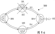
Fig. 1 c represents to have the communications network system of node failure.
Fig. 2 represents detailed node structure.
Fig. 3 represents a detailed first node and a tail node.
Fig. 4 represents the node structure of a modification.
Fig. 5 a represents a bus communication network system.
Fig. 5 b represents the bus communication network system that link cuts off.
Fig. 6 represents that the operating state node becomes the flow chart of the method for first node.
Fig. 7 represents that the node of guard mode becomes the flow chart of the method for normal node.
Fig. 8 represents that the node of operating state becomes the flow chart of the method for tail node.
Fig. 9 represents that the node of guard mode becomes the flow chart of the method for normal node.
Embodiment describes
Fig. 1 a represents to implement the schematic diagram of a communication loop network 100 of the present invention.Network 100 has the node 102-108 with transmission link such as optical fiber link 110 interconnected quantity N.N representative at least 3, expression network 100 is made up of three nodes at least.Transmission link 110 comprises: first transmission link or building ring 112 and second transmission link or guard ring 114.Building ring 112 is a clockwise direction a transmission direction business transferring in the drawings.Guard ring 114 is a counter-clockwise direction in opposite transmission direction business transferring in the drawings.Business for example can be energy or a wavelength channel electric, light.If the use wavelength channel then has the transmitting channel of M light, M can less than, be equal to or greater than the N node.Fig. 1 a also is illustrated in the communication network 100 in its normal operating conditions, and M bar optical channel is independently launched (ASE) transmission with image intensifer in one direction by building ring 112 here.In guard ring 114, just ASE power in the opposite direction propagates into building ring 112.This communication network 110 can be a wavelength division multiplexing self-healing ring communication network 100, as among Fig. 1 a.The network of other type for example is wavelength division multiplexing (WDM) network, and is not shown here, also can be used as this communications network system.Each node 102-108 in the communication network 100 can comprise light adding/taking-up multiplexer 118; OADM, it can add/take out the business of wavelength channel or this node special use, i.e. local service; With other business of bypass.The channel of some wavelength can be exclusively used in a node, the other wavelength channel will by with the next node that enters in the building ring 112.
Fig. 1 b represents to have the communication network 100 of link failure as the cut-out of the optical cable between node 102 and node 104.Itself take safeguard measure and do not relate to network management system 116 in the inside of node 102 and 104, when event of failure, just notify this network management system 116.Safeguard measure by this node by usefulness electronic equipment and the combined realization of on/off signal in the node of work/guard ring 112,114 itself.When link failure such as optical cable occurring and cut off, this node 102 oneself is detected by it and it automatically transfers to guard ring 114 with the business on the building ring 112 itself.Leaving all business of node 102 then gets back to guard ring 114 and tail node occurs.When link failure such as optical cable occurring and cut off, node 104 detects also that it is own and automatically business is transferred to building ring 112 from guard ring 114 by it itself.Leaving all business of node 104 then gets back to building ring 112 and a first node occurs.Node 106 and 108 plays a part transit node, this means usually only also on guard ring 114, to send at a wavelength channel that sends on the building ring 112, but just by node 106 and 108 and do not add/take out any wavelength channel.When the wavelength channel that sends turned back to this node on the building ring 112, then adding/taking-up channel was as working each node normal condition.
In fact the link failure that has at least two classes such as optical cable to cut off; One class is when the fault of cutting off as optical cable occurring, only occurs in building ring 112, and another kind of is when the fault of cutting off as optical cable occurring, only occurs in guard ring 114.When on building ring 112, breaking down, after this fault at the first node 104 of traffic direction in clockwise automatically by node headed by its own its operator scheme of change.Automatically oneself changing its operator scheme by it at the final node 102 in traffic direction is clockwise before the fault is tail node.Under second kind of situation; when in guard ring 114, occurring as during the fault of optical cable cut-out; it is tail node that the final node 102 that is in traffic direction before fault automatically oneself changes its operator scheme by it, and is in first node 104 in the traffic direction automatically by node headed by its own its operator scheme of change after fault.
Therefore Fig. 1 c represents to have the communication network 100 of node failure, as among Fig. 1 b, with reconfiguring of same type occurring, promptly changes operator scheme, sets up a first node, i.e. node 104 and a tail node, and promptly node 108.Between first node 104 and tail node 108, transit node 106 is arranged also in this example.
Fig. 2 represents the block diagram according to light adding/taking-up multiplexer node 200 of the present invention, and this node can be any node 102-108 among Fig. 1.Node 200 has a building ring input 202, and it receives the first smooth transmission device, for example first imports optical link 210, and it can be an optical fiber.First light input 216 of light conversion device is received in building ring input 202, and light conversion device is first optical switch 214 for example, and it can be converted and be operated in straight-through (bar) or crossing condition.The second smooth transmission device for example can be the guard ring input 208 that the second input optical link 2020 of optical fiber is received node 200.Second light input 218 of first optical switch 214 is received in this guard ring input 208.First optical switch 214 is received first light input 216 in pass-through state, and first light input 228 of optical channel selector switch or wavelength-selective switches 226 is received in first light output 230 of optical switch 214, and optical channel selector switch 226 also is operated in straight-through or crossing condition.First light output 244 at the described channel selection switch 226 of pass-through state is received in first light input 228 of channel selection switch 236.This first light is exported 244 light and is connected in the line terminal 274 input 242, and line terminal 274 is relevant with this node.Output 246 light of line terminal 274 are connected to second input 248 of channel selection switch 226.Second light output, 236, the second light that this second input 248 is received described channel selection switch 226 in pass-through state are exported 236 light and are connected to first input 234 of light conversion device as second optical switch 232.Second optical switch 232 can be operated in straight-through or crossing condition.Second input 238 of second optical switch 232 is received second output 240, the second of first optical switch 214 and is exported 240 second inputs 218 of receiving pass-through state.
Second optical switch 232 that is in pass-through state is received first input 234, and image intensifer 260 is received in first output 250 of switch 232, and image intensifer 260 is received the first smooth cut-off switch 264 again.This switch 264 is received the building ring output 206 in the node 200.The 3rd smooth transmission device 270 is received in building ring output 206.Receive second output 252 of second optical switch 232 of second input 238 in pass-through state and receive second image intensifer 262, amplifier 262 is received the second smooth cut-off switch 266 again.The second smooth cut-off switch 266 is received the guard ring output 204 in the node 200, and the 4th smooth transmission device 272 is received in guard ring output 204.
The first input link monitoring arrangement is connected to first input 216 of first optical switch 214 as first fault monitor, 222 light.The second input link monitoring arrangement couples light to second input 218 of first optical switch 214 as second fault monitor 224.The first power detection monitor 254 couples light to first output 250 of second optical switch 232, and the second power detection monitor 256 couples light to second output 252 of second optical switch 232.Fault monitor 222 and 224, amplifier 260 and 262 and power detection monitor 254 and 256 be connected electrically to control device or local control unit 258.258 control first and second optical switch 214 and 232, wavelength-selective switches 226 and first and second cut- off switch 264 and 266, unit.Local control unit 258 is received network administration apparatus, promptly so-called network management system 116, and it is positioned at outside the node 200.This network management system is also correspondingly received other node.
The first smooth transmission device and the 3rd smooth transmission device 270 of receiving building ring output 206 of receiving the building ring input 202 of light adding/taking-up multiplexer node 200 constitute the part of building rings 112; referring to Fig. 1; in Fig. 2; the second smooth transmission device 222 and the 4th smooth transmission device 272 of receiving guard ring output 204 of receiving the guard ring input 208 of light adding/taking-up multiplexer node 200 constitute the part of guard rings 114, referring to Fig. 1 b.
(Fig. 1 a) when light adding/taking-up multiplexer node 200 is in normal operating conditions, M wavelength channel number enters node 200 from building ring input 202, and in that their arrive wavelength-selective switches 226 after being in first optical switch 214 in the pass-through state.Wavelength-selective switches 226 is carried out wavelength channel adding/taking-up, the i.e. wavelength channel of local service and bypass node 200.Wavelength-selective switches 226 is selected and is taken out the wavelength channel that is exclusively used in node 200 and pass to line terminal 274 on its input 242 (RX).Line terminal 274 comprises that wave device is received the optical receiver of input 242 and received the transmitter of output 246 after filtration.Line terminal 274 also comprises the device that is used for demodulation modulated light (not shown) and is used for conversion that this is modulated to the device of signal of telecommunication (not shown), also is useful on through the device of these signals of telecommunication of electricity output transmission to dedicated receiver.Also input receives the signal of telecommunication that comprises information through electricity in line terminal 274, and these signals send to receiver by network 100.The signal of telecommunication is transformed, so that utilize selected wavelength to carry out light modulation, it is sent to this transmitter so that be added to network 100.Network management system 116 is communicated by letter with local control unit 258 through standard interface.After this local control unit 258 control wavelength-selective switches 266 obtain desired selection.Wavelength-selective switches 226 will be added in output 246 (TX) from the new local service of line terminal 274.Which wavelength channel is network management system 116 can order to be added to building ring 112.Wavelength-selective switches 226 bypass and equilibrium are not all wavelengths channels that is exclusively used in this node.Wavelength channel that is added and bypass are from second optical switch 232 by being in pass-through state of the wavelength channel of wavelength-selective switches 226, be exaggerated and pass through the OADM node that light cut-off switch 264 input service rings output 206 arrives back by image intensifer 260 (for example fiber amplifier EDFA of er-doped).As shown in Figure 2, guard ring output 204 is received in guard ring input 208, and this is to utilize two optical switches 214 and 232 that all are in pass-through state to obtain.This any luminous power that does not allow to import this Node Protection ring input 208 is amplified by second image intensifer 262 simply, and is sent to guard ring output 204.
The wavelength channel of input light adding/taking-up multiplexer node 200 has different power levels and passes through network 100 for fear of unbalanced channel power, needs the power equalization of wavelength channel in each node 200.In order to realize such function, take out the Output optical power of some by power detection monitor 254, power detection monitor 254 is measured this optical level.Optical level sends to local control unit 258, and the latter calculates the pad value of each wavelength channel, so that obtain equilibrium.Local control unit 258 sends this pad value to wavelength-selective switches 226, and the latter selectively is added to them corresponding channel.
The present invention relates to see Fig. 1 b at the network disaster recovery that for example when link has fault, utilizes node between two nodes between the node 102 and 104.
First event of failure may be when building ring 112 and guard ring 114 have fault.110 of communication networks will be reconfigured from first node mode and the tail node pattern of changing into Fig. 1 b respectively by them by node 102 and 104.
For the fault of finding first transmission link or building ring 112 as disconnecting, light addings/the taking-ups multiplexer node 200 among Fig. 2 is equipped first fault monitor 222, its branch imports 202 sub-fraction input optical power from building ring.This may be wavelength channel and/or ASE power.Local control unit 258 obtains information from first fault monitor 222, and if any luminous power is arranged, then first fault monitor 222 rests in its operating state.If if building ring 112 existing faults and change are professional to guard mode.Then on first fault monitor 222, there is not luminous power.ASE power still exists in the guard ring 114.Any detection of the loss of traffic of being undertaken by first fault monitor 212 begins to carry out reconfiguring of node 200 by local control unit 258.First fault monitor 222 or local control unit 258 enter guard mode.After first fault monitor 222 was known fault detect, local control unit 258 was transformed into crossing condition with first optical switch 214 from pass-through state.First optical switch, 214 meanings in the crossing condition are: first light output 230 of second light input, 218 and first optical switch 214 of first optical switch 214 is connected to each other.This means that ASE power and/or business on guard ring 114 are transferred to building ring 112.Local control unit 258 also will be opened second cut-off switch 266, therefore both not have business and also do not have ASE power and can be added to guard ring and export 204 after conversion.At this moment node 200 has entered the first node mode shown in Fig. 1 b.Local control unit 258 is communicated by letter with network management system 116 and notified: node 104 has become a first node.
First node returns to operating state from guard mode process is by network management system 116, and network management system 116 is communicated by letter with local control unit 258.In order to begin recovery process from first node, 258 closures of local control unit, second cut-off switch 266, and connect second image intensifer 262, if this link fault-free such as optical fiber do not damage, then luminous power can arrive previous node (tail node) in business changes its course.Local control unit 258 checks whether first fault monitor 222 detects any luminous power from building ring input 202.This power can be wavelength channel and/or ASE power.If first fault monitor 222 detects luminous power, then this node enters operating state.First fault monitor 222 or local control unit 258 enter operating state.Local control unit 258 is transformed into pass-through state with first optical switch 214 from crossing condition, and therefore can import 202 from building ring receives business.At this moment should business export 206 by building ring input 202 to building ring, this business that is illustrated in building ring 112 is returned, and ASE power exports 208 from guard ring input 204 to guard ring.Local control unit 258 informing network management systems 116 these nodes 104 are got back to operating state.If first fault monitor 222 does not detect any luminous power, it will rest in its guard mode.After certain hour, 500ms for example, local control unit 258 turn-offs second image intensifer 262, opens second cut-off switch 266 and cancels this recovery process.Local control unit 258 informing network management systems 116, the recovery of node 104 is cancelled.
In order to find, damage as second transmission link or guard ring 112, light adding/taking-up multiplexer node 200 equipments second fault monitor 224 among Fig. 2, it is from guard ring input 208 shunting sub-fraction input optical powers.This can be ASE power and/or wavelength channel.Local control unit 258 obtains information from second fault monitor 224, and if without any luminous power, second fault monitor 224 rests in its operating state.If if guard ring 114 existing faults and business change to guard mode; on second fault monitor 224, there is not luminous power; ASE power can still exist in building ring 112, and any detection of being carried out ASE power or loss of traffic by second fault monitor 224 begins to carry out reconfiguring of node 200 by local control unit 258.Second fault monitor 224 or local control unit 258 enter guard mode.After second fault monitor 224 was known fault detect, local control unit 258 was transformed into crossing condition with second optical switch 232 from pass-through state.Second optical switch 232 is represented in crossing condition: second light output 252 of first light input, 234 and second optical switch 232 of second optical switch 232 is connected to each other.This means: the business on building ring 112 is transferred to guard ring 114.Local control unit 258 also will be opened first cut-off switch 264, therefore both not have business also not have ASE power can be added to building ring output 202 after conversion.At this moment node 200 has entered the tail node pattern, as among Fig. 1 b.Local control unit 258 is communicated by letter with network management system and informing network management system 116, and node 102 has become tail node.
Tail node returns to the process of operating state by network management system 116 from guard mode; system 116 communicates by letter with local control unit 258 for from tail node recovery process; local control unit 258 closures, first cut-off switch 264 and connect first image intensifer 260; if this link fault-free; not damaged as optical fiber, then luminous power can arrive back one node (first node) after traffic diversion.Local control unit 258 checks whether second fault monitor 224 detects any luminous power from guard ring input 208.This power can be wavelength channel and/or ASE power.If second fault monitor 224 detects luminous power, then node enters operating state.Second fault monitor 224 or local control unit 258 enter operating state.Local control unit 258 is transformed into illegal state with second optical switch 232 from crossing condition, and the business that makes can turn back to building ring output 206, at this moment professional by building ring input 202 to building ring output 206, this business that is illustrated on the building ring 112 is returned.ASE power exports 208 from guard ring input 204 to guard ring.Local control unit 258 informing network management systems 116: node 102 has turned back to operating state.If second fault monitor 224 does not detect any luminous power, it will rest in its guard mode.After certain hour, 500ms for example, local control unit 258 turn-offs first image intensifer 260, opens first cut-off switch 264 and cancels recovery process.Local control unit 258 informing network management systems 116: the recovery of node 102 is cancelled.
Although link has fault between node 102 and the node 104, there is not loss of traffic yet.Professional will between the first node 104 of communication network 100 and tail node 102, the transmission, they still detect light energy, promptly at signal on the two of their fault monitor 222,224 of Fig. 2, keep their normal configurations.This allows network 100 to keep the normal function of building ring 112.Tail node 108 is transferred to guard ring output 204 from building ring input 202 soon with all wavelength channels.First node 104 is transferred to building ring output 206 from guard ring input 208 soon with all wavelengths channel.Arrive first node by tail node to guard ring 114 traffic diversions, first node turns back to building ring 112 and forms a loop.Have a node between first node and tail node at least, this (a bit) node is in this case as transit node 106,108 work.Transit node 106,108 just is being the node of head or tail node.They can be on building ring 112 and/or retaining ring 114 adding/taking-up wavelength channel, bypass wavelength channel.
In Fig. 3 a, second event of failure may be when only on building ring 112 fault being arranged.If building ring 112 has fault, as damaging, first fault monitor, 222 detection signals are lost and start node 104 reconfigure headed by node, see first event of failure, it opens second cut-off switch 266.These feasible second fault monitor, 224 dropouts of node 102 in front, node 102 start nodes 102 in front are reconfigured for tail node, see first event of failure, and it opens first cut-off switch 264.
In Fig. 3 b, the 3rd event of failure may be when only on guard ring 114 fault being arranged.If guard ring 11 4 has fault, as disconnecting, then individual node recovery action is identical, but compares with second event of failure, is to carry out with opposite sequence order.This means it at first is that the first then node of tail node occurs, obtain node state and the communication path identical with first event of failure.
The invention still further relates to when 102 of a node such as Fig. 1 c has fault, have with first event of failure in the fault recovery of identical process.Difference is that different nodes will become first node and tail node.In this event of failure, node 104 will become first node 104, see first event of failure, and node 108 will become tail node 108, see first event of failure.Malfunctioning node 102 is kept apart with other node among Fig. 1 c.
The process of any event of failure of above-mentioned recovery with recover first node from guard mode and recover the identical mode of tail node from guard mode and carry out.
Fig. 4 represents to can be used as the block diagram of the substitute node 400 of first node and/or tail node.Substitute node 400 can be according to any the node 102-108 among Fig. 1 of the present invention.Substitute node 400 has building ring input 202, receives first smooth transmission device 210, for example optical fiber.First light input 404 of optical switch or optical switch device 402 is received in building ring input 202, and optical switch device 402 can be converted and be operated in for example pass-through state, first crossing condition and/or second crossing condition.It also may be the guard ring input 208 that the second smooth transmission device 220 of optical fiber is received node 400.Second light input 406 of optical switch 402 is received in this guard ring input 208.Be in first light output 408 that pass-through state is coupled to the optical switch 402 of first light input 404 and receive the first smooth cut-off switch 264.The 3rd smooth transmission device 270 is received building ring output 206, and the first smooth cut-off switch 264 is received in building ring output 206.The second smooth cut-off switch 266 is received in second light output 410 of being coupled to the optical switch 402 of second light input 406 in pass-through state.The 4th smooth transmission device 272 is received guard ring output 204, and the latter receives the second smooth cut-off switch 266.First fault monitor, 222 light are connected to first input 404 of optical switch 402.Second fault monitor 224 couples light to second input 406 of optical switch 402.Fault monitor 222 and 224 and optical switch 402 be electrically connected to control device or local control unit 258, the latter controls first and second cut-off switch 264 and 266.Local control unit 258 is received network administration apparatus or network management system 116, and the latter is outside this node.Network management system 116 is correspondingly also received other node.
When substitute node 400 was operating state, as shown in Figure 1a, the wavelength channel of quantity M entered node 400 from building ring input 202, and their optical switches 402 by being in pass-through state.Local control unit 258 control optical switches 402, and the process standard interface is communicated by letter with network management system.As shown in Figure 4, the first smooth transmission device 210 and building ring input 202 are received the 3rd smooth transmission device 270 through the optical switch 402, first cut-off switch 264, the building ring output 206 that are in pass-through state, and the part of the building ring 11 2 of pie graph 1a.Also as shown in Figure 4; the second smooth transmission device 220 and the guard ring input 208 of receiving the second smooth transmission device 220 are linked guard ring output 204, the part of the guard ring 114 shown in the pie graph 1a through the optical switch 402, second cut-off switch 226 that are in pass-through state.
In order to find that in first transmission link or building ring fault is as disconnecting node 400 equipments first fault monitor 222 among Fig. 4.Monitor 222 is a spot of luminous power of shunting from building ring input 202.This can be wavelength channel and/or ASE power.Local control unit 258 obtains information from first fault monitor 222, and if any luminous power is arranged, then fault monitor 222 rests on its operating state.If building ring 112 existing faults, then fault monitor 222 is transformed into guard mode.ASE power still is present in the guard ring 114.Any detection of carrying out loss of traffic by first fault monitor 222 by local control unit 258 begin to carry out, the reconfiguring of node 400.First fault monitor 222 or local control unit 258 change guard mode over to.After fault detect, local control unit 258 is transformed into first crossing condition with optical switch 402.First crossing condition is meant that second input 406 of optical switch 402 and first output 408 of optical switch 402 are connected to each other.This means: ASE power and/or business on the guard ring 114 fold on the building ring 112.Local control unit 258 also will be opened second cut-off switch 266, therefore can enter guard ring output 204 without any business or ASE power after conversion.At this moment node 400 has entered first node.At this moment local control unit 258 is communicated by letter with network management system 116 and is notified node 104 to become first contact.
The recovery process of first node is to carry out with aforesaid same way as.Difference is that optical switch 402 will be got back to pass-through state, and first light output 408 of optical switch 402 is coupled in first light input 404 of this expression optical switch 402.
For the fault of finding second transmission link or guard ring as disconnecting node 400 equipments second fault monitor 224 among Fig. 4.Monitor 224 is from a spot of luminous power of guard ring input 208 shuntings.This may be ASE power and/or wavelength channel.Local control unit 258 obtains information from second fault monitor 224, and if any luminous power is arranged, then fault monitor 224 rests on its operating state.If guard ring 114 existing faults, then fault monitor 224 is transformed into guard mode.ASE power still can appear in the building ring 112.Any detection of the loss of traffic that second fault monitor 224 carries out begins to carry out reconfiguring of node 400 by local control unit 258.Second fault monitor 224 or local control unit 258 change guard mode over to.After fault detect, local control unit 258 convert light switches 402 to second crossing condition.Second crossing condition is meant that first input 404 of optical switch 402 and second output 410 of optical switch 402 are connected to each other.The business on the building ring 112 that this means folds into guard ring 114.Local control unit 258 is also opened first cut-off switch 264, and therefore business or ASE power all can not enter building ring output 202 after conversion.Node 400 will become tail node.Local control unit 258 is communicated by letter and informing network management system 116 with network management system 116: node 102 has become tail node.
The recovery process of this head node is carried out with aforesaid same way as.Unique difference is that optical switch 402 is got back to pass-through state, this means that second light of optical switch 402 is imported 406 second light outputs 410 of being coupled to optical switch 402.
Fig. 5 a represents that an alternative communication network promptly realizes the schematic diagram of bus communication network 500 of the present invention.Bus communication network 500 has the node 502-508 with bus transfer link such as bus optical link 510 interconnected quantity N.First node or start node 502 are at one end arranged, and its possibility designate similar node 200 or 400 has N or end node 508 in the opposite end, and its may designate similar node 200 or 400.Bus transfer link 510 comprises the first bus transfer link or active link 512 and the second bus transfer link or protection link 514.On start node 502, active link 512 with the protection link 514 be connected and node 502 as tail node, see first event of failure.On end node 508, the protection link 514 be connected with active link 512 with node 508 as first node, see first event of failure.Bus communication net 500 is made of together first node 502, end node 508, active link 512 and protection link 514.Bus communication net 500 passes through active link 512 and in the opposite direction sends wavelength channels by protection link 514 in a direction.Fig. 5 a also is illustrated in the bus communication net 500 in the operating state, this means that the N wavelength channel is sent to protection link 514 in a direction by active link 512 with ASE power.This bus communication net 500 also may be a wavelength division multiplexing self-healing bus communication net.Unshowned here other type bus communication network can be used as this bus communication net.Each node in the bus communication net 500 can comprise a light adding/taking-up multiplexer, and this multiplexer can add/take out channel and other channel of bypass that the business that is exclusively used in this node is this city business.Can be used as first node, tail node or transit node such as other node among Fig. 4.500 work of bus communication net are foregoing.
Fig. 5 b represents that line fault is as two local A that cable cutting may occur and the example of B.Cable cutting can be at the bus communication net Anywhere.Each node after cable cutting will be as first node and each node before cable cutting as tail node, described as the front in conjunction with Fig. 2 and Fig. 4.
Fig. 6 represents that a node becomes the method for the first node 104 of Fig. 1 b that narrates previously in this part, and key step is as follows:
-operating state, square frame 600;
-fault monitor 222 shunting luminous powers, square frame 602;
The information of-shunting is to control unit 258, square frame 604;
-in fault monitor 222, is there there any luminous power? square frame 606;
If the problem at square frame 606 is not, then take following key step:
-node is to guard mode, square frame 608;
-optical switch 214 is to crossing condition, square frame 610;
-open cut-off switch 266, square frame 612;
-notifying management system 116; Node is first node, square frame 614;
-guard mode (first node), square frame 616.
If in the problem of square frame 606 for being then to take following key step:
-operating state, square frame 620;
Fig. 7 is illustrated in the method how node in the guard mode becomes normal node, and this is previous narration in this part, and key step is as follows:
-guard mode (first node), square frame 700;
-first node recovers beginning, square frame 702;
-closed cut-off switch 266, square frame 704;
-connection amplifier 262, square frame 706;
-in fault monitor 222, is there there any luminous power? square frame 708;
If in the problem of square frame 708 for being then to take following key step:
-node is to operating state, square frame 710;
-optical switch 214 is to pass-through state, square frame 712;
-notifying management system 116 nodes are normal, square frame 714;
-operating state, square frame 716;
If the problem at square frame 708 is not, then take following key step:
-shutoff amplifier 262, square frame 720;
-open cut-off switch 266, square frame 722;
-notifying management system 116 those nodes are first nodes, square frame 724;
-guard mode (first node), square frame 726.
Fig. 8 represents that node becomes the method for the tail node of Fig. 1 b, and this is previous narration in this part, and key step is as follows:
-operating state, square frame 800;
-fault monitor 224 shunting luminous powers, square frame 802;
The information of-shunting is to control unit 258, square frame 804;
-in fault monitor 224, is there there any luminous power? square frame 806;
If the problem at square frame 806 is not, then take following key step:
-node is to guard mode, square frame 808;
-optical switch 232 is to crossing condition, square frame 810;
-open cut-off switch 264, square frame 812;
-notifying management system 116: that node is a tail node, square frame 814;
-guard mode (tail node), square frame 816.
If in the problem of square frame 806 for being then to take following key step:
-operating state, square frame 820.
Fig. 9 represents how the node in the guard mode becomes the method for normal node, and this is previous narration in this part.Key step is as follows:
-guard mode (tail node), square frame 900;
-tail node is recovered beginning, square frame 902;
-closed cut-off switch 264, square frame 904;
-connection amplifier 260, square frame 906;
-in fault monitor 224, is there there any luminous power? square frame 908;
If the problem at square frame 908 is not, then take following key step:
-node is to operating state, square frame 910;
-optical switch 232 is a pass-through state, square frame 912;
-notifying management system 116: that node is normal, square frame 914;
-operating state, square frame 916;
If in the problem of square frame 908 for being then to take following key step:
-shutoff amplifier 260, square frame 920;
-open cut-off switch 264, square frame 922;
-notifying management system 116: that node is a tail node, square frame 924;
-guard mode (tail node), square frame 926.
Advantage is that channel selection switch does not participate in node and reconfigures process.This means: thus it be not subjected to the professional route of influence of any transition and during the node reconfiguration procedure adding/taking-up function be stable.
Above-mentioned invention is with the optical solutions narration, but this dispensable requirement.
Above-mentioned invention can realize with other concrete form under the situation that does not break away from its spirit or essential characteristic.Therefore, say that from every side these embodiment are considered to illustrative and not restrictive; Scope of the present invention by claims not the narration with the front show, implication and the institute in the equivalent scope change and all be comprised in wherein.
Claims (13)
1. a communication node (200,400) receives light energy and upward sends light energy and other node communication at first (270) and the second output optical link (272) by going up at first (210) and the second input optical link (220), and this node comprises:
The first input link monitoring arrangement (222) detects from the light energy of first input optical link (210) input;
The second input link monitoring arrangement (224) detects from the light energy of second input optical link (220) input;
Light conversion device (214,232,402) will be imported light energy and be transferred to first (270) or the second smooth output link (272) from first (210) or the second smooth input link (220);
Control device (258) is received this monitoring arrangement and conversion equipment, and response is controlled normal mode (106), first pattern (104) or Tail Model (108) that this node becomes work one or two detection of importing input light energy on the optical link; With
Recovery device, when this node was in head or Tail Model, it was possible detecting whether this node returns to normal mode.
2. according to the communication node of claim 1, wherein this recovery device comprises the cut-off switch that is suitable for setting up an independent test loop that recovers test, wherein this control device is applicable to that this node of control becomes normal mode from head or Tail Model, thereby this node is applicable to that transmitting light energy from first input link transmits light energy to second output link to first output link with from second input link.
3. according to the communication node of claim 1, wherein this control device is suitable for detecting from first rather than controlling this node during from intake that second input link comes and become tail node at this link monitoring device, thereby this node is applicable to from first input link and transmits light energy to second output link rather than to first output link.
4. according to the communication node of claim 1, wherein detect from second rather than during when this link monitoring device from intake that first input link comes, this control device is applicable to that this node of control becomes first pattern, thereby this node is applicable to that the light energy that sends to come from second input link is to first output link rather than to second output link.
5. according to the communication node of any claim of claim 1 to 4, wherein: first input and output link are connected to other node separately, constitute the part of first transmission link (112,512) of communication loop network; With
Second input and output link are connected to node separately, constitute the part of second transmission link (114,514) of this communication loop network.
6. one kind comprises three nodes (200 at least; 400) communications network system (100; 500); these node utilization carrying wavelength channels are to the transmission link (110 from these nodes; 510) interconnection; transmission link is divided into first transmission link (112; 512) and second transmission link (114; 514); these nodes have building ring input (202) and the building ring output (206) that is used for first transmission link; and have guard ring input (204) and the guard ring output (208) that is used for second transmission link, and first and second transmission links can in the opposite direction send wavelength channel, and each node comprises:
Malfunction monitoring apparatus (222,224) is used for the detection of luminous power, and described device is received building ring input and guard ring input;
Conversion equipment (214,232,402) is transformed into second transmission link with wavelength channel from first transmission link;
Local control unit (258) is connected to malfunction monitoring apparatus but also receives the device of Wavelength-converting channel; With
Whether recovery device when this node is in protected mode, detects this node and returns to mode of operation and may.
7. according to the communications network system of claim 6, wherein this recovery device comprises and is suitable for setting up the cut-off switch that is used to the independent test loop that recovers to test.
8. communication network (100; 500) node (200 in; 400); this node utilization carrying wavelength channel to and from the transmission link (110 of node; 510) be interconnected to other node; this transmission link is divided into first transmission link (112; 512) and second transmission link (114; 514); these nodes have building ring input (202) and the building ring output (206) that is used for first transmission link; and have guard ring input (204) and the guard ring output (208) that is used for second transmission link, and first and second transmission links can in the opposite direction send wavelength channel, and each node comprises:
Malfunction monitoring apparatus (222,224) is used for the detection of light energy, and described device is received this building ring input and the input of this guard ring;
Wavelength channel is transformed into the device (214,232) of second transmission link from first transmission link;
Local control unit (258) is connected to malfunction monitoring apparatus but also receives the device of Wavelength-converting channel; With
Whether recovery device when this node is in protected mode, detects this node and returns to mode of operation and may.
9. node according to Claim 8, wherein this recovery device comprises and is suitable for setting up the cut-off switch that is used to the independent test loop that recovers to test.
10. be used for through a kind of optical node (400) that the light transmission device receives and the transmission wavelength channel is communicated by letter with other optical node, this node comprises:
An optical switch (402), comprise first (404) and second (406) input and first (408) and second (410) output, described switch can be changed between pass-through state and crossing condition, in pass-through state first input (404) is connected with output (408) and wherein second input (406) be connected with output (410), and in crossing condition, first import (404) and second and export (410) and be connected with second and import (406) and first and export (408) and be connected;
First fault monitor (222) that is used for light energy detection, described fault monitor couple light to first input (404) of this optical switch (402);
Second fault monitor (224) that is used for light energy detection, described fault monitor couple light to second input (406) of this optical switch (402);
The first smooth cut-off switch (264), first light output (408) of receiving this optical switch (402);
The second smooth cut-off switch (266), second light output (410) of receiving this optical switch (402);
Building ring input (202), first light input (404) of receiving the first smooth transmission device (210) and this optical switch (402);
Guard ring input (208), second light input (406) of receiving the second smooth transmission device (220) and this optical switch (402);
The first smooth cut-off switch (264) and the 3rd smooth transmission device (270) are received in building ring output (206);
The second smooth cut-off switch (266) and the 4th smooth transmission device (272) are received in guard ring output (204).
11. be used for through a kind of light adding/taking-up multiplexer node (200) that the light transmission device receives and the transmission wavelength channel is communicated by letter with other optical node, this node comprises:
First optical switch (214), comprise first input (216) and second input (218), with first output (230) and second output (240), described switch can be changed between pass-through state and crossing condition, first input (216) is connected with output (230) and second input (218) is connected with output (240) in pass-through state, and first imports (216) and second and export (240) and be connected with second and import (218) and first and export (240) and be connected in crossing condition;
Second optical switch (232), comprise first input (234) and second input (238), with first output (250) and second output (252), second output (240) of first optical switch (214) is received in described second input (238), described switch can be changed between pass-through state and crossing condition, first input (234) is connected with output (250) and second input (238) is connected with output (252) in pass-through state, and first imports (234) and second and export (252) and be connected with second and import (238) and first and export (250) and be connected in crossing condition;
Wavelength-selective switches (226), comprise first input (228) and second input (248), with first output (244) and second output (236), first output (230) of first optical switch (214) is received in described first input (228), first input (234) of second optical switch (232) is received in described second output (236), described channel selection switch can be changed between pass-through state and crossing condition, first input (228) is connected with output (244) and second input (248) is connected with exporting (236) in pass-through state, and first imports (228) and second and export (236) and be connected in crossing condition;
A line terminal (274) comprises and receives the output (246) that first of this channel selection switch is exported an input (242) of (244) and comprised second input (248) of receiving this channel selection switch;
First image intensifer (260), first output (250) of receiving second optical switch (232);
Second image intensifer (262), second output (252) of receiving second optical switch (232);
The first smooth cut-off switch (264) is received first image intensifer (260);
The second smooth cut-off switch (266) is received second image intensifer (262);
The first smooth cut-off switch and the first smooth transmission device (210) are received in building ring input (202);
Guard ring input (208) is received first of first optical switch (214) and is imported (216) and the second smooth transmission device (220);
The first smooth cut-off switch (264) and the 3rd smooth transmission device (270) are received in building ring output (206);
The second smooth cut-off switch (266) and the 4th smooth transmission device (272) are received in guard ring output (204);
First fault monitor (222) is used for the detection of light energy, and described device light is connected to first input (216) of first optical switch (214);
Second fault monitor (224) is used for the detection of light energy, and described device light is connected to second input (218) of first optical switch (214); With
Local control unit (258) is connected to network management system (116), described local control unit (258) control: first and second optical switches (214,232), wavelength-selective switches (226) and first and second light cut-off switch (264,266).
12. one kind is used for recovering at least three nodes (200; 400) network system (100; 500) method; node utilizes transmission link (110; 510) interconnection; each node comprises receives first transmission link (112; 512) building ring input (202) and building ring output (206); and comprise and receive second transmission link (114; 514) guard ring input (204) and guard ring output (208); first and second transmission links can in the opposite direction send signal, and this method may further comprise the steps:
All nodes in this system are in mode of operation, and wherein signal sends on first transmission link;
When utilizing the decay detection failure of input optical power, some nodes enter protected mode and change the state of optical switch device (214,232,402), therefore use two transmission links to set up transmit ring, and described transmit ring does not transmit this fault;
Repair a breakdown;
Estimate that by setting up the test loop transmission fault that may repair begins to recover test, described test loop is what to separate with this transmit ring;
When detecting in this test loop no luminous power, node rests on protected mode;
During luminous power in detecting this test loop, node becomes mode of operation and changes the state of light conversion device, so signal sends on first transmission link once more;
Notifying management system has the situation of artis.
13. according to the method for claim 12, wherein
This test loop is set up by closed cut-off switch (264,266), otherwise cut-off switch is opened during protected mode.
Applications Claiming Priority (6)
| Application Number | Priority Date | Filing Date | Title |
|---|---|---|---|
| SE9502310-7 | 1995-06-26 | ||
| SE9502310A SE506713C2 (en) | 1995-06-26 | 1995-06-26 | Self healing communication node network with main and protection rings |
| SE95023107 | 1995-06-26 | ||
| SE9503573-9 | 1995-10-12 | ||
| SE9503573A SE9503573D0 (en) | 1995-10-12 | 1995-10-12 | Self-healing network |
| SE95035739 | 1995-10-12 |
Publications (2)
| Publication Number | Publication Date |
|---|---|
| CN1189269A CN1189269A (en) | 1998-07-29 |
| CN1094007C true CN1094007C (en) | 2002-11-06 |
Family
ID=26662328
Family Applications (1)
| Application Number | Title | Priority Date | Filing Date |
|---|---|---|---|
| CN96195023A Expired - Lifetime CN1094007C (en) | 1995-06-26 | 1996-06-18 | self-healing network |
Country Status (9)
| Country | Link |
|---|---|
| US (1) | US6088141A (en) |
| EP (1) | EP0878079B1 (en) |
| JP (1) | JPH11508427A (en) |
| CN (1) | CN1094007C (en) |
| AU (1) | AU6322696A (en) |
| BR (1) | BR9608792A (en) |
| DE (1) | DE69634611T2 (en) |
| ES (1) | ES2239333T3 (en) |
| WO (1) | WO1997001907A1 (en) |
Cited By (2)
| Publication number | Priority date | Publication date | Assignee | Title |
|---|---|---|---|---|
| CN100430495C (en) * | 2002-12-05 | 2008-11-05 | Sms迪马格股份公司 | Method for process control or process regulation of a unit for moulding, cooling and/or thermal treatment of metal |
| CN102710326A (en) * | 2012-06-04 | 2012-10-03 | 上海大学 | Wavelength division multiplexing passive optical network system with remote node protecting function and realization method thereof |
Families Citing this family (88)
| Publication number | Priority date | Publication date | Assignee | Title |
|---|---|---|---|---|
| TW353838B (en) | 1996-11-12 | 1999-03-01 | Toshiba Corp | Ring network system and control method of its communication path |
| JPH10247878A (en) * | 1997-03-04 | 1998-09-14 | Kokusai Denshin Denwa Co Ltd <Kdd> | Optical transmission system, optical distributor and optical signal processing unit |
| WO1999000942A2 (en) * | 1997-06-27 | 1999-01-07 | Tellabs Denmark A/S | A method of transmitting data in a ring-shaped teletransmission network, such a network and a network element therefor |
| GB2327020A (en) * | 1997-06-30 | 1999-01-06 | Ericsson Telefon Ab L M | A self-healing meshed network |
| NO307639B1 (en) * | 1997-10-24 | 2000-05-02 | Ericsson Telefon Ab L M | Procedure for establishing alternative routes in a telecommunications network |
| US6057948A (en) * | 1997-11-03 | 2000-05-02 | Ciena Corporation | Protection switch optical communications system |
| US6266168B1 (en) | 1997-12-19 | 2001-07-24 | Lucent Technologies Inc. | Optical protection switch employing an interference filter |
| US6233072B1 (en) * | 1997-12-31 | 2001-05-15 | Mci Communications Corporation | Method and system for restoring coincident line and facility failures |
| US6052210A (en) * | 1998-01-14 | 2000-04-18 | Mci Communications Corporation | System and method for increasing the robustness of an optical ring network |
| JPH11313095A (en) * | 1998-04-28 | 1999-11-09 | Nec Corp | Ring network system, protection method and protection processing program recording medium |
| GB2338370B (en) | 1998-06-09 | 2000-07-19 | Plessey Telecomm | Telecommunications system |
| SE520876C2 (en) * | 1998-06-10 | 2003-09-09 | Ericsson Telefon Ab L M | ADD / Drpo node for an optical WDM network that has traffic only between neighboring nodes |
| SE521135C2 (en) * | 1998-06-17 | 2003-10-07 | Ericsson Telefon Ab L M | A communication network and a fault management method in such a network |
| US6262820B1 (en) * | 1998-07-15 | 2001-07-17 | Lucent Technologies Inc. | Optical transmission system including optical restoration |
| DE19832039A1 (en) * | 1998-07-16 | 2000-01-20 | Alcatel Sa | Node of a point-to-multipoint network |
| US6466341B1 (en) * | 1998-08-03 | 2002-10-15 | Agere Systems Guardian Corp. | Add/drop filter for a multi-wavelength lightwave system |
| JP3553385B2 (en) * | 1998-08-31 | 2004-08-11 | 三菱電機株式会社 | Optical switching device |
| DE69942014D1 (en) | 1998-12-08 | 2010-03-25 | Nippon Telegraph & Telephone | Optical communication network |
| DE19906195B4 (en) * | 1999-02-15 | 2011-02-24 | Tenovis Gmbh & Co. Kg | Duplicated transmission network and operating method for it |
| JP2000312189A (en) * | 1999-04-28 | 2000-11-07 | Nec Corp | Optical communications equipment |
| US6466540B1 (en) * | 1999-05-05 | 2002-10-15 | International Business Machines Corporation | Self-healing coupler for a serial raid device |
| US6355886B1 (en) * | 1999-05-21 | 2002-03-12 | Tycom (Us) Inc. | Undersea trunk-and-branch logical ring networks |
| US7046929B1 (en) * | 1999-08-24 | 2006-05-16 | Ciena Corporation | Fault detection and isolation in an optical network |
| EP1083691B1 (en) * | 1999-09-07 | 2008-07-02 | Lucent Technologies Inc. | Enhanced multiframe processing for tandem connection trails with transmission protection schemes |
| US7167443B1 (en) * | 1999-09-10 | 2007-01-23 | Alcatel | System and method for packet level restoration of IP traffic using overhead signaling in a fiber optic ring network |
| DE19945840A1 (en) * | 1999-09-24 | 2001-04-19 | Audi Ag | Optical bus system operating method switches from unidirection transmission of information to bidirectional transmission of information when error is detected |
| CN1126331C (en) * | 1999-11-04 | 2003-10-29 | 深圳市中兴通讯股份有限公司 | Automatically protected switching method and device in high rate SDH loop |
| JP4215369B2 (en) * | 2000-02-09 | 2009-01-28 | 株式会社日立コミュニケーションテクノロジー | Network transmission apparatus and network transmission system |
| US20010038473A1 (en) * | 2000-03-10 | 2001-11-08 | Ming-Jun Li | Devices and methods for controlling protection switching in an optical channel shared protection ring |
| US7499647B2 (en) * | 2000-05-22 | 2009-03-03 | Opvista Incorporated | Fully protected broadcast and select all optical network |
| US7120359B2 (en) * | 2000-05-22 | 2006-10-10 | Opvista Incorporated | Broadcast and select all optical network |
| AU2001271829A1 (en) * | 2000-07-07 | 2002-01-21 | Sycamore Networks, Inc. | Bi-directional wavelength switched ring optical protection switching wavelength assignment algorithm |
| EP1217789B1 (en) * | 2000-07-17 | 2012-05-30 | Kabushiki Kaisha Toshiba | Self-relief method and re-estabishing method for traffic |
| FR2813730B1 (en) * | 2000-09-01 | 2004-05-28 | France Telecom | METHOD AND DEVICE FOR PROTECTING A CENTRALIZED WDM OPTICAL RING NETWORK TRANSPORTING DATA STREAMS IN CONNECTED MODE |
| US6757493B1 (en) * | 2000-09-08 | 2004-06-29 | Aurora Networks, Inc. | Communication link with non-intrusive expansion capability |
| US6501871B1 (en) * | 2000-09-08 | 2002-12-31 | Aurora Networks, Inc. | Active equipment protection methods and apparatus communicatively decoupling data add/drops |
| US6980510B1 (en) * | 2000-09-12 | 2005-12-27 | International Business Machines Corporation | Host interface adaptive hub storage system |
| US6721502B1 (en) | 2000-09-30 | 2004-04-13 | Lucent Technologies Inc. | Shared optical protection ring architecture |
| JP2002271267A (en) * | 2001-03-07 | 2002-09-20 | Nec Corp | Network node device, and network system using the same, and method of detecting its hindrance location |
| US20020131431A1 (en) * | 2001-03-14 | 2002-09-19 | Wank Richard B. | Method and apparatus for a network element to support a communication link in a communication network |
| US7272307B2 (en) | 2001-05-25 | 2007-09-18 | Tellabs Operations, Inc. | Virtual protection channel for fiber optic ring network |
| DE10127286C2 (en) * | 2001-06-05 | 2003-04-24 | Fujitsu Siemens Computers Gmbh | data ring |
| US6834056B2 (en) * | 2001-06-26 | 2004-12-21 | Occam Networks | Virtual local area network protection switching |
| GB2377140B (en) * | 2001-06-29 | 2005-01-19 | Ibm | Method and apparatus for recovery from faults in a loop network |
| DE10139156B4 (en) * | 2001-08-09 | 2007-02-01 | Siemens Ag | An optical transmission system and method for establishing a spare data connection in a dual-homing transport network |
| FR2829328B1 (en) * | 2001-09-06 | 2004-10-22 | Cit Alcatel | METHOD AND SYSTEM ENSURING PROTECTION OF DATA TRANSMISSION ON AN OPTICAL RING SHAPED BY A SINGLE OPTICAL FIBER |
| US6766482B1 (en) * | 2001-10-31 | 2004-07-20 | Extreme Networks | Ethernet automatic protection switching |
| US6832014B1 (en) * | 2002-02-08 | 2004-12-14 | Marconi Communications, Inc. | Backplane wire and noise eliminator tube |
| US7116905B2 (en) * | 2002-03-27 | 2006-10-03 | Fujitsu Limited | Method and system for control signaling in an open ring optical network |
| US7231148B2 (en) | 2002-03-28 | 2007-06-12 | Fujitsu Limited | Flexible open ring optical network and method |
| US7076163B2 (en) | 2002-03-27 | 2006-07-11 | Fujitsu Limited | Method and system for testing during operation of an open ring optical network |
| CN100433687C (en) * | 2002-07-24 | 2008-11-12 | 中兴通讯股份有限公司 | Method for protecting high-level business in multilevel communication apparatus |
| DE10246007A1 (en) * | 2002-10-02 | 2004-04-22 | Rexroth Indramat Gmbh | communication system |
| CN1319320C (en) * | 2002-10-22 | 2007-05-30 | 华为技术有限公司 | Method for realizing link state feed-through in network |
| CN100431288C (en) * | 2002-11-21 | 2008-11-05 | 中兴通讯股份有限公司 | Method and device for realizing business pretection by adopting tunable light source |
| US20040148437A1 (en) * | 2002-12-12 | 2004-07-29 | Koji Tanonaka | Synchronous network establishing method and apparatus |
| US8909038B2 (en) * | 2003-01-07 | 2014-12-09 | Alcatel Lucent | Method and apparatus providing transient control in optical add-drop nodes |
| US7421197B2 (en) * | 2003-01-21 | 2008-09-02 | Fujitsu Limited | Optical network protection switching architecture |
| FR2856861B1 (en) * | 2003-06-30 | 2007-01-19 | Cit Alcatel | WAVELENGTH MULTIPLEXING RING OPTICAL NETWORK AND SIGNAL TRANSMISSION PROTECTED BY LOCAL STATE SWITCH CONSECUTIVE TO LOCAL INTERRUPTION DETECTION |
| CN1287558C (en) * | 2003-12-29 | 2006-11-29 | 中兴通讯股份有限公司 | Recovering method for optical transmission circular network wrong connection business |
| CN100370780C (en) * | 2004-01-17 | 2008-02-20 | 华为技术有限公司 | Method for automatic adjusting business path for flexible packet ring network |
| WO2006002080A2 (en) * | 2004-06-15 | 2006-01-05 | Opvista Incorporated | Optical communication using duobinary modulation |
| US20060008271A1 (en) * | 2004-07-12 | 2006-01-12 | Loop Telecommunication International, Inc. | Method of failure protection for digital transmission system in ring configuration, and relevant multiplexing device |
| JP4707399B2 (en) * | 2004-07-30 | 2011-06-22 | 富士通株式会社 | Optical add / drop device |
| JP2006050092A (en) * | 2004-08-02 | 2006-02-16 | Pacific Ind Co Ltd | Optical lan system |
| CN100373866C (en) * | 2004-12-24 | 2008-03-05 | 中兴通讯股份有限公司 | Method of network fault recovery crossing over connections in multiple domains |
| CN100352223C (en) * | 2004-12-31 | 2007-11-28 | 华为技术有限公司 | Method for protecting data service in metropolitan area transmission network |
| CN100417086C (en) * | 2005-04-28 | 2008-09-03 | 华为技术有限公司 | Dynamic optical network resource management |
| US20060275035A1 (en) * | 2005-05-02 | 2006-12-07 | Way Winston I | Multiple interconnected broadcast and select optical ring networks with revertible protection switch |
| CN100459553C (en) * | 2005-07-06 | 2009-02-04 | 华为技术有限公司 | Method for protecting transannular business of optical transmission network |
| CN100401688C (en) | 2005-09-30 | 2008-07-09 | 华为技术有限公司 | Automatic restoring detection method for optical communication system, automatic restoring method and device |
| WO2007044939A2 (en) * | 2005-10-13 | 2007-04-19 | Opvista Incorporated | Optical ring networks using circulating optical probe in protection switching with automatic reversion |
| US7773883B1 (en) | 2007-05-04 | 2010-08-10 | Vello Systems, Inc. | Single-fiber optical ring networks based on optical double sideband modulation |
| WO2009012409A2 (en) | 2007-07-17 | 2009-01-22 | Opvista Incorporated | Optical ring networks having node-to-node optical communication channels for carrying data traffic |
| US7778159B2 (en) * | 2007-09-27 | 2010-08-17 | Honeywell International Inc. | High-integrity self-test in a network having a braided-ring topology |
| US9485050B2 (en) | 2009-12-08 | 2016-11-01 | Treq Labs, Inc. | Subchannel photonic routing, switching and protection with simplified upgrades of WDM optical networks |
| US8401392B2 (en) * | 2010-02-17 | 2013-03-19 | Tyco Electronics Subsea Communications Llc | Flexible branching unit and system including the same |
| US8705741B2 (en) * | 2010-02-22 | 2014-04-22 | Vello Systems, Inc. | Subchannel security at the optical layer |
| US8825845B1 (en) | 2010-11-10 | 2014-09-02 | Open Invention Network, Llc | Managing a network element operating on a network |
| US8542999B2 (en) | 2011-02-01 | 2013-09-24 | Vello Systems, Inc. | Minimizing bandwidth narrowing penalties in a wavelength selective switch optical network |
| CN102340355B (en) * | 2011-09-26 | 2019-03-12 | 中兴通讯股份有限公司 | A kind of method and device of adaptive optic fiber transmit-receive position |
| DE102012003515A1 (en) * | 2012-02-24 | 2013-08-29 | Rheinmetall Landsysteme Gmbh | Computer network with an annular bus connection |
| CN104092490B (en) * | 2014-07-30 | 2016-09-14 | 北京太格时代自动化系统设备有限公司 | A kind of multichannel optical fiber self-healing method |
| CN104155947B (en) * | 2014-07-30 | 2017-02-08 | 北京太格时代自动化系统设备有限公司 | Monitoring system used for illumination of electromechanical device or tunnel |
| WO2016116162A1 (en) * | 2015-01-22 | 2016-07-28 | Telefonaktiebolaget Lm Ericsson (Publ) | An optical switch, an optical network node and an optical network |
| CN105223931B (en) * | 2015-10-15 | 2018-02-09 | 固高科技(深圳)有限公司 | Flexible manufacturing system and its communication system, communication means |
| WO2019185139A1 (en) * | 2018-03-28 | 2019-10-03 | Telefonaktiebolaget Lm Ericsson (Publ) | Optical network node and optical network |
| US11647033B2 (en) | 2019-11-21 | 2023-05-09 | International Business Machines Corporation | Device agnostic discovery and self-healing consensus network |
Family Cites Families (9)
| Publication number | Priority date | Publication date | Assignee | Title |
|---|---|---|---|---|
| US4633246A (en) * | 1984-01-09 | 1986-12-30 | Fiberlan, Inc. | Time divison multiplex ring |
| US4829512A (en) * | 1986-08-26 | 1989-05-09 | Nec Corporation | Loop-back control apparatus for a loop network having duplicate optical fiber transmission lines |
| FR2617354B1 (en) * | 1987-06-29 | 1994-03-04 | Applusix A X | COUPLERS FOR INFORMATION TRANSMISSION NETWORKS AND RESULTING NETWORKS |
| US5159595A (en) * | 1988-04-08 | 1992-10-27 | Northern Telecom Limited | Ring transmission system |
| FR2640447B1 (en) * | 1988-12-12 | 1991-01-25 | Cit Alcatel | SELF-HEALING DEVICE OF A RING LINK |
| US5003531A (en) * | 1989-08-11 | 1991-03-26 | Infotron Systems Corporation | Survivable network using reverse protection ring |
| US5179548A (en) * | 1991-06-27 | 1993-01-12 | Bell Communications Research, Inc. | Self-healing bidirectional logical-ring network using crossconnects |
| JP2928046B2 (en) * | 1993-04-16 | 1999-07-28 | 日本電気株式会社 | Optical network and its fault recovery system |
| US5680235A (en) * | 1995-04-13 | 1997-10-21 | Telefonaktiebolaget Lm Ericsson | Optical multichannel system |
-
1996
- 1996-06-18 CN CN96195023A patent/CN1094007C/en not_active Expired - Lifetime
- 1996-06-18 ES ES96922318T patent/ES2239333T3/en not_active Expired - Lifetime
- 1996-06-18 BR BR9608792A patent/BR9608792A/en not_active IP Right Cessation
- 1996-06-18 WO PCT/SE1996/000794 patent/WO1997001907A1/en active IP Right Grant
- 1996-06-18 US US08/981,782 patent/US6088141A/en not_active Expired - Lifetime
- 1996-06-18 AU AU63226/96A patent/AU6322696A/en not_active Abandoned
- 1996-06-18 DE DE69634611T patent/DE69634611T2/en not_active Expired - Lifetime
- 1996-06-18 JP JP9504347A patent/JPH11508427A/en not_active Ceased
- 1996-06-18 EP EP96922318A patent/EP0878079B1/en not_active Expired - Lifetime
Cited By (3)
| Publication number | Priority date | Publication date | Assignee | Title |
|---|---|---|---|---|
| CN100430495C (en) * | 2002-12-05 | 2008-11-05 | Sms迪马格股份公司 | Method for process control or process regulation of a unit for moulding, cooling and/or thermal treatment of metal |
| CN102710326A (en) * | 2012-06-04 | 2012-10-03 | 上海大学 | Wavelength division multiplexing passive optical network system with remote node protecting function and realization method thereof |
| CN102710326B (en) * | 2012-06-04 | 2015-03-25 | 上海大学 | Wavelength division multiplexing passive optical network system with remote node protecting function and realization method thereof |
Also Published As
| Publication number | Publication date |
|---|---|
| DE69634611D1 (en) | 2005-05-19 |
| JPH11508427A (en) | 1999-07-21 |
| DE69634611T2 (en) | 2006-03-02 |
| AU6322696A (en) | 1997-01-30 |
| US6088141A (en) | 2000-07-11 |
| CN1189269A (en) | 1998-07-29 |
| BR9608792A (en) | 1999-02-17 |
| EP0878079B1 (en) | 2005-04-13 |
| WO1997001907A1 (en) | 1997-01-16 |
| EP0878079A1 (en) | 1998-11-18 |
| ES2239333T3 (en) | 2005-09-16 |
| MX9710099A (en) | 1998-03-31 |
Similar Documents
| Publication | Publication Date | Title |
|---|---|---|
| CN1094007C (en) | self-healing network | |
| CN1215673C (en) | Optical network | |
| CN1077371C (en) | Add-drop optical frequency division multiplexer | |
| CN1182674C (en) | Method and apparatus for operation, protection and restoration of heterogenous optical communication networks | |
| CN1820438A (en) | Method for providing extra-traffic paths with connection protection in communication network, related network and computer program product therefor | |
| EP1652402B9 (en) | Packet and optical routing equipment and method | |
| CN1279548A (en) | Optical spliting device for circular network having wave division multiplex | |
| CN1744448A (en) | Dual-fiber optical multiplexing section sharing protective ring protecting method and its node device | |
| CN101043267A (en) | Protection and recovery method and apparatus for elastic optical burst ring | |
| CN1717885A (en) | Optical wavelength multiplex access system | |
| CN1099775C (en) | Fault restoration control method and its apparatus in communication network | |
| CN101043271A (en) | Method, equipment and system for switching optical service signal protection | |
| JPH11252016A (en) | Node for optical communication and wavelength division multiplex optical transmission equipment having ring configuration composed of the same | |
| CN1839575A (en) | Easily configurable and expandible modular type node structure for an optical communication network | |
| CN1283057C (en) | Optical communication node and optical network system | |
| CN1805399A (en) | Self recovery method and system in shared protection for optical channels | |
| CN1275006A (en) | Optical multiplex loop system | |
| CN101534164B (en) | Method and system for transmitting signal by optical transmitting network | |
| CN1227842C (en) | Wavelength division multiplexing optical network transmission adapting method for IP data | |
| US20060018656A1 (en) | Optical cross connect apparatus and optical transmission system | |
| US20020105693A1 (en) | Optical transmission unit and system | |
| JP2004140834A (en) | Two-optical ring optical fiber network | |
| US7058298B2 (en) | Optical transmission device and optical transmission system | |
| JP5737041B2 (en) | Transmission apparatus and network protection method | |
| CN1279543A (en) | Optical annual network |
Legal Events
| Date | Code | Title | Description |
|---|---|---|---|
| C06 | Publication | ||
| PB01 | Publication | ||
| C10 | Entry into substantive examination | ||
| SE01 | Entry into force of request for substantive examination | ||
| C14 | Grant of patent or utility model | ||
| GR01 | Patent grant | ||
| CX01 | Expiry of patent term |
Granted publication date: 20021106 |
|
| EXPY | Termination of patent right or utility model |