EP0877868B1 - Locking device for use with shafts or tubes - Google Patents
Locking device for use with shafts or tubes Download PDFInfo
- Publication number
- EP0877868B1 EP0877868B1 EP97902489A EP97902489A EP0877868B1 EP 0877868 B1 EP0877868 B1 EP 0877868B1 EP 97902489 A EP97902489 A EP 97902489A EP 97902489 A EP97902489 A EP 97902489A EP 0877868 B1 EP0877868 B1 EP 0877868B1
- Authority
- EP
- European Patent Office
- Prior art keywords
- ring
- component
- screw
- axis
- collar means
- Prior art date
- Legal status (The legal status is an assumption and is not a legal conclusion. Google has not performed a legal analysis and makes no representation as to the accuracy of the status listed.)
- Expired - Lifetime
Links
Images

Classifications
-
- F—MECHANICAL ENGINEERING; LIGHTING; HEATING; WEAPONS; BLASTING
- F16—ENGINEERING ELEMENTS AND UNITS; GENERAL MEASURES FOR PRODUCING AND MAINTAINING EFFECTIVE FUNCTIONING OF MACHINES OR INSTALLATIONS; THERMAL INSULATION IN GENERAL
- F16D—COUPLINGS FOR TRANSMITTING ROTATION; CLUTCHES; BRAKES
- F16D1/00—Couplings for rigidly connecting two coaxial shafts or other movable machine elements
- F16D1/06—Couplings for rigidly connecting two coaxial shafts or other movable machine elements for attachment of a member on a shaft or on a shaft-end
- F16D1/08—Couplings for rigidly connecting two coaxial shafts or other movable machine elements for attachment of a member on a shaft or on a shaft-end with clamping hub; with hub and longitudinal key
- F16D1/0817—Couplings for rigidly connecting two coaxial shafts or other movable machine elements for attachment of a member on a shaft or on a shaft-end with clamping hub; with hub and longitudinal key with radial clamping due to rotation along an eccentric surface, e.g. arcuate wedging elements
-
- F—MECHANICAL ENGINEERING; LIGHTING; HEATING; WEAPONS; BLASTING
- F16—ENGINEERING ELEMENTS AND UNITS; GENERAL MEASURES FOR PRODUCING AND MAINTAINING EFFECTIVE FUNCTIONING OF MACHINES OR INSTALLATIONS; THERMAL INSULATION IN GENERAL
- F16C—SHAFTS; FLEXIBLE SHAFTS; ELEMENTS OR CRANKSHAFT MECHANISMS; ROTARY BODIES OTHER THAN GEARING ELEMENTS; BEARINGS
- F16C35/00—Rigid support of bearing units; Housings, e.g. caps, covers
- F16C35/04—Rigid support of bearing units; Housings, e.g. caps, covers in the case of ball or roller bearings
- F16C35/06—Mounting or dismounting of ball or roller bearings; Fixing them onto shaft or in housing
- F16C35/063—Fixing them on the shaft
-
- F—MECHANICAL ENGINEERING; LIGHTING; HEATING; WEAPONS; BLASTING
- F16—ENGINEERING ELEMENTS AND UNITS; GENERAL MEASURES FOR PRODUCING AND MAINTAINING EFFECTIVE FUNCTIONING OF MACHINES OR INSTALLATIONS; THERMAL INSULATION IN GENERAL
- F16D—COUPLINGS FOR TRANSMITTING ROTATION; CLUTCHES; BRAKES
- F16D1/00—Couplings for rigidly connecting two coaxial shafts or other movable machine elements
- F16D1/06—Couplings for rigidly connecting two coaxial shafts or other movable machine elements for attachment of a member on a shaft or on a shaft-end
- F16D1/08—Couplings for rigidly connecting two coaxial shafts or other movable machine elements for attachment of a member on a shaft or on a shaft-end with clamping hub; with hub and longitudinal key
- F16D1/0847—Couplings for rigidly connecting two coaxial shafts or other movable machine elements for attachment of a member on a shaft or on a shaft-end with clamping hub; with hub and longitudinal key with radial clamping due to a radial screw
-
- F—MECHANICAL ENGINEERING; LIGHTING; HEATING; WEAPONS; BLASTING
- F16—ENGINEERING ELEMENTS AND UNITS; GENERAL MEASURES FOR PRODUCING AND MAINTAINING EFFECTIVE FUNCTIONING OF MACHINES OR INSTALLATIONS; THERMAL INSULATION IN GENERAL
- F16C—SHAFTS; FLEXIBLE SHAFTS; ELEMENTS OR CRANKSHAFT MECHANISMS; ROTARY BODIES OTHER THAN GEARING ELEMENTS; BEARINGS
- F16C19/00—Bearings with rolling contact, for exclusively rotary movement
- F16C19/02—Bearings with rolling contact, for exclusively rotary movement with bearing balls essentially of the same size in one or more circular rows
- F16C19/04—Bearings with rolling contact, for exclusively rotary movement with bearing balls essentially of the same size in one or more circular rows for radial load mainly
- F16C19/06—Bearings with rolling contact, for exclusively rotary movement with bearing balls essentially of the same size in one or more circular rows for radial load mainly with a single row or balls
-
- F—MECHANICAL ENGINEERING; LIGHTING; HEATING; WEAPONS; BLASTING
- F16—ENGINEERING ELEMENTS AND UNITS; GENERAL MEASURES FOR PRODUCING AND MAINTAINING EFFECTIVE FUNCTIONING OF MACHINES OR INSTALLATIONS; THERMAL INSULATION IN GENERAL
- F16C—SHAFTS; FLEXIBLE SHAFTS; ELEMENTS OR CRANKSHAFT MECHANISMS; ROTARY BODIES OTHER THAN GEARING ELEMENTS; BEARINGS
- F16C2226/00—Joining parts; Fastening; Assembling or mounting parts
- F16C2226/50—Positive connections
- F16C2226/60—Positive connections with threaded parts, e.g. bolt and nut connections
-
- F—MECHANICAL ENGINEERING; LIGHTING; HEATING; WEAPONS; BLASTING
- F16—ENGINEERING ELEMENTS AND UNITS; GENERAL MEASURES FOR PRODUCING AND MAINTAINING EFFECTIVE FUNCTIONING OF MACHINES OR INSTALLATIONS; THERMAL INSULATION IN GENERAL
- F16C—SHAFTS; FLEXIBLE SHAFTS; ELEMENTS OR CRANKSHAFT MECHANISMS; ROTARY BODIES OTHER THAN GEARING ELEMENTS; BEARINGS
- F16C23/00—Bearings for exclusively rotary movement adjustable for aligning or positioning
- F16C23/06—Ball or roller bearings
- F16C23/08—Ball or roller bearings self-adjusting
- F16C23/082—Ball or roller bearings self-adjusting by means of at least one substantially spherical surface
- F16C23/084—Ball or roller bearings self-adjusting by means of at least one substantially spherical surface sliding on a complementary spherical surface
-
- F—MECHANICAL ENGINEERING; LIGHTING; HEATING; WEAPONS; BLASTING
- F16—ENGINEERING ELEMENTS AND UNITS; GENERAL MEASURES FOR PRODUCING AND MAINTAINING EFFECTIVE FUNCTIONING OF MACHINES OR INSTALLATIONS; THERMAL INSULATION IN GENERAL
- F16C—SHAFTS; FLEXIBLE SHAFTS; ELEMENTS OR CRANKSHAFT MECHANISMS; ROTARY BODIES OTHER THAN GEARING ELEMENTS; BEARINGS
- F16C35/00—Rigid support of bearing units; Housings, e.g. caps, covers
- F16C35/04—Rigid support of bearing units; Housings, e.g. caps, covers in the case of ball or roller bearings
- F16C35/06—Mounting or dismounting of ball or roller bearings; Fixing them onto shaft or in housing
- F16C35/067—Fixing them in a housing
Definitions
- the present invention relates to a device which can be selectively locked or clamped to a rotatable component such as a shaft or tube.
- a device for locking to a component rotatable about an axis comprising collar means having an end wall with a bore defining a surface for confronting an outer surface of the rotatable component and a region extending axially from the end wall, a ring for disposing between the axial region of the collar means and the component , the ring having a first inner surface for confronting the outer surface of the component and a second outer surface which is inclined relative to the axis of rotation to converge with respect to the axis of rotation in a direction away from the end wall and a plurality, i.e., at least two, screw-threaded elements received in screw-threaded bores extending through the axial region of the collar means and spaced apart relative to the rotational axis other than at 180°, the threaded bores being disposed in positions non-radial relative to the rotational axis.
- the arrangement is such that the screw-threaded elements can be tightened to bear into or against the second outer surface of the ring to cause the bore surface of the collar means and the first surface of the ring to act as contact surfaces with respect to the outer surface of the component and exert clamping force on the component at diametrically opposed zones.
- a device for locking to a hollow component rotatable about an axis comprising collar means having an end wall with an outer surface for confronting an inner surface of the component and a region extending axially from the end wall; a ring for disposing between the axial region of the collar means and the component, the ring having a first outer surface for confronting the inner surface of the component and a second inner surface which is inclined relative to the axis of rotation to diverge with respect to the axis of rotation in a direction away from the end wall and a plurality, i.e.
- screw threaded elements received in screw-threaded bores extending through the axial region of the collar means and spaced apart relative to the rotational axis other than at 180°, the threaded bores being disposed in non-radial positions relative to the rotational axis.
- the arrangement is such that the screw-threaded elements can be tightened to bear into or against the second inner surface of the ring to cause the outer surface of the ring and the outer surface of the end wall of the collar means to act as contact surfaces with respect to the inner surface of the component and exert clamping force on the component at diametrically opposed zones.
- the threaded bores preferably have axes which intersect at a location which is offset radially from the rotational axis.
- the location is on a radius from the rotational axis and this radius is displaced from a vertical radial plane in an anti-clockwise sense as viewed in the direction of the rotational axis and from the end wall of the collar means.
- screw-threaded elements Preferably there are just two screw-threaded elements with their rotational axes spaced apart around the location where the axes of the associated threaded bores intersect by about 120°.
- Each screw-threaded element thus has its axis offset from a true radial direction relative to the rotational axis.
- the ends of the screw-threaded elements may have plane surfaces normal to their longitudinal axes or surfaces which are set at an angle which generally matches the angle of the second inclined surface of the ring. It is possible to provide shallow depressions, recesses or blind bores in the second surface for receiving the ends of the screw-threaded elements.
- the surfaces of the collar means and the ring which confront the component normally lie parallel to the axis of rotation and directly adjacent and alongside one another to form a continuation of one another prior to the tightening of the screw-threaded elements. Between these contact surfaces there may be radial surfaces of the ring and the collar means which engage on one another and slide against one another as the screw elements are tightened or released.
- the rotatable component may be a shaft or spindle with the locking device fitted onto its exterior periphery or a hollow shaft or tube with the locking device fitted inside.
- the rotatable component it is not essential for the rotatable component to have a circular cross-section and the component can have a polygonal cross-section.
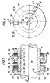
- Figures 1 and 3 generally correspond to Figure 1 and 2 of the aforementioned UK patent application 2282209A and use the same reference numerals.
- a shaft 10 carries a rolling-element bearing 11 and a locking device 12.
- the bearing 11 is composed of an extended inner ring 13 which is to be secured to the shaft 10 with the aid of the device 12 in a non-rotatable manner.
- the ring 13 has an inner bore surface 9 extending parallel to the outer peripheral surface of the shaft 10.
- a set of rolling elements, here in the form of balls 14, is disposed in raceways 15 between the inner ring 13 and an outer ring 16.
- the balls 14 are equi-distantly spaced apart round the raceways 15 with a cage 27 and seals 8 are mounted between the rings 13, 16.
- An axial end region 17 of the inner ring 13 is surrounded by an axial region or portion 18 of a collar 19.
- the collar 19 has an end wall 25 with a bore forming a surface 22 fitted over the shaft 10 with the surface 22 forming a continuation of the inner surface 9 of the ring 13.
- the axial region 17 of the bearing inner ring 13 is relieved to provide an outer surface 20 which is tapered to extend at an angle to the axis of the shaft 10.
- the surface 20 converges towards the shaft axis in the direction of the bearing 11.
- a typical angle for the surface 20 is 3° and generally an angle in the range 1° to 5° is preferred.
- Two screws 21 are located in threaded bores 6 in the axial portion 18 of the collar 19.
- the screws 21 and the bores 6 are offset by the same distance 'd' from radial planes R.
- the radial planes R are spaced apart by 120° and represent the preferred locations of the screws 21 in accordance with UK patent application No. 2282209A.
- the longitudinal axes of the screws 21 now intersect at point L spaced from the axis of rotation P and offset therefrom in an anti clockwise sense relative to the vertical radial plane R as viewed in the direction of arrow II, i.e. in the direction of the axis P from the end wall 25 of the collar 19 and the convergence of the surface 20.
- the screws 21 can be displaced inwardly of the bores 6 to engage on the outer surface 20 of the ring 13.
- the surface 20 has shallow recesses or depressions or blind bores for locating and receiving the ends 23 of the screws 21.
- the inner ring 13 of the bearing 11 and the collar 19 can be easily fitted onto the shaft 10 and the screws 21 are then tightened to some predetermined torque.
- the ends 23 of the screws 21, which can be tapered at the same angle as the surface 20 serve to contact the outer surface 20. When tightened, the ends 23 of the screws 21 press on the outer surface 20 to displace the axial end region 17 of the inner ring 13, and hence the entire inner ring 13, and the axial portion 18 of the collar 19 radially apart.
- FIG. 3 and 4 another locking device 12 is fitted inside a hollow shaft or tube 120.
- the locking device is again composed of a collar 190 and a separate ring 170.
- the collar 190 has an axial region 180 with two angularly offset threaded bores 220 receiving screws 210.
- An end wall 250 of the collar 190 has an outer peripheral surface 280 which is parallel to and confronts an inner surface 300 of the tube 120.
- the ring 170 has an outer peripheral surface 240 which is parallel to and likewise confronts the inner surface 300 of the tube 120 and an inner surface 200 which is tapered at an angle to the axis of the tube 120.
- the surface 200 diverges from the end wall 250 relative to the axis of rotation P.
- the surface 200 can be inclined at an angle of 1° to 5° and preferably 3° to the axis of the tube 120.
- the surface 200 can contain shallow recesses, depressions or blind bores for receiving the ends 230 of the screws 210.
- the screws 210 and the threaded bores 220 are offset by the same distance 'd' from radial planes R.
- the radial planes R are spaced apart by 120° and represent the preferred locations of the screws 210 in accordance with UK patent application 2282209A.
- the longitudinal axes of the screws 210 now intersect at a point L spaced from the axis of rotation P and offset therefrom in an anti clockwise sense relative to the vertical radial plane R as viewed in the direction of arrow IV, i.e. in the direction of the axis P and the divergence of the surface 200 from the end wall 250 of the collar 190.
- the device 12 is locked to the tube 120 by tightening the screws 210 to cause their ends 230 to displace the axial region 180 of the collar 190 and the ring 170 radially apart. This in turn causes diametrically opposed surface contact zones 290, 291 of the surface 280 of the collar end wall 250 and of the surface 240 of the ring 170 to bear against the inner surface 300 of the tube 120 to lock the device in place.
- the ring 170 and the end wall of the collar 190 have radial faces which abut and establish slidable guide surfaces 350 as the screws 210 are tightened or released.
- the device can be used to provide an abutment or location for some other component such as a bearing.
- a device in accordance with the invention does not damage the rotatable component and is easily fitted and removed repeatedly.
- the device also rotates uniformly with the rotatable component without any wobble.
Abstract
Description
Claims (15)
- A device (12) for locking to a component (10) rotatable about an axis (P); said device comprising collar means (19) having an end wall (25) with a bore defining a surface (22) for confronting an outer surface of the rotatable component (10) and an axial region (18) extending axially from the end wall, a ring (13) for disposing between the axial region (18) of the collar means and the component (10), the ring (13) having a first inner surface (9) for confronting the outer surface of the component (10) and a second outer surface (20) which is inclined relative to the axis of rotation (P) to converge with respect to the axis of rotation in a direction away from the end wall (25) and at least two screw-threaded elements (21) received in screw-threaded bores (6) extending through the axial region (18) of the collar means (19) and spaced apart relative to the rotational axis (P) other than at 180°, the arrangement being such that the screw-threaded elements (21) can be tightened to bear into or against the second outer surface (20) of the ring (13) to cause the bore surface (22) of the collar means (19) and the first surface (9) of the ring (13) to act as contact surfaces with respect to the outer surface of the component (10) and exert clamping force on the component at diametrically opposed zones (24, 26); characterized in that the threaded bores (6) are disposed in positions non-radial relative to the rotational axis.
- A device (12) for locking to a hollow component (120) rotatable about an axis (P); said device comprising collar means (190) having an end wall (250) with an outer surface (280) for confronting an inner surface (300) of the component (120) and an axial region (180) extending axially from the end wall (250); a ring (170) for disposing between the axial region (180) of the collar means (190) and the component (120), the ring (170) having a first outer surface (240) for confronting the inner surface (300) of the component and a second inner surface (200) which is inclined relative to the axis of rotation to diverge with respect to the axis of rotation in a direction away from the end wall (250) and at least two screw threaded elements (210) received in screw-threaded bores (220) extending through the axial region (180) of the collar means (190) and spaced apart relative to the rotational axis other than at 180° the arrangement being such that the screw-threaded elements (210) can be tightened to bear into or against the second inner surface (200) of the ring (170) to cause the outer surface (240) of the ring and the outer surface (280) of the end wall (250) of the collar means (190) to act as contact surfaces with respect to the inner surface (300) of the component (120) and exert clamping force on the component at diametrically opposed zones; characterized in that the threaded bores (220) are disposed in non-radial positions relative to the rotational axis (P).
- A device according to claim 1 or 2 wherein the threaded bores (6, 220) have axes which intersect at a location (L) which is offset from the rotational axis (P) and disposed on a radius from the rotational axis, said radius being displaced in an anti-clockwise sense relative to a vertical plane as viewed in the direction of the rotational axis from the end wall (25, 250) of the collar means (19, 190).
- A device according to claim 1, 2 or 3 wherein the confronting surface (22, 280) of the collar means (19, 190) and the first surface (9, 240) of the ring (13, 170) lie closely adjacent to form a continuation of one another.
- A device according to claim 4 wherein between the confronting surface (22, 280) of the collar means and the first surface (9, 240) of the ring (13, 170) there are radially abutting guide surfaces (50, 350) of the collar means and of the ring which slide against one another as the screw-threaded elements (21, 210) are tightened or released.
- A device according to any one of claims 1 to 5 wherein the screw-threaded elements (21, 210) have end surfaces for contacting the second surface (20, 200) of the ring (13, 170) which are inclined relative to the axis of rotation.
- A device according to any one of claims 1 to 6 wherein there are two screw-threaded elements (21, 210).
- A device according to claim 7 when appended to claim 3 wherein the threaded bores (6, 220) for receiving the screw-threaded elements (21, 210) are spaced apart by 120° relative to the location (L) at which the axes of their associated bores (6, 220) intersect.
- A device according to any one of claims 1 to 8 wherein the second surface (20, 200) of the ring (13, 170) has depressions, recesses or blind bores for receiving the ends of the screw-threaded elements (21, 210).
- A device according to any one of claims 3 to 9 when appended to claim 1, wherein the rotatable component is a solid shaft or spindle (10).
- A device according to claim 10 wherein the ring (13) is itself another component of, or part of, some other structure (11) which is to be locked with the device.
- A device according to claim 11 wherein the ring is formed by an extended region of the inner ring of a rolling element bearing (11).
- A device according to claim 2 or any one of claims 3 to 9 when appended to claim 2, wherein the component is a hollow shaft or tube (120).
- A device according to any one of the preceding claims, wherein the second surface (20, 200) of the ring is inclined at an angle of 1° to 5° to the axis of rotation (P).
- An assembly composed of a device according to any one of the preceding claims in combination with the rotatable component (10, 120).
Applications Claiming Priority (3)
| Application Number | Priority Date | Filing Date | Title |
|---|---|---|---|
| GB9602340 | 1996-02-06 | ||
| GBGB9602340.3A GB9602340D0 (en) | 1996-02-06 | 1996-02-06 | Locking device for use with shafts or tubes |
| PCT/GB1997/000336 WO1997029293A1 (en) | 1996-02-06 | 1997-02-06 | Locking device for use with shafts or tubes |
Publications (2)
| Publication Number | Publication Date |
|---|---|
| EP0877868A1 EP0877868A1 (en) | 1998-11-18 |
| EP0877868B1 true EP0877868B1 (en) | 1999-11-17 |
Family
ID=10788172
Family Applications (1)
| Application Number | Title | Priority Date | Filing Date |
|---|---|---|---|
| EP97902489A Expired - Lifetime EP0877868B1 (en) | 1996-02-06 | 1997-02-06 | Locking device for use with shafts or tubes |
Country Status (13)
| Country | Link |
|---|---|
| EP (1) | EP0877868B1 (en) |
| JP (1) | JP3984291B2 (en) |
| CN (1) | CN1098424C (en) |
| AT (1) | ATE186768T1 (en) |
| AU (1) | AU708944B2 (en) |
| CA (1) | CA2244068C (en) |
| DE (1) | DE69700808T2 (en) |
| ES (1) | ES2139439T3 (en) |
| GB (2) | GB9602340D0 (en) |
| GR (1) | GR3031898T3 (en) |
| HK (1) | HK1002289A1 (en) |
| PT (1) | PT877868E (en) |
| WO (1) | WO1997029293A1 (en) |
Families Citing this family (1)
| Publication number | Priority date | Publication date | Assignee | Title |
|---|---|---|---|---|
| CN110319113B (en) * | 2019-07-06 | 2020-10-16 | 蚌埠飞宇轴承有限公司 | Bearing |
Family Cites Families (7)
| Publication number | Priority date | Publication date | Assignee | Title |
|---|---|---|---|---|
| US2739830A (en) * | 1951-02-23 | 1956-03-27 | Dodge Mfg Corp | Shaft collars |
| US3598432A (en) * | 1969-10-20 | 1971-08-10 | Designatronics Inc | Hub clamp |
| EP0088589A1 (en) * | 1982-03-10 | 1983-09-14 | Eaton Corporation | Mounting shaft and adaptor for viscous coupling |
| DE3804655A1 (en) * | 1988-02-15 | 1989-08-24 | Skf Bewegungstechnik Gmbh | Device for positive fastening |
| DE3822472A1 (en) * | 1988-07-02 | 1990-01-04 | Neuweg Fertigung Gmbh | Radial rolling bearing |
| US5269118A (en) * | 1992-07-14 | 1993-12-14 | Continental White Cap, Inc. | Shaft locking device |
| GB9319880D0 (en) * | 1993-09-27 | 1993-11-10 | Rhp Bearings Ltd | Locking device for use with shafts of tubes |
-
1996
- 1996-02-06 GB GBGB9602340.3A patent/GB9602340D0/en active Pending
-
1997
- 1997-02-06 ES ES97902489T patent/ES2139439T3/en not_active Expired - Lifetime
- 1997-02-06 DE DE69700808T patent/DE69700808T2/en not_active Expired - Lifetime
- 1997-02-06 EP EP97902489A patent/EP0877868B1/en not_active Expired - Lifetime
- 1997-02-06 CA CA002244068A patent/CA2244068C/en not_active Expired - Lifetime
- 1997-02-06 PT PT97902489T patent/PT877868E/en unknown
- 1997-02-06 AU AU16121/97A patent/AU708944B2/en not_active Expired
- 1997-02-06 JP JP52828697A patent/JP3984291B2/en not_active Expired - Lifetime
- 1997-02-06 AT AT97902489T patent/ATE186768T1/en not_active IP Right Cessation
- 1997-02-06 GB GB9702421A patent/GB2310027B/en not_active Expired - Lifetime
- 1997-02-06 CN CN97193651A patent/CN1098424C/en not_active Expired - Lifetime
- 1997-02-06 WO PCT/GB1997/000336 patent/WO1997029293A1/en active IP Right Grant
-
1998
- 1998-02-12 HK HK98101130A patent/HK1002289A1/en not_active IP Right Cessation
-
1999
- 1999-11-18 GR GR990402991T patent/GR3031898T3/en unknown
Also Published As
| Publication number | Publication date |
|---|---|
| CN1098424C (en) | 2003-01-08 |
| CA2244068A1 (en) | 1997-08-14 |
| EP0877868A1 (en) | 1998-11-18 |
| CA2244068C (en) | 2002-06-11 |
| JP2000504814A (en) | 2000-04-18 |
| ATE186768T1 (en) | 1999-12-15 |
| AU1612197A (en) | 1997-08-28 |
| WO1997029293A1 (en) | 1997-08-14 |
| CN1215454A (en) | 1999-04-28 |
| GB2310027B (en) | 1998-05-06 |
| ES2139439T3 (en) | 2000-02-01 |
| HK1002289A1 (en) | 1998-08-14 |
| DE69700808T2 (en) | 2000-07-20 |
| GB9702421D0 (en) | 1997-03-26 |
| GB2310027A (en) | 1997-08-13 |
| AU708944B2 (en) | 1999-08-19 |
| PT877868E (en) | 2000-05-31 |
| GB9602340D0 (en) | 1996-04-03 |
| GR3031898T3 (en) | 2000-02-29 |
| JP3984291B2 (en) | 2007-10-03 |
| DE69700808D1 (en) | 1999-12-23 |
Similar Documents
| Publication | Publication Date | Title |
|---|---|---|
| US5564839A (en) | Bearing unit for wheel with speed sensor | |
| US4792244A (en) | Ceramic bearing construction | |
| CA2565903C (en) | Taper lock bearing assembly | |
| AU689993B2 (en) | Bearing assembly utilizing improved clamping arrangement | |
| US4304502A (en) | Torque and thrust transmitting bushings | |
| US20060291764A1 (en) | Clamping arrangement for securing an annular component to a shaft | |
| US6361243B1 (en) | Mounting device | |
| US4865336A (en) | Apparatus for securing a cutting tool in a tool holder and machine tools employing the same | |
| US5269607A (en) | Bearing assembly with locking device | |
| EP0967404B1 (en) | Mounting device for a bearing unit | |
| US5678949A (en) | Locking device for use with shafts or tubes | |
| GB2040393A (en) | Torque-transmitting and axially displaceable mounting | |
| US6092956A (en) | Locking device for use with shafts or tubes | |
| GB2125512A (en) | A pulley assembly | |
| EP0877868B1 (en) | Locking device for use with shafts or tubes | |
| US5228787A (en) | Bearing assembly with locking device | |
| US5622373A (en) | Chucking device | |
| US3907387A (en) | Anti-friction bearing | |
| US4820060A (en) | Spacer bushing for two-row ball bearing | |
| EP0741631B1 (en) | Positive radial location of wheels on spindles |
Legal Events
| Date | Code | Title | Description |
|---|---|---|---|
| PUAI | Public reference made under article 153(3) epc to a published international application that has entered the european phase |
Free format text: ORIGINAL CODE: 0009012 |
|
| 17P | Request for examination filed |
Effective date: 19980721 |
|
| AK | Designated contracting states |
Kind code of ref document: A1 Designated state(s): AT BE CH DE DK ES FI FR GR IE IT LI NL PT SE |
|
| GRAG | Despatch of communication of intention to grant |
Free format text: ORIGINAL CODE: EPIDOS AGRA |
|
| 17Q | First examination report despatched |
Effective date: 19990114 |
|
| GRAG | Despatch of communication of intention to grant |
Free format text: ORIGINAL CODE: EPIDOS AGRA |
|
| GRAH | Despatch of communication of intention to grant a patent |
Free format text: ORIGINAL CODE: EPIDOS IGRA |
|
| GRAH | Despatch of communication of intention to grant a patent |
Free format text: ORIGINAL CODE: EPIDOS IGRA |
|
| GRAA | (expected) grant |
Free format text: ORIGINAL CODE: 0009210 |
|
| AK | Designated contracting states |
Kind code of ref document: B1 Designated state(s): AT BE CH DE DK ES FI FR GR IE IT LI NL PT SE |
|
| REF | Corresponds to: |
Ref document number: 186768 Country of ref document: AT Date of ref document: 19991215 Kind code of ref document: T |
|
| REG | Reference to a national code |
Ref country code: CH Ref legal event code: EP |
|
| REF | Corresponds to: |
Ref document number: 69700808 Country of ref document: DE Date of ref document: 19991223 |
|
| ITF | It: translation for a ep patent filed |
Owner name: ING. C. GREGORJ S.P.A. |
|
| REG | Reference to a national code |
Ref country code: IE Ref legal event code: FG4D |
|
| REG | Reference to a national code |
Ref country code: ES Ref legal event code: FG2A Ref document number: 2139439 Country of ref document: ES Kind code of ref document: T3 |
|
| REG | Reference to a national code |
Ref country code: CH Ref legal event code: NV Representative=s name: PATENTANWALTSBUREAU R. A. MASPOLI |
|
| ET | Fr: translation filed | ||
| REG | Reference to a national code |
Ref country code: DK Ref legal event code: T3 |
|
| REG | Reference to a national code |
Ref country code: PT Ref legal event code: SC4A Free format text: AVAILABILITY OF NATIONAL TRANSLATION Effective date: 20000215 |
|
| PLBE | No opposition filed within time limit |
Free format text: ORIGINAL CODE: 0009261 |
|
| STAA | Information on the status of an ep patent application or granted ep patent |
Free format text: STATUS: NO OPPOSITION FILED WITHIN TIME LIMIT |
|
| 26N | No opposition filed | ||
| PGFP | Annual fee paid to national office [announced via postgrant information from national office to epo] |
Ref country code: FI Payment date: 20010122 Year of fee payment: 5 |
|
| PGFP | Annual fee paid to national office [announced via postgrant information from national office to epo] |
Ref country code: PT Payment date: 20010123 Year of fee payment: 5 |
|
| PGFP | Annual fee paid to national office [announced via postgrant information from national office to epo] |
Ref country code: IE Payment date: 20010124 Year of fee payment: 5 |
|
| PGFP | Annual fee paid to national office [announced via postgrant information from national office to epo] |
Ref country code: BE Payment date: 20010130 Year of fee payment: 5 |
|
| PGFP | Annual fee paid to national office [announced via postgrant information from national office to epo] |
Ref country code: GR Payment date: 20010206 Year of fee payment: 5 |
|
| PGFP | Annual fee paid to national office [announced via postgrant information from national office to epo] |
Ref country code: CH Payment date: 20010213 Year of fee payment: 5 |
|
| PGFP | Annual fee paid to national office [announced via postgrant information from national office to epo] |
Ref country code: SE Payment date: 20010215 Year of fee payment: 5 |
|
| PGFP | Annual fee paid to national office [announced via postgrant information from national office to epo] |
Ref country code: DK Payment date: 20010216 Year of fee payment: 5 |
|
| PGFP | Annual fee paid to national office [announced via postgrant information from national office to epo] |
Ref country code: AT Payment date: 20010223 Year of fee payment: 5 |
|
| PGFP | Annual fee paid to national office [announced via postgrant information from national office to epo] |
Ref country code: NL Payment date: 20010228 Year of fee payment: 5 |
|
| PG25 | Lapsed in a contracting state [announced via postgrant information from national office to epo] |
Ref country code: IE Free format text: LAPSE BECAUSE OF NON-PAYMENT OF DUE FEES Effective date: 20020206 Ref country code: FI Free format text: LAPSE BECAUSE OF NON-PAYMENT OF DUE FEES Effective date: 20020206 Ref country code: AT Free format text: LAPSE BECAUSE OF NON-PAYMENT OF DUE FEES Effective date: 20020206 |
|
| PG25 | Lapsed in a contracting state [announced via postgrant information from national office to epo] |
Ref country code: SE Free format text: LAPSE BECAUSE OF NON-PAYMENT OF DUE FEES Effective date: 20020207 |
|
| PG25 | Lapsed in a contracting state [announced via postgrant information from national office to epo] |
Ref country code: LI Free format text: LAPSE BECAUSE OF NON-PAYMENT OF DUE FEES Effective date: 20020228 Ref country code: DK Free format text: LAPSE BECAUSE OF NON-PAYMENT OF DUE FEES Effective date: 20020228 Ref country code: CH Free format text: LAPSE BECAUSE OF NON-PAYMENT OF DUE FEES Effective date: 20020228 Ref country code: BE Free format text: LAPSE BECAUSE OF NON-PAYMENT OF DUE FEES Effective date: 20020228 |
|
| BERE | Be: lapsed |
Owner name: NSK RHP EUROPEAN TECHNOLOGY CO. LTD Effective date: 20020228 |
|
| PG25 | Lapsed in a contracting state [announced via postgrant information from national office to epo] |
Ref country code: PT Free format text: LAPSE BECAUSE OF NON-PAYMENT OF DUE FEES Effective date: 20020831 |
|
| PG25 | Lapsed in a contracting state [announced via postgrant information from national office to epo] |
Ref country code: NL Free format text: LAPSE BECAUSE OF NON-PAYMENT OF DUE FEES Effective date: 20020901 |
|
| PG25 | Lapsed in a contracting state [announced via postgrant information from national office to epo] |
Ref country code: GR Free format text: LAPSE BECAUSE OF NON-PAYMENT OF DUE FEES Effective date: 20020909 |
|
| EUG | Se: european patent has lapsed |
Ref document number: 97902489.0 |
|
| REG | Reference to a national code |
Ref country code: CH Ref legal event code: PL |
|
| REG | Reference to a national code |
Ref country code: DK Ref legal event code: EBP |
|
| NLV4 | Nl: lapsed or anulled due to non-payment of the annual fee |
Effective date: 20020901 |
|
| REG | Reference to a national code |
Ref country code: PT Ref legal event code: MM4A Free format text: LAPSE DUE TO NON-PAYMENT OF FEES Effective date: 20020831 |
|
| REG | Reference to a national code |
Ref country code: IE Ref legal event code: MM4A |
|
| REG | Reference to a national code |
Ref country code: FR Ref legal event code: TP |
|
| REG | Reference to a national code |
Ref country code: FR Ref legal event code: PLFP Year of fee payment: 20 |
|
| PGFP | Annual fee paid to national office [announced via postgrant information from national office to epo] |
Ref country code: IT Payment date: 20160223 Year of fee payment: 20 Ref country code: ES Payment date: 20160226 Year of fee payment: 20 Ref country code: DE Payment date: 20160226 Year of fee payment: 20 |
|
| PGFP | Annual fee paid to national office [announced via postgrant information from national office to epo] |
Ref country code: FR Payment date: 20160217 Year of fee payment: 20 |
|
| REG | Reference to a national code |
Ref country code: DE Ref legal event code: R071 Ref document number: 69700808 Country of ref document: DE |
|
| REG | Reference to a national code |
Ref country code: ES Ref legal event code: FD2A Effective date: 20170526 |
|
| PG25 | Lapsed in a contracting state [announced via postgrant information from national office to epo] |
Ref country code: ES Free format text: LAPSE BECAUSE OF EXPIRATION OF PROTECTION Effective date: 20170207 |