EP0877394B1 - Composite magnetic tape - Google Patents
Composite magnetic tape Download PDFInfo
- Publication number
- EP0877394B1 EP0877394B1 EP97937857A EP97937857A EP0877394B1 EP 0877394 B1 EP0877394 B1 EP 0877394B1 EP 97937857 A EP97937857 A EP 97937857A EP 97937857 A EP97937857 A EP 97937857A EP 0877394 B1 EP0877394 B1 EP 0877394B1
- Authority
- EP
- European Patent Office
- Prior art keywords
- tape
- composite magnetic
- layer
- magnetic body
- magnetic tape
- Prior art date
- Legal status (The legal status is an assumption and is not a legal conclusion. Google has not performed a legal analysis and makes no representation as to the accuracy of the status listed.)
- Expired - Lifetime
Links
- 239000002131 composite material Substances 0.000 title claims description 42
- 239000010410 layer Substances 0.000 claims description 30
- 238000003466 welding Methods 0.000 claims description 16
- 239000006247 magnetic powder Substances 0.000 claims description 12
- 239000011230 binding agent Substances 0.000 claims description 9
- 239000012790 adhesive layer Substances 0.000 claims description 8
- 239000010409 thin film Substances 0.000 claims description 7
- 239000003795 chemical substances by application Substances 0.000 claims description 6
- 239000004020 conductor Substances 0.000 claims description 5
- 230000035699 permeability Effects 0.000 claims description 4
- 229920001971 elastomer Polymers 0.000 claims description 2
- 239000000806 elastomer Substances 0.000 claims description 2
- 239000010408 film Substances 0.000 claims description 2
- 239000000843 powder Substances 0.000 claims description 2
- PXHVJJICTQNCMI-UHFFFAOYSA-N Nickel Chemical compound [Ni] PXHVJJICTQNCMI-UHFFFAOYSA-N 0.000 description 12
- 239000002184 metal Substances 0.000 description 10
- 229910052751 metal Inorganic materials 0.000 description 10
- 230000005672 electromagnetic field Effects 0.000 description 9
- 230000008878 coupling Effects 0.000 description 7
- 238000010168 coupling process Methods 0.000 description 7
- 238000005859 coupling reaction Methods 0.000 description 7
- 238000002834 transmittance Methods 0.000 description 7
- 239000002390 adhesive tape Substances 0.000 description 6
- 229910052759 nickel Inorganic materials 0.000 description 6
- 238000000137 annealing Methods 0.000 description 5
- 229910052802 copper Inorganic materials 0.000 description 4
- 239000010949 copper Substances 0.000 description 4
- 230000000694 effects Effects 0.000 description 4
- 238000005259 measurement Methods 0.000 description 4
- 238000000034 method Methods 0.000 description 4
- 239000004709 Chlorinated polyethylene Substances 0.000 description 3
- 239000000853 adhesive Substances 0.000 description 3
- 230000001070 adhesive effect Effects 0.000 description 3
- 230000000052 comparative effect Effects 0.000 description 3
- 238000010586 diagram Methods 0.000 description 3
- 230000012447 hatching Effects 0.000 description 3
- 230000005855 radiation Effects 0.000 description 3
- 238000004804 winding Methods 0.000 description 3
- 229910021364 Al-Si alloy Inorganic materials 0.000 description 2
- XKRFYHLGVUSROY-UHFFFAOYSA-N Argon Chemical compound [Ar] XKRFYHLGVUSROY-UHFFFAOYSA-N 0.000 description 2
- IJGRMHOSHXDMSA-UHFFFAOYSA-N Atomic nitrogen Chemical compound N#N IJGRMHOSHXDMSA-UHFFFAOYSA-N 0.000 description 2
- 239000003822 epoxy resin Substances 0.000 description 2
- 230000001939 inductive effect Effects 0.000 description 2
- 229920000647 polyepoxide Polymers 0.000 description 2
- 229920001225 polyester resin Polymers 0.000 description 2
- 239000004645 polyester resin Substances 0.000 description 2
- 229920005989 resin Polymers 0.000 description 2
- 239000011347 resin Substances 0.000 description 2
- 229910001030 Iron–nickel alloy Inorganic materials 0.000 description 1
- 229920000459 Nitrile rubber Polymers 0.000 description 1
- 239000004952 Polyamide Substances 0.000 description 1
- 238000010521 absorption reaction Methods 0.000 description 1
- 229910045601 alloy Inorganic materials 0.000 description 1
- 239000000956 alloy Substances 0.000 description 1
- 229910052786 argon Inorganic materials 0.000 description 1
- QVGXLLKOCUKJST-UHFFFAOYSA-N atomic oxygen Chemical compound [O] QVGXLLKOCUKJST-UHFFFAOYSA-N 0.000 description 1
- 239000012461 cellulose resin Substances 0.000 description 1
- 150000001879 copper Chemical class 0.000 description 1
- 238000007772 electroless plating Methods 0.000 description 1
- 239000011888 foil Substances 0.000 description 1
- 239000007789 gas Substances 0.000 description 1
- 238000010438 heat treatment Methods 0.000 description 1
- 238000009413 insulation Methods 0.000 description 1
- 230000009545 invasion Effects 0.000 description 1
- 230000007257 malfunction Effects 0.000 description 1
- DOTMOQHOJINYBL-UHFFFAOYSA-N molecular nitrogen;molecular oxygen Chemical compound N#N.O=O DOTMOQHOJINYBL-UHFFFAOYSA-N 0.000 description 1
- 229910052757 nitrogen Inorganic materials 0.000 description 1
- 239000001301 oxygen Substances 0.000 description 1
- 229910052760 oxygen Inorganic materials 0.000 description 1
- 239000002245 particle Substances 0.000 description 1
- 229920002037 poly(vinyl butyral) polymer Polymers 0.000 description 1
- 229920002647 polyamide Polymers 0.000 description 1
- 229920006122 polyamide resin Polymers 0.000 description 1
- 229920006149 polyester-amide block copolymer Polymers 0.000 description 1
- 229920000642 polymer Polymers 0.000 description 1
- 229920005749 polyurethane resin Polymers 0.000 description 1
- 239000004800 polyvinyl chloride Substances 0.000 description 1
- 229920000915 polyvinyl chloride Polymers 0.000 description 1
- 238000001228 spectrum Methods 0.000 description 1
- 229920003048 styrene butadiene rubber Polymers 0.000 description 1
- 230000001629 suppression Effects 0.000 description 1
- 229920005992 thermoplastic resin Polymers 0.000 description 1
- 239000012808 vapor phase Substances 0.000 description 1
Images


Classifications
-
- H—ELECTRICITY
- H01—ELECTRIC ELEMENTS
- H01F—MAGNETS; INDUCTANCES; TRANSFORMERS; SELECTION OF MATERIALS FOR THEIR MAGNETIC PROPERTIES
- H01F1/00—Magnets or magnetic bodies characterised by the magnetic materials therefor; Selection of materials for their magnetic properties
- H01F1/01—Magnets or magnetic bodies characterised by the magnetic materials therefor; Selection of materials for their magnetic properties of inorganic materials
- H01F1/03—Magnets or magnetic bodies characterised by the magnetic materials therefor; Selection of materials for their magnetic properties of inorganic materials characterised by their coercivity
- H01F1/12—Magnets or magnetic bodies characterised by the magnetic materials therefor; Selection of materials for their magnetic properties of inorganic materials characterised by their coercivity of soft-magnetic materials
- H01F1/14—Magnets or magnetic bodies characterised by the magnetic materials therefor; Selection of materials for their magnetic properties of inorganic materials characterised by their coercivity of soft-magnetic materials metals or alloys
- H01F1/20—Magnets or magnetic bodies characterised by the magnetic materials therefor; Selection of materials for their magnetic properties of inorganic materials characterised by their coercivity of soft-magnetic materials metals or alloys in the form of particles, e.g. powder
- H01F1/22—Magnets or magnetic bodies characterised by the magnetic materials therefor; Selection of materials for their magnetic properties of inorganic materials characterised by their coercivity of soft-magnetic materials metals or alloys in the form of particles, e.g. powder pressed, sintered, or bound together
- H01F1/24—Magnets or magnetic bodies characterised by the magnetic materials therefor; Selection of materials for their magnetic properties of inorganic materials characterised by their coercivity of soft-magnetic materials metals or alloys in the form of particles, e.g. powder pressed, sintered, or bound together the particles being insulated
-
- H—ELECTRICITY
- H05—ELECTRIC TECHNIQUES NOT OTHERWISE PROVIDED FOR
- H05K—PRINTED CIRCUITS; CASINGS OR CONSTRUCTIONAL DETAILS OF ELECTRIC APPARATUS; MANUFACTURE OF ASSEMBLAGES OF ELECTRICAL COMPONENTS
- H05K9/00—Screening of apparatus or components against electric or magnetic fields
- H05K9/0073—Shielding materials
- H05K9/0081—Electromagnetic shielding materials, e.g. EMI, RFI shielding
- H05K9/0088—Electromagnetic shielding materials, e.g. EMI, RFI shielding comprising a plurality of shielding layers; combining different shielding material structure
-
- H—ELECTRICITY
- H01—ELECTRIC ELEMENTS
- H01F—MAGNETS; INDUCTANCES; TRANSFORMERS; SELECTION OF MATERIALS FOR THEIR MAGNETIC PROPERTIES
- H01F1/00—Magnets or magnetic bodies characterised by the magnetic materials therefor; Selection of materials for their magnetic properties
- H01F1/01—Magnets or magnetic bodies characterised by the magnetic materials therefor; Selection of materials for their magnetic properties of inorganic materials
- H01F1/03—Magnets or magnetic bodies characterised by the magnetic materials therefor; Selection of materials for their magnetic properties of inorganic materials characterised by their coercivity
- H01F1/12—Magnets or magnetic bodies characterised by the magnetic materials therefor; Selection of materials for their magnetic properties of inorganic materials characterised by their coercivity of soft-magnetic materials
- H01F1/14—Magnets or magnetic bodies characterised by the magnetic materials therefor; Selection of materials for their magnetic properties of inorganic materials characterised by their coercivity of soft-magnetic materials metals or alloys
- H01F1/20—Magnets or magnetic bodies characterised by the magnetic materials therefor; Selection of materials for their magnetic properties of inorganic materials characterised by their coercivity of soft-magnetic materials metals or alloys in the form of particles, e.g. powder
- H01F1/22—Magnets or magnetic bodies characterised by the magnetic materials therefor; Selection of materials for their magnetic properties of inorganic materials characterised by their coercivity of soft-magnetic materials metals or alloys in the form of particles, e.g. powder pressed, sintered, or bound together
- H01F1/24—Magnets or magnetic bodies characterised by the magnetic materials therefor; Selection of materials for their magnetic properties of inorganic materials characterised by their coercivity of soft-magnetic materials metals or alloys in the form of particles, e.g. powder pressed, sintered, or bound together the particles being insulated
- H01F1/26—Magnets or magnetic bodies characterised by the magnetic materials therefor; Selection of materials for their magnetic properties of inorganic materials characterised by their coercivity of soft-magnetic materials metals or alloys in the form of particles, e.g. powder pressed, sintered, or bound together the particles being insulated by macromolecular organic substances
-
- Y—GENERAL TAGGING OF NEW TECHNOLOGICAL DEVELOPMENTS; GENERAL TAGGING OF CROSS-SECTIONAL TECHNOLOGIES SPANNING OVER SEVERAL SECTIONS OF THE IPC; TECHNICAL SUBJECTS COVERED BY FORMER USPC CROSS-REFERENCE ART COLLECTIONS [XRACs] AND DIGESTS
- Y10—TECHNICAL SUBJECTS COVERED BY FORMER USPC
- Y10S—TECHNICAL SUBJECTS COVERED BY FORMER USPC CROSS-REFERENCE ART COLLECTIONS [XRACs] AND DIGESTS
- Y10S428/00—Stock material or miscellaneous articles
- Y10S428/90—Magnetic feature
-
- Y—GENERAL TAGGING OF NEW TECHNOLOGICAL DEVELOPMENTS; GENERAL TAGGING OF CROSS-SECTIONAL TECHNOLOGIES SPANNING OVER SEVERAL SECTIONS OF THE IPC; TECHNICAL SUBJECTS COVERED BY FORMER USPC CROSS-REFERENCE ART COLLECTIONS [XRACs] AND DIGESTS
- Y10—TECHNICAL SUBJECTS COVERED BY FORMER USPC
- Y10T—TECHNICAL SUBJECTS COVERED BY FORMER US CLASSIFICATION
- Y10T428/00—Stock material or miscellaneous articles
- Y10T428/24—Structurally defined web or sheet [e.g., overall dimension, etc.]
- Y10T428/24628—Nonplanar uniform thickness material
-
- Y—GENERAL TAGGING OF NEW TECHNOLOGICAL DEVELOPMENTS; GENERAL TAGGING OF CROSS-SECTIONAL TECHNOLOGIES SPANNING OVER SEVERAL SECTIONS OF THE IPC; TECHNICAL SUBJECTS COVERED BY FORMER USPC CROSS-REFERENCE ART COLLECTIONS [XRACs] AND DIGESTS
- Y10—TECHNICAL SUBJECTS COVERED BY FORMER USPC
- Y10T—TECHNICAL SUBJECTS COVERED BY FORMER US CLASSIFICATION
- Y10T428/00—Stock material or miscellaneous articles
- Y10T428/28—Web or sheet containing structurally defined element or component and having an adhesive outermost layer
Definitions
- the present invention relates to means for electromagnetic shielding and electromagnetic noise suppression in the electric and electronic industries and, in particular, to a tape to be used therefor.
- tapes using Cu, Al or stainless sheets have been known for magnetic shielding or electric connection.
- Such a tape has a width of about 10 to 20mm and a thickness of about 0.1 to 0.3mm, and is wound in a belt fashion.
- Adhesive tapes obtained by applying an adhesive to the foregoing Cu, Al or stainless tapes have also been known.
- self-welding tapes those obtained by applying a self-welding agent, such as polyester or polyamide, to the foregoing Cu, Al or stainless tapes have been known.
- shield plates conductor plates
- the foregoing conventional tape is small in magnetic shield effect relative to high frequency waves of portable telephones, PHS's, transceivers, electronic equipments or the like, particularly, electromagnetic waves at several hundred to thousand MHz bands. Therefore, there has been necessity for such tapes as having the magnetic shield effect over the wide frequency band, instead of the conventional tapes.
- the tape or shield plate may function as an antenna or secondary radiant noise due to reflection may be generated, so as to cause an influence to other devices in the same equipment.
- a composite magnetic tape according to the preamble of claim 1 can be taken.
- the soft magnetic powder is subjected to a heat treatment preferably carried out in an inert atmosphere such as nitrogen and argon.
- a composite magnetic tape can be taken which comprises a thin film of a composite magnetic body formed by dispersing soft magnetic powder into an organic binding agent.
- the present invention provides a composite magnetic tape as recited in claim 1.
- the shown embodiment shows a roll 1 formed by winding a tape 11 composed of only a thin film of a composite magnetic body formed by dispersing soft magnetic powder into an organic binding agent.
- a section of the tape 11 has a structure in which the soft magnetic powder (shown by dots) is dispersed into a layer of the organic binding agent (shown by hatching of oblique thick lines).
- an Fe-Al-Si alloy or an Fe-Ni alloy having a large high frequency permeability can be cited.
- thermoplastic resin such as polyester resin, polyvinyl chloride resin, polyvinyl butyral resin, polyurethane resin, cellulose resin, nitrile-butadiene rubber or styrene-butadiene rubber, or a polymer thereof can be cited.
- chlorinated polyethylene can also be used.
- an elastomer having elasticity is suitable for tape.
- the shown embodiment shows a roll 2 formed by winding an adhesive tape 21 which is obtained by applying a thin layer 12 (in the figure, shown by hatching of horizontal lines) of an adhesive onto the surface of a tape 11 constituted of a thin film of a composite magnetic body formed by dispersing soft magnetic powder into an organic binding agent.
- the shown embodiment shows a roll 3 formed by winding a self-welding tape 31 which is obtained by applying a thin layer 13 (in the figure, shown by hatching of mesh) of a self-welding agent onto the surface of a tape 11 constituted of a thin film of a composite magnetic body formed by dispersing soft magnetic powder into an organic binding agent.
- Fig. 4 shows an example in which a thin film forming a tape has a stacked structure of layers of composite magnetic bodies and a metal layer.
- the shown example is an adhesive tape 41 of a structure, wherein a metal layer 14 is interposed between tape layers 11 and 11' composed of composite magnetic bodies, and an adhesive layer 12 is provided on the surface of the tape layer 11 composed of the composite magnetic body.
- metal layer a metal foil, a net made of metal wires (metal mesh), an electroless plating layer, a deposited metal layer or the like may be used.
- a self-welding agent layer 13 may be used instead of the adhesive layer 12 so as to form a self-welding tape.
- (13) is added adjacent to reference sign 12 in the figure.
- the adhesive layer 12 and the self-welding agent layer 13 both can be omitted.
- One composite magnetic layer is acceptable.
- a plurality of composite magnetic layers and metal layers may be stacked.
- Table 1 shows an example of the composite magnetic body used in the embodiments shown in Figs. 1 to 4.
- Table 1 Soft magnetic powder Fe-Al-Si alloy 80 weight parts Average particle diameter: 45 ⁇ m Aspect ratio: >5 Annealing: Ar atmosphere 650°C, 2 hours Organic binding agent (chlorinated polyethylene) 20 weight parts
- the composite magnetic body was produced in the following manner.
- the soft magnetic powder obtained by a normal method was vapor-phase oxidized in an atmosphere of nitrogen-oxygen mixed gas at a 20% oxygen partial pressure, and oxide films were formed on the surfaces thereof.
- the powder and chlorinated polyethylene were heated and kneaded, and then formed under pressure to obtain a formed body of the composite magnetic body.
- the surface resistance of the composite magnetic body was measured and found to be 1 x 10 6 ⁇ .
- Fig. 5 shows a measured ⁇ -f (permeability-frequency) characteristic of the foregoing composite magnetic body. Solid lines represent ⁇ characteristics after annealing, while broken lines represent ⁇ characteristics before annealing. As shown in Fig. 5, the composite magnetic body before annealing has peaks in ⁇ " (complex permeability) which appear following the magnetic resonance, and it is observed that the magnetic resonance occurs at two points. After it is subjected to the annealing, it is seen that ⁇ " reveals high values over a wide range, and ⁇ " also reveals large values at high frequencies.
- ⁇ " complex permeability
- the composite magnetic body of Table 1 was formed into two layers 11 and 11' and a nickel mesh was interposed therebetween as a conductor layer 14, to form a multilayered structure so that a tape composed of a thin belt 41 having a mean dimension of 15mm and a mean thickness of 0.3mm was formed.
- either the adhesive layer 12 or the self-welding layer (13) was used.
- a tape 11 having a mean width of 15mm and a mean thickness of 0.3mm was formed. Then, as shown in Fig. 2, an adhesive 12 having electrically insulating and conductive properties was applied to the tape 11 to obtain an adhesive tape 21.
- the composite magnetic body of Table 1 was formed into two layers 11 and 11' and a nickel mesh was interposed therebetween as a conductor layer 14, to form a multilayered structure so that a tape composed of a thin belt having a mean width of 15mm and a mean thickness of 0.3mm was formed.
- An adhesive layer 12 was applied to the surface of the tape to obtain an adhesive tape 41.
- a tape 11 having a mean width of 15mm and a mean thickness of 0.3mm was formed. Then, as shown in Fig. 3, a self-welding layer 13 made of epoxy resin as a main component was applied to the tape 11 to obtain a self-welding tape 31.
- the main component of the self-welding layer polyamide resin, polyester resin or the like may be used other than the epoxy resin.
- the composite magnetic body of Table 1 was formed into two layers 11 and 11' and a nickel mesh was interposed therebetween as a conductor layer 14, to form a multilayered structure so that a tape composed of a thin belt having a mean width of 15mm and a mean thickness of 0.3mm was formed.
- the foregoing self-welding agent 13 was applied to the tape to obtain a self-welding tape 41.
- the nickel mesh of 100 meshes with t 0.05mm was used.
- a sample 20 was disposed between the electromagnetic field transmitting micro-loop antenna 23 and the electromagnetic field receiving micro-loop antenna 24.
- the sample 20 was disposed so that one side thereof confronts the electromagnetic field transmitting micro-loop antenna 23 and the electromagnetic field receiving micro-loop antenna 24.
- the transmittance attenuation levels and the coupling levels measured by the foregoing method are shown in Figs. 6 and 7, respectively.
- the transmittance attenuation levels and the coupling levels are both reduced.
- the comparative example it is seen that although the transmittance attenuation level is much reduced, the coupling level is increased. From the foregoing results, it is seen that the composite magnetic tape according to the present invention can effectively remove the radiant noise without inducing the secondary radiant noise due to reflection.
- a tape which can prevent high frequency radiation and reflection noise easily, like an insulating tape for electric insulation, without inducing secondary radiation, using a tape, an adhesive tape or a self-welding tape constituted of a composite magnetic body which can keep an electromagnetic absorption effect even at a high frequency band.
Landscapes
- Engineering & Computer Science (AREA)
- Physics & Mathematics (AREA)
- Chemical & Material Sciences (AREA)
- Dispersion Chemistry (AREA)
- Power Engineering (AREA)
- Electromagnetism (AREA)
- Microelectronics & Electronic Packaging (AREA)
- Spectroscopy & Molecular Physics (AREA)
- Shielding Devices Or Components To Electric Or Magnetic Fields (AREA)
- Soft Magnetic Materials (AREA)
Description
- The present invention relates to means for electromagnetic shielding and electromagnetic noise suppression in the electric and electronic industries and, in particular, to a tape to be used therefor.
- Conventionally, in the electric and electronic industries, tapes using Cu, Al or stainless sheets have been known for magnetic shielding or electric connection. Such a tape has a width of about 10 to 20mm and a thickness of about 0.1 to 0.3mm, and is wound in a belt fashion. Adhesive tapes obtained by applying an adhesive to the foregoing Cu, Al or stainless tapes have also been known. Further, as self-welding tapes, those obtained by applying a self-welding agent, such as polyester or polyamide, to the foregoing Cu, Al or stainless tapes have been known.
- There is a possibility that electronic equipments may malfunction due to undesired electromagnetic waves (electromagnetic noise) from the exterior. As such electromagnetic noise, there are electromagnetic waves caused by other communications, undesired electromagnetic waves radiated from various kinds of equipments and devices used therein, and electromagnetic waves due to reflection. Therefore, shielding is essential in electronic equipments and various kinds of equipments radiating undesired electromagnetic waves for preventing radiation of the electromagnetic waves and invasion of the electromagnetic waves from the exterior.
- In view of this, conductor plates (shield plates) have been used in these equipments. If the shield plates are used, the number of parts of the equipment is increased to cause high cost.
- Accordingly, for realizing a shield effect easily and cheaply, it is considered to use the foregoing tapes.
- However, the foregoing conventional tape is small in magnetic shield effect relative to high frequency waves of portable telephones, PHS's, transceivers, electronic equipments or the like, particularly, electromagnetic waves at several hundred to thousand MHz bands. Therefore, there has been necessity for such tapes as having the magnetic shield effect over the wide frequency band, instead of the conventional tapes.
- Further, if the foregoing tape or shield plate is used carelessly, there is raised a problem that the tape or shield plate may function as an antenna or secondary radiant noise due to reflection may be generated, so as to cause an influence to other devices in the same equipment.
- From EP 0 301 561 A2 (corresponding to JP 1/205404 A) a composite magnetic tape according to the preamble of claim 1 can be taken. The soft magnetic powder is subjected to a heat treatment preferably carried out in an inert atmosphere such as nitrogen and argon.
- From JP 06-292630 A a composite magnetic tape can be taken which comprises a thin film of a composite magnetic body formed by dispersing soft magnetic powder into an organic binding agent.
- It is an object of the present invention to provide an electromagnetic interference suppressing tape which can protect an equipment from undesired electromagnetic waves from the exterior and prevent even radiant noise and/or reflection noise in the same equipment, and further can be easily used.
- The present invention provides a composite magnetic tape as recited in claim 1.
-
- Fig. 1 is a perspective view of a composite magnetic tape according to the present invention.
- Fig. 2 is a perspective view of a composite magnetic tape provided with an adhesive layer according to the present invention.
- Fig. 3 is a perspective view of a composite magnetic tape provided with a self-welding layer according to the present invention.
- Fig. 4 is a sectional view of a composite magnetic tape constituted of two composite magnetic layers and a metal layer and provided with an adhesive layer.
- Fig. 5 is a µ-f characteristic diagram of a composite magnetic body used in a composite magnetic tape of the present invention.
- Fig. 6 is a graph showing transmittance attenuation levels of samples according to the present invention and a comparative sample.
- Fig. 7 is a graph showing electromagnetic coupling levels of the same samples.
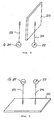
- Fig. 8 is an explanatory diagram showing a measuring method of the transmittance attenuation level.
- Fig. 9 is an explanatory diagram showing a measuring method of the coupling level.
- Hereinbelow, embodiments of the present invention will be described with reference to the drawings.
- Referring to Fig. 1, the shown embodiment shows a roll 1 formed by winding a tape 11 composed of only a thin film of a composite magnetic body formed by dispersing soft magnetic powder into an organic binding agent.
- As shown by 11, 11' in Fig. 4, a section of the tape 11 has a structure in which the soft magnetic powder (shown by dots) is dispersed into a layer of the organic binding agent (shown by hatching of oblique thick lines).
- As the foregoing soft magnetic powder, an Fe-Al-Si alloy or an Fe-Ni alloy having a large high frequency permeability can be cited.
- As the foregoing organic binding agent, thermoplastic resin, such as polyester resin, polyvinyl chloride resin, polyvinyl butyral resin, polyurethane resin, cellulose resin, nitrile-butadiene rubber or styrene-butadiene rubber, or a polymer thereof can be cited. Further, chlorinated polyethylene can also be used. Particularly, an elastomer having elasticity is suitable for tape.
- Referring to Fig. 2, the shown embodiment shows a
roll 2 formed by winding anadhesive tape 21 which is obtained by applying a thin layer 12 (in the figure, shown by hatching of horizontal lines) of an adhesive onto the surface of a tape 11 constituted of a thin film of a composite magnetic body formed by dispersing soft magnetic powder into an organic binding agent. - Referring to Fig. 3, the shown embodiment shows a
roll 3 formed by winding a self-welding tape 31 which is obtained by applying a thin layer 13 (in the figure, shown by hatching of mesh) of a self-welding agent onto the surface of a tape 11 constituted of a thin film of a composite magnetic body formed by dispersing soft magnetic powder into an organic binding agent. - Fig. 4 shows an example in which a thin film forming a tape has a stacked structure of layers of composite magnetic bodies and a metal layer. The shown example is an
adhesive tape 41 of a structure, wherein ametal layer 14 is interposed between tape layers 11 and 11' composed of composite magnetic bodies, and anadhesive layer 12 is provided on the surface of the tape layer 11 composed of the composite magnetic body. - As the metal layer, a metal foil, a net made of metal wires (metal mesh), an electroless plating layer, a deposited metal layer or the like may be used.
- On the other hand, a self-
welding agent layer 13 may be used instead of theadhesive layer 12 so as to form a self-welding tape. For showing this, (13) is added adjacent toreference sign 12 in the figure. Naturally, if not necessary, theadhesive layer 12 and the self-welding agent layer 13 both can be omitted. - One composite magnetic layer is acceptable. On the other hand, a plurality of composite magnetic layers and metal layers may be stacked.
- Table 1 shows an example of the composite magnetic body used in the embodiments shown in Figs. 1 to 4.
Table 1 Soft magnetic powder Fe-Al- Si alloy 80 weight parts Average particle diameter: 45 µm Aspect ratio: >5 Annealing: Ar atmosphere 650°C, 2 hours Organic binding agent (chlorinated polyethylene) 20 weight parts - The composite magnetic body was produced in the following manner. The soft magnetic powder obtained by a normal method was vapor-phase oxidized in an atmosphere of nitrogen-oxygen mixed gas at a 20% oxygen partial pressure, and oxide films were formed on the surfaces thereof. The powder and chlorinated polyethylene were heated and kneaded, and then formed under pressure to obtain a formed body of the composite magnetic body. The surface resistance of the composite magnetic body was measured and found to be 1 x 10⁶Ω.
- Fig. 5 shows a measured µ-f (permeability-frequency) characteristic of the foregoing composite magnetic body. Solid lines represent µ characteristics after annealing, while broken lines represent µ characteristics before annealing. As shown in Fig. 5, the composite magnetic body before annealing has peaks in µ" (complex permeability) which appear following the magnetic resonance, and it is observed that the magnetic resonance occurs at two points. After it is subjected to the annealing, it is seen that µ" reveals high values over a wide range, and µ" also reveals large values at high frequencies.
- Hereinbelow, examples of composite magnetic tapes according to the present invention will be described.
- Using the composite magnetic body shown in Table 1, as shown in Fig. 1, a tape 11 having a mean width of 15mm and a mean thickness of 0.3mm was formed.
- As shown in Fig. 4, the composite magnetic body of Table 1 was formed into two layers 11 and 11' and a nickel mesh was interposed therebetween as a
conductor layer 14, to form a multilayered structure so that a tape composed of athin belt 41 having a mean dimension of 15mm and a mean thickness of 0.3mm was formed. The nickel mesh of 100 meshes with t = 0.05mm was used. In this example, either theadhesive layer 12 or the self-welding layer (13) was used. - Using the composite magnetic body of Table 1, a tape 11 having a mean width of 15mm and a mean thickness of 0.3mm was formed. Then, as shown in Fig. 2, an adhesive 12 having electrically insulating and conductive properties was applied to the tape 11 to obtain an
adhesive tape 21. - As shown in Fig. 4, the composite magnetic body of Table 1 was formed into two layers 11 and 11' and a nickel mesh was interposed therebetween as a
conductor layer 14, to form a multilayered structure so that a tape composed of a thin belt having a mean width of 15mm and a mean thickness of 0.3mm was formed. Anadhesive layer 12 was applied to the surface of the tape to obtain anadhesive tape 41. The nickel mesh of 100 meshes with t = 0.05mm was used. - Using the composite magnetic body shown in Table 1, a tape 11 having a mean width of 15mm and a mean thickness of 0.3mm was formed. Then, as shown in Fig. 3, a self-welding
layer 13 made of epoxy resin as a main component was applied to the tape 11 to obtain a self-weldingtape 31. As the main component of the self-welding layer, polyamide resin, polyester resin or the like may be used other than the epoxy resin. - As shown in Fig. 4, the composite magnetic body of Table 1 was formed into two layers 11 and 11' and a nickel mesh was interposed therebetween as a
conductor layer 14, to form a multilayered structure so that a tape composed of a thin belt having a mean width of 15mm and a mean thickness of 0.3mm was formed. The foregoing self-weldingagent 13 was applied to the tape to obtain a self-weldingtape 41. The nickel mesh of 100 meshes with t = 0.05mm was used. - With respect to samples of the examples 1 to 6, transmittance attenuation levels and coupling levels were measured, respectively.
- As shown in Figs. 8 and 9, an apparatus having an electromagnetic wave generator G and an electromagnetic field strength measuring device (reception element) 22, which were connected to an electromagnetic field transmitting
micro-loop antenna 23 and an electromagnetic field receivingmicro-loop antenna 24 each having a loop diameter of not greater than 2mm, was used in the measurement. A spectrum analyzer, not shown, was connected to the electromagnetic fieldstrength measuring device 22, and the measurement was carried out using as a reference an electromagnetic field strength in the state where no sample was present. - In the measurement of the transmittance attenuation level, as shown in Fig. 8, a
sample 20 was disposed between the electromagnetic field transmittingmicro-loop antenna 23 and the electromagnetic field receivingmicro-loop antenna 24. - In the measurement of the coupling level, as shown in Fig. 9, the
sample 20 was disposed so that one side thereof confronts the electromagnetic field transmittingmicro-loop antenna 23 and the electromagnetic field receivingmicro-loop antenna 24. - The transmittance attenuation levels and the coupling levels measured by the foregoing method are shown in Figs. 6 and 7, respectively. In the figures, characteristics of the examples 1 to 6 are shown by ① to ⑥ and, as a comparative example, characteristics of a metal shield plate in the form of a copper plate with a thickness t = 0.035mm are shown by ⑤.
- As seen from Figs. 6 and 7, in the examples 1 to 6 according to the present invention, the transmittance attenuation levels and the coupling levels are both reduced. On the contrary, in the comparative example, it is seen that although the transmittance attenuation level is much reduced, the coupling level is increased. From the foregoing results, it is seen that the composite magnetic tape according to the present invention can effectively remove the radiant noise without inducing the secondary radiant noise due to reflection.
- According to the present invention, it is possible to provide a tape which can prevent high frequency radiation and reflection noise easily, like an insulating tape for electric insulation, without inducing secondary radiation, using a tape, an adhesive tape or a self-welding tape constituted of a composite magnetic body which can keep an electromagnetic absorption effect even at a high frequency band.
Claims (5)
- A composite magnetic tape, comprising a thin film of a composite magnetic body formed by dispersing soft magnetic powder into an organic binding agent, wherein said soft magnetic powder is powder being flat,
characterized in that said soft magnetic powder has oxide films on the surfaces thereof,
wherein the composite magnetic body has at least two magnetic resonance points in the µ" component of the complex permeability. - A composite magnetic tape as recited in claim 1, comprising conductor layer stacked on the thin film of the magnetic body. in the µ" component of the complex permeability.
- A composite magnetic tape as recited in claim 1 or 2, wherein a surface of the tape has an adhesive layer.
- A composite magnetic tape as recited in claim 1 or 2, wherein a surface of the tape has a layer of a self-welding agent.
- A composite magnetic tape as recited in any one of claims 1 to 4, wherein said organic binding agent is an elastomer.
Applications Claiming Priority (3)
| Application Number | Priority Date | Filing Date | Title |
|---|---|---|---|
| JP8248559A JPH1074613A (en) | 1996-08-30 | 1996-08-30 | Tape, adhesive tape and self-bonding tape |
| JP248559/96 | 1996-08-30 | ||
| PCT/JP1997/003045 WO1998009301A1 (en) | 1996-08-30 | 1997-09-01 | Composite magnetic tape |
Publications (3)
| Publication Number | Publication Date |
|---|---|
| EP0877394A1 EP0877394A1 (en) | 1998-11-11 |
| EP0877394A4 EP0877394A4 (en) | 2000-04-12 |
| EP0877394B1 true EP0877394B1 (en) | 2007-02-14 |
Family
ID=17179965
Family Applications (1)
| Application Number | Title | Priority Date | Filing Date |
|---|---|---|---|
| EP97937857A Expired - Lifetime EP0877394B1 (en) | 1996-08-30 | 1997-09-01 | Composite magnetic tape |
Country Status (8)
| Country | Link |
|---|---|
| US (1) | US6723914B1 (en) |
| EP (1) | EP0877394B1 (en) |
| JP (1) | JPH1074613A (en) |
| KR (1) | KR100486182B1 (en) |
| CN (1) | CN1143326C (en) |
| DE (1) | DE69737349T2 (en) |
| TW (1) | TW388153B (en) |
| WO (1) | WO1998009301A1 (en) |
Families Citing this family (19)
| Publication number | Priority date | Publication date | Assignee | Title |
|---|---|---|---|---|
| JP2001297905A (en) | 2000-04-17 | 2001-10-26 | Tokin Corp | High frequency current suppressor |
| US6576832B2 (en) * | 2001-03-07 | 2003-06-10 | Nokia Mobile Phones Ltd. | Electronic device molded cover having a releasable EMI shield |
| US6912135B1 (en) * | 2002-11-13 | 2005-06-28 | Ncr Corporation | Providing shields for systems |
| JP4106285B2 (en) * | 2003-02-12 | 2008-06-25 | アルプス電気株式会社 | High frequency equipment |
| US7167140B2 (en) | 2003-07-02 | 2007-01-23 | Nec Tokin Corporation | Coil antenna |
| JP3964401B2 (en) | 2004-04-27 | 2007-08-22 | Necトーキン株式会社 | Antenna core, coil antenna, watch, mobile phone, electronic device |
| EP1592085B1 (en) * | 2004-04-27 | 2008-07-16 | Nec Tokin Corporation | Coil Antenna |
| JP2006301900A (en) * | 2005-04-20 | 2006-11-02 | Dainippon Printing Co Ltd | Non-contact IC tag label |
| CN1873849B (en) * | 2005-06-01 | 2011-07-06 | 吴泓志 | Improved structure of soft magnet |
| US20070046408A1 (en) * | 2005-08-30 | 2007-03-01 | Youngtack Shim | Magnet-shunted systems and methods |
| JP2007299907A (en) * | 2006-04-28 | 2007-11-15 | Nitto Denko Corp | Structure having characteristics of conducting or absorbing electromagnetic waves |
| WO2009153682A1 (en) * | 2008-06-18 | 2009-12-23 | Koninklijke Philips Electronics, N.V. | Electrocardiograph for magnetic resonance imaging and electrode patch for same |
| DE102011076717A1 (en) * | 2011-05-30 | 2012-12-06 | Siemens Aktiengesellschaft | High-frequency antenna unit, a magnetic resonance apparatus having a high-frequency antenna unit, and a manufacturing method for a high-frequency antenna unit |
| KR101800105B1 (en) * | 2013-05-30 | 2017-11-21 | 가부시키가이샤 히다치 하이테크놀로지즈 | Charged particle beam device |
| JP6137402B2 (en) * | 2014-02-27 | 2017-05-31 | 日立金属株式会社 | Magnetic tape and shielded cable |
| CN105744818A (en) * | 2016-02-03 | 2016-07-06 | 中电海康集团有限公司 | Flexible magnetic shielding and anti-irradiation film |
| US12152177B2 (en) * | 2018-06-29 | 2024-11-26 | Berry Global, Inc. | Magnetic adhesive for use on skin |
| JP7200923B2 (en) * | 2019-12-25 | 2023-01-10 | 株式会社オートネットワーク技術研究所 | Telecommunication wire |
| CN111370211A (en) * | 2020-03-26 | 2020-07-03 | 睿集芯电气科技(苏州)有限公司 | A low-power chip transformer with electromagnetic shielding |
Family Cites Families (21)
| Publication number | Priority date | Publication date | Assignee | Title |
|---|---|---|---|---|
| JPS55120109A (en) * | 1979-03-12 | 1980-09-16 | Hitachi Metals Ltd | Magnetic tape for attraction |
| JPS59119708A (en) * | 1982-12-24 | 1984-07-11 | Hotsukou Denshi Kk | Shield type inductance element |
| JPS59201493A (en) * | 1983-04-29 | 1984-11-15 | ティーディーケイ株式会社 | Electromagnetic shielding material |
| JPS6268798A (en) * | 1985-09-20 | 1987-03-28 | 株式会社ブリヂストン | White board |
| JP2565859B2 (en) * | 1987-10-16 | 1996-12-18 | ティーディーケイ株式会社 | Soft magnetic powder for magnetic shield and magnetic shield material |
| JPH0715124B2 (en) * | 1988-12-05 | 1995-02-22 | 株式会社神戸製鋼所 | Method for producing magnetic composite material having excellent magnetic properties |
| JP2696771B2 (en) * | 1988-12-29 | 1998-01-14 | 株式会社リケン | Magnetic shield lattice |
| JPH02180610A (en) * | 1988-12-29 | 1990-07-13 | Riken Corp | Magnetic shield filter |
| JPH0359129A (en) * | 1989-07-25 | 1991-03-14 | Nakatsu Shiko Kk | Electromagnetic wave shielding material |
| US5260128A (en) * | 1989-12-11 | 1993-11-09 | Kabushiki Kaisha Riken | Electromagnetic shielding sheet |
| US5207841A (en) * | 1990-04-12 | 1993-05-04 | Tdk Corporation | Soft magnetic powder and magnetic shield composition |
| JPH05143959A (en) * | 1991-11-25 | 1993-06-11 | Dainippon Ink & Chem Inc | Recording medium for magnetic card |
| JPH05299232A (en) * | 1992-04-20 | 1993-11-12 | Matsushita Electric Ind Co Ltd | Resin molded magnetic material |
| JPH05325789A (en) * | 1992-05-14 | 1993-12-10 | Kanegafuchi Chem Ind Co Ltd | How to attach the magnetic field correction sheet for the deflection yoke |
| JPH06143468A (en) * | 1992-11-11 | 1994-05-24 | Kanegafuchi Chem Ind Co Ltd | Raw roll of ferrite sheet and method for processing ferrite sheet |
| JP2970297B2 (en) * | 1993-02-26 | 1999-11-02 | 三菱マテリアル株式会社 | High resistance magnetic shield material |
| JP3235034B2 (en) * | 1993-04-12 | 2001-12-04 | 三菱電機ホーム機器株式会社 | rice cooker |
| JP3401650B2 (en) * | 1994-01-20 | 2003-04-28 | エヌイーシートーキン株式会社 | Electromagnetic interference suppressor |
| JPH08509351A (en) | 1994-02-16 | 1996-10-01 | フィリップス エレクトロニクス ネムローゼ フェンノートシャップ | Method and apparatus for error-correctable data transmission based on semi-cyclic code |
| SE504155C2 (en) * | 1994-03-03 | 1996-11-25 | Tore Carl Fredrik Klason | Method for producing ferromagnetic fibers and EMI shielding materials containing the fibers |
| EP0854669B1 (en) * | 1997-01-20 | 2003-03-26 | Daido Steel Company Limited | Soft magnetic alloy powder for electromagnetic and magnetic shield, and shielding members containing the same |
-
1996
- 1996-08-30 JP JP8248559A patent/JPH1074613A/en active Pending
-
1997
- 1997-09-01 EP EP97937857A patent/EP0877394B1/en not_active Expired - Lifetime
- 1997-09-01 CN CNB971911495A patent/CN1143326C/en not_active Expired - Lifetime
- 1997-09-01 DE DE69737349T patent/DE69737349T2/en not_active Expired - Lifetime
- 1997-09-01 WO PCT/JP1997/003045 patent/WO1998009301A1/en not_active Ceased
- 1997-09-01 KR KR10-1998-0703108A patent/KR100486182B1/en not_active Expired - Lifetime
- 1997-09-05 TW TW086112819A patent/TW388153B/en not_active IP Right Cessation
-
2000
- 2000-02-23 US US09/598,487 patent/US6723914B1/en not_active Expired - Lifetime
Also Published As
| Publication number | Publication date |
|---|---|
| WO1998009301A1 (en) | 1998-03-05 |
| CN1143326C (en) | 2004-03-24 |
| JPH1074613A (en) | 1998-03-17 |
| KR19990067159A (en) | 1999-08-16 |
| CN1199496A (en) | 1998-11-18 |
| US6723914B1 (en) | 2004-04-20 |
| DE69737349T2 (en) | 2007-05-31 |
| EP0877394A1 (en) | 1998-11-11 |
| TW388153B (en) | 2000-04-21 |
| KR100486182B1 (en) | 2005-06-16 |
| EP0877394A4 (en) | 2000-04-12 |
| DE69737349D1 (en) | 2007-03-29 |
Similar Documents
| Publication | Publication Date | Title |
|---|---|---|
| US6723914B1 (en) | Composite magnetic tape | |
| EP0667643B1 (en) | Electromagnetic interference suppressing body having low electromagnetic transparency and reflection, and electronic equipment having the same | |
| US6416830B2 (en) | Composite magnetic tube and method of producing the same, and electromagnetic interference suppressing tube | |
| EP0785557B1 (en) | Composite magnetic material and product for eliminating electromagnetic interference | |
| US5260128A (en) | Electromagnetic shielding sheet | |
| EP1779713B1 (en) | Emi foil laminate gasket | |
| EP0764954B1 (en) | Composite magnetic article for electromagnetic interference suppressor | |
| US9832917B2 (en) | Electromagnetic wave absorbing sheet and method of manufacturing the same and electronic device using the same | |
| US6982378B2 (en) | Lossy coating for reducing electromagnetic emissions | |
| EP0859378B1 (en) | Emi preventive part and active device with the same | |
| EP0884739A1 (en) | Compound magnetic material and electromagnetic interference suppressor | |
| EP1511370B1 (en) | Counter emi component and counter emi method | |
| JP3712846B2 (en) | communication cable | |
| JPH1070808A (en) | Spiral tube | |
| JP3267194B2 (en) | Method of manufacturing electromagnetic wave shielding material, electromagnetic wave shielding material, and electromagnetic wave source using the shielding material | |
| JP3500596B2 (en) | How to fix the electromagnetic interference suppressor | |
| KR100517527B1 (en) | Thin sheet for electro-magnetic compatibility and heat radiation | |
| KR20260060672A (en) | Electromagnetic wave absorbing sheet, method for manufacturing electromagnetic wave absorbing sheet and cable comprising the electromagnetic wave absorbing sheet | |
| HK1001438B (en) | Composite magnetic material and product for eliminating electromagnetic interference | |
| KR20050092081A (en) | Counter emi component and counter emi method | |
| JPH09290588A (en) | PC card |
Legal Events
| Date | Code | Title | Description |
|---|---|---|---|
| PUAI | Public reference made under article 153(3) epc to a published international application that has entered the european phase |
Free format text: ORIGINAL CODE: 0009012 |
|
| 17P | Request for examination filed |
Effective date: 19980428 |
|
| AK | Designated contracting states |
Kind code of ref document: A1 Designated state(s): DE FR GB IT |
|
| A4 | Supplementary search report drawn up and despatched |
Effective date: 20000225 |
|
| AK | Designated contracting states |
Kind code of ref document: A4 Designated state(s): DE FR GB IT |
|
| RIC1 | Information provided on ipc code assigned before grant |
Free format text: 7H 01F 1/24 A, 7H 05K 9/00 B, 7H 01F 1/26 B |
|
| RAP1 | Party data changed (applicant data changed or rights of an application transferred) |
Owner name: NEC TOKIN CORPORATION |
|
| 17Q | First examination report despatched |
Effective date: 20030107 |
|
| GRAP | Despatch of communication of intention to grant a patent |
Free format text: ORIGINAL CODE: EPIDOSNIGR1 |
|
| GRAS | Grant fee paid |
Free format text: ORIGINAL CODE: EPIDOSNIGR3 |
|
| GRAA | (expected) grant |
Free format text: ORIGINAL CODE: 0009210 |
|
| AK | Designated contracting states |
Kind code of ref document: B1 Designated state(s): DE FR GB IT |
|
| REG | Reference to a national code |
Ref country code: GB Ref legal event code: FG4D |
|
| REF | Corresponds to: |
Ref document number: 69737349 Country of ref document: DE Date of ref document: 20070329 Kind code of ref document: P |
|
| ET | Fr: translation filed | ||
| PLBE | No opposition filed within time limit |
Free format text: ORIGINAL CODE: 0009261 |
|
| STAA | Information on the status of an ep patent application or granted ep patent |
Free format text: STATUS: NO OPPOSITION FILED WITHIN TIME LIMIT |
|
| 26N | No opposition filed |
Effective date: 20071115 |
|
| PGFP | Annual fee paid to national office [announced via postgrant information from national office to epo] |
Ref country code: GB Payment date: 20090826 Year of fee payment: 13 |
|
| PGFP | Annual fee paid to national office [announced via postgrant information from national office to epo] |
Ref country code: IT Payment date: 20090912 Year of fee payment: 13 |
|
| PGFP | Annual fee paid to national office [announced via postgrant information from national office to epo] |
Ref country code: FR Payment date: 20100921 Year of fee payment: 14 |
|
| PGFP | Annual fee paid to national office [announced via postgrant information from national office to epo] |
Ref country code: DE Payment date: 20100930 Year of fee payment: 14 |
|
| GBPC | Gb: european patent ceased through non-payment of renewal fee |
Effective date: 20100901 |
|
| PG25 | Lapsed in a contracting state [announced via postgrant information from national office to epo] |
Ref country code: IT Free format text: LAPSE BECAUSE OF NON-PAYMENT OF DUE FEES Effective date: 20100901 |
|
| PG25 | Lapsed in a contracting state [announced via postgrant information from national office to epo] |
Ref country code: GB Free format text: LAPSE BECAUSE OF NON-PAYMENT OF DUE FEES Effective date: 20100901 |
|
| REG | Reference to a national code |
Ref country code: FR Ref legal event code: ST Effective date: 20120531 |
|
| REG | Reference to a national code |
Ref country code: DE Ref legal event code: R119 Ref document number: 69737349 Country of ref document: DE Effective date: 20120403 |
|
| PG25 | Lapsed in a contracting state [announced via postgrant information from national office to epo] |
Ref country code: DE Free format text: LAPSE BECAUSE OF NON-PAYMENT OF DUE FEES Effective date: 20120403 |
|
| PG25 | Lapsed in a contracting state [announced via postgrant information from national office to epo] |
Ref country code: FR Free format text: LAPSE BECAUSE OF NON-PAYMENT OF DUE FEES Effective date: 20110930 |