EP0877333A2 - Vorrichtung zur drahtlosen Energieübertragung und Ausführung einer Aktion - Google Patents
Vorrichtung zur drahtlosen Energieübertragung und Ausführung einer Aktion Download PDFInfo
- Publication number
- EP0877333A2 EP0877333A2 EP98107287A EP98107287A EP0877333A2 EP 0877333 A2 EP0877333 A2 EP 0877333A2 EP 98107287 A EP98107287 A EP 98107287A EP 98107287 A EP98107287 A EP 98107287A EP 0877333 A2 EP0877333 A2 EP 0877333A2
- Authority
- EP
- European Patent Office
- Prior art keywords
- receiving device
- energy
- action
- actuator
- sensor
- Prior art date
- Legal status (The legal status is an assumption and is not a legal conclusion. Google has not performed a legal analysis and makes no representation as to the accuracy of the status listed.)
- Granted
Links
Images
Classifications
-
- G—PHYSICS
- G06—COMPUTING OR CALCULATING; COUNTING
- G06K—GRAPHICAL DATA READING; PRESENTATION OF DATA; RECORD CARRIERS; HANDLING RECORD CARRIERS
- G06K19/00—Record carriers for use with machines and with at least a part designed to carry digital markings
- G06K19/06—Record carriers for use with machines and with at least a part designed to carry digital markings characterised by the kind of the digital marking, e.g. shape, nature, code
- G06K19/067—Record carriers with conductive marks, printed circuits or semiconductor circuit elements, e.g. credit or identity cards also with resonating or responding marks without active components
- G06K19/07—Record carriers with conductive marks, printed circuits or semiconductor circuit elements, e.g. credit or identity cards also with resonating or responding marks without active components with integrated circuit chips
- G06K19/0701—Record carriers with conductive marks, printed circuits or semiconductor circuit elements, e.g. credit or identity cards also with resonating or responding marks without active components with integrated circuit chips at least one of the integrated circuit chips comprising an arrangement for power management
-
- G—PHYSICS
- G06—COMPUTING OR CALCULATING; COUNTING
- G06K—GRAPHICAL DATA READING; PRESENTATION OF DATA; RECORD CARRIERS; HANDLING RECORD CARRIERS
- G06K19/00—Record carriers for use with machines and with at least a part designed to carry digital markings
- G06K19/06—Record carriers for use with machines and with at least a part designed to carry digital markings characterised by the kind of the digital marking, e.g. shape, nature, code
- G06K19/067—Record carriers with conductive marks, printed circuits or semiconductor circuit elements, e.g. credit or identity cards also with resonating or responding marks without active components
- G06K19/07—Record carriers with conductive marks, printed circuits or semiconductor circuit elements, e.g. credit or identity cards also with resonating or responding marks without active components with integrated circuit chips
- G06K19/0723—Record carriers with conductive marks, printed circuits or semiconductor circuit elements, e.g. credit or identity cards also with resonating or responding marks without active components with integrated circuit chips the record carrier comprising an arrangement for non-contact communication, e.g. wireless communication circuits on transponder cards, non-contact smart cards or RFIDs
-
- G—PHYSICS
- G06—COMPUTING OR CALCULATING; COUNTING
- G06K—GRAPHICAL DATA READING; PRESENTATION OF DATA; RECORD CARRIERS; HANDLING RECORD CARRIERS
- G06K7/00—Methods or arrangements for sensing record carriers, e.g. for reading patterns
- G06K7/0008—General problems related to the reading of electronic memory record carriers, independent of its reading method, e.g. power transfer
-
- G—PHYSICS
- G07—CHECKING-DEVICES
- G07C—TIME OR ATTENDANCE REGISTERS; REGISTERING OR INDICATING THE WORKING OF MACHINES; GENERATING RANDOM NUMBERS; VOTING OR LOTTERY APPARATUS; ARRANGEMENTS, SYSTEMS OR APPARATUS FOR CHECKING NOT PROVIDED FOR ELSEWHERE
- G07C9/00—Individual registration on entry or exit
- G07C9/00174—Electronically operated locks; Circuits therefor; Nonmechanical keys therefor, e.g. passive or active electrical keys or other data carriers without mechanical keys
- G07C2009/00634—Power supply for the lock
Definitions
- the invention relates to a device for wireless energy transmission and execution of an action according to the generic term of claim 1.
- Devices for wireless energy transmission are considered Small household appliances and already known as power tools.
- a Charging station a voltage in a device-specific secondary coil induced to charge a device's own battery serves.
- the device is placed in the charging station for charging, so that the secondary coil in inductive coupling with the primary coil arrives and an energy transfer takes place can.
- Wireless energy and data transmission is also known from transponder systems, e.g. in the DE-PS 40 03 410 C2 are described.
- a base station can be coupled with one or more transponders.
- the Base station comprises at least one radio frequency transmitter, the can be energy transmitter and data transmitter at the same time and that Transponder includes a radio frequency receiver that works simultaneously Can be energy receiver and data receiver.
- the transponder can be equipped without its own energy source be because he is the one to operate his electronic circuit obtains the necessary energy from the base station. So far it is only known in transponder systems, a memory to describe or read out the transponder and any Execute commands or program commands on the circuit.
- transponder systems also have one Data transmission path in the reverse direction with a Transmitter or modulator in the transponder and a receiver in the base station.
- the base station with an actuator in the form of a lock or opener be equipped within the framework of an access control system is operated if one with an access authorization code equipped transponder in the field of the base station is introduced.
- Known base stations are included always equipped with its own energy source, which in is usually connected to the mains. There is also battery powered systems.
- remote control systems that consist of one Transmitter and a receiver exist, the receiving device is coupled to an actuator. With such systems only finds a data transmission to the receiving device instead of. In contrast, the receiving device is powered, any evaluation electronics and the actuator from one own battery or a rechargeable battery.
- the invention has for its object a device for wireless energy transmission and execution of an action to improve according to the preamble of claim 1 that the receiving device completely without its own Energy source.
- the triggering of the action can be remotely controlled from the sending device respectively.
- Next can trigger the action automatically by at least one sensor of the receiving device respectively.
- Other options are the Triggering the action after comparing one from the sending device transmitted codes with one in the receiving device stored code automatically by the receiving device to make.
- the triggering of the Action after authentication from between the transmitter and data exchanged with the receiving device. All of these variants cause, in addition to the event of Energy transfer itself one or more additional ones Criteria are checked before triggering the action so that increased security against manipulation attempts or a unwanted triggering are present.
- the action can also be triggered after selection and control of the assigned actuators.
- the receiving device can be a temporary energy store include that by energy transfer from the transmitter device is rechargeable to the receiving device and the energy supply the receiving device in transmission breaks or at Peaks in consumption.
- the sensor of the receiving device can be a frequency detector and / or a voltage value detector for that from the transmitting device radiated energy signal. Furthermore, the Sensor a time detector or a detector for an external be physical size and by means of a control unit Control actuator.
- the frequency detector Case be a selective resonant circuit that the actuator only triggers when the energy signal is at a certain Frequency is transmitted.
- the voltage value detector can open the level of a certain voltage must be set, either to a peak voltage from the transmitter to Signal transmitted to the receiving device or to a voltage, when charging a temporary energy storage occurs.
- An internal time base can also be used to trigger the action only when the energy signal is a predetermined time is pending.
- Detectors for external physical quantities enable more intelligent applications, such as the Control of an action depending on a temperature, one Pressure, a sound level, a brightness value, one Acceleration or similar quantities.
- the receiving device can be a logic or processor circuit for evaluating the sensor signal or the sensor signals include.
- Actions can then be carried out depending on each other control linked criteria and thereby the possibilities and improve security when triggering actions.
- the receiving device can be a logic or processor circuit for evaluating remote control signals from the transmitter device include.
- This measure can increase security against manipulation be improved when triggering remote-controlled actions.
- the receiving device may comprise a decoder, which at the request of the control unit of the receiving device from evaluates the authentication data sent to the sending device and if the authentication data is valid, the sensor and / or releases the actuator.
- This measure will result in an additional security check relocated to the receiving device. It is possible the possibility of controlling receiving devices individually restrict. This makes sense, for example, if multiple receiving devices are provided, and it differently entitled. Beneficiaries with a minor Authorization status can then only certain receiving devices remote control while beneficiaries with one higher entitlement status affect multiple receiving devices can.
- the receiving device can be a separate data transmitter and the transmitting device for a separate data receiver include bidirectional communication. Both in one store the transmitter device as well as in a memory of the Receiving device can store authentication data be. Both in the sending device and in the receiving device can be provided by means of decoders mutually transmitted authentication data on request can be checked for validity and only if they are valid both authentication data the sensor and / or the actuator can be released.
- authentication processes can be stored in a memory the transmitting device and / or the receiving device will.
- the energy transmission through the receiving device in be controllable in such a way that during an authentication at first only one of the energy required for data transmission the transmitting device is transmitted to the receiving device and only then to trigger an action required energy requested by the receiving device and transmitted from the transmitting device to the receiving device becomes.
- the first alternative is the time of authentication already for energy transmission to supply the actuator or sensor used. This allows the overall transmission time shorten and thus also the response time of the Improve sensor and / or actuator.
- the receiving device can separate temporary energy storage on the one hand for the actuator and on the other hand for the Sensor, the decoder and / or the logic or processor circuit and / or include the control unit.
- the separate version the energy storage has the advantage that circuits, that consume less energy, just a small energy store need and can go into operation faster because the necessary supply voltage is reached faster. Furthermore your operation will not be affected even if the Discharge the energy storage of the actuator by executing the action has been.
- the actuator is a lock or opener trained. You can possibly do this save a mechanical lock or security against failure of the lock due to environmental influences such as pollution or icing through the additional electronic controllable lock improve.
- the device for general Bridging an individually coded lock or opener to serve.
- Another use case are cash cassettes in which also get users individual keys when Financial institution, however, a master key for reasons of rationalization to be used, which here is an electrical Actuator performs a general locking function.
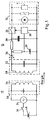
- Fig. 1 comprises a transmitter 10 for wireless
- a high frequency generator that acts as an energy transmitter 34 serves as well as a resonant circuit 50, the coil 54 also serves as an antenna.
- the transmission device 10 has its own energy source 48, which is by means of a control unit 20, which in the simplest case is a switch or Push button can be connected to the energy transmitter 34 can.
- One is adjacent to the transmission device 10
- Receiving device 12 the one tuned to the same frequency Includes resonant circuit 52, in which also the coil 58 serves as an antenna.
- the resonant circuit 52 of the receiving device 12 are an energy receiver 36 in the form of a Rectifier and temporary energy storage 38, 39 in the form connected by capacitors that have charging resistors are rechargeable.
- the one larger capacitor serves as an energy store 38 for an actuator 32 while the smaller capacitor as an energy store for an electronic circuit serves, which is shown here as sensor 30.
- This sensor 30 can be a voltage sensor with a comparator and Reference.
- the sensor 30 acts on the control input Control unit 26, which is a switching transistor or Tyristor includes, and an actuator 32 with the temporary energy storage 38 can connect.
- actuator 32 e.g. a Electromagnet, a motor or another transmitter are used. Due to the separate design of the energy store 38; 39 for the actuator 32 and for the sensor 30 the energy store 39 sized for a smaller capacity and therefore faster be rechargeable.
- the sensor 30 is thus ready for operation faster, as if he got his supply voltage from the same Energy storage 38 would relate to how the actuator 32. In addition is the operating voltage still present when Switching the actuator 32 on its energy store 38 completely is discharged.
- the higher capacity of the energy storage enables 38 for the actuator 32 that the switching current for one Electromagnets or the starting current applied to a motor can be, though, through wireless energy transmission such a peak performance would not be transferable.
- the energy transmitter 34 could also be a data code at the same time send out, which is evaluated by a decoder of the receiving device and compared with a stored code. The actuator is then only triggered if the code matches.
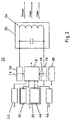
- Fig. 2 shows an expanded block diagram of a transmitter device.
- the transmission device 10 comprises a high-frequency generator, that both as an energy transmitter 34 and as a data transmitter 14 serves.
- a data receiver 16 is a Memory 20, a keyboard 44, a display 46, a control unit 18, an energy source 48 and one at the same time Transmitting and receiving resonant circuit 50 with a coil 54 provided as an antenna. Be 50 via the resonant circuit Transfer energy and data to the receiving device 12 and Receive data originating from the receiving device 12.
- the control unit 18 is also a decoder 40 for checking the validity of received Data assigned.
- the memory 20 is divided into one repeatedly writable area 64 and a non- or write-once area 60, in which an exclusive Ident number of the transmission device 10 is stored.
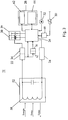
- Fig. 3 shows an expanded block diagram of a receiving device.
- the receiving device 12 has some similar Function blocks such as the transmission device described above 10. This is also the case with the receiving device 12 a data transmitter 24, a data receiver 22, a memory 28, a control unit 26 and a transmitter and receiver serving at the same time Oscillating circuit 52 present, its coil 58 as an antenna serves.
- Oscillating circuit 52 present, its coil 58 as an antenna serves.
- the data receiver 22 is an energy receiver 36 available. Via the resonant circuit 52 are from the transmitting device 10 energy and data received and Transfer data to the transmission device 10.
- the receiving device 12 comprises an actuator 32 and a sensor 30.
- the actuator 32 is controlled by the control unit 26 controlled. Control of the actuator 32 can be remotely controlled from the transmission device 10 or automatically by a Sensor 32 take place. For the evaluation of remote control signals serves a processor circuit assigned to the control unit 26 70. For automatic control by sensor signals the sensor 30 via a processor circuit 68 for evaluation of the sensor signal connected to the control unit 26.
- the wirelessly transmitted energy is stored in two energy stores 38 and 39.
- To supply energy to the Actuator 32 is used for energy storage 38 with high capacity and serves to supply energy to the other circuit parts the energy storage 39 because of its low capacity is quickly rechargeable and so is operational readiness the receiving device 12 quickly produces.
- the control of the data transmitter 24 and data receiver 22 as well of the memory 28 is carried out by the control unit 26. Furthermore the control unit 26 is a decoder 42 for checking the Validity of received data assigned.
- the memory 28 is divided into a repeatable area 66 and a non-writable or one-time writable area 62, in an exclusive identification number of the receiving device 12 is stored is.
- the transmission protocol used mastery can be done as follows.
- the transmitting device 10 and the receiving device 12 each other's authentication data through a test algorithm changed and retransmitted. Because the test algorithm both devices are known, the validity of the Authentication data can be checked without it being intercepted succeeds in decrypting the authentication data. The authentication data is updated with every new transmission changed.
- the test algorithm can be influenced by the identification numbers will. Only when the devices connected to each other have determined the validity of the identification data, the memory 28 as well as the actuator 32 and the sensor 30 released by the control unit 26 of the receiving device 12.
- Corresponding applications are also for doors and furniture safes, as used in hotels or with suitcases possible.
- the receiving device can be without its own Get along with the energy source. So you don't have to do that Power supply to be switched on, is still a regular exchange and maintenance of an otherwise usual battery is required.
- Another application is e.g. for one Tire pressure monitoring in the tire of a vehicle.
- an energy supply from the vehicle electrical system only under very complicated conditions possible.
- a temporary Energy storage can the receiving device over longer Determine the tire pressure via a sensor and activate it in the event of a drop in pressure, a data transmitter that makes an emergency call Vehicle electronics transmitted.
- a corresponding emergency call can also be discontinued just before the energy of the temporary Energy storage falls below a lower threshold and comes to an end. It can then be temporary from time to time Energy storage can be recharged.
Landscapes
- Engineering & Computer Science (AREA)
- Theoretical Computer Science (AREA)
- Computer Hardware Design (AREA)
- Microelectronics & Electronic Packaging (AREA)
- Physics & Mathematics (AREA)
- General Physics & Mathematics (AREA)
- Computer Networks & Wireless Communication (AREA)
- Artificial Intelligence (AREA)
- Computer Vision & Pattern Recognition (AREA)
- Lock And Its Accessories (AREA)
- Near-Field Transmission Systems (AREA)
- Mobile Radio Communication Systems (AREA)
- Arrangements For Transmission Of Measured Signals (AREA)
- Selective Calling Equipment (AREA)
Abstract
Description
- Fig. 1
- eine Prinzipschaltung einer Vorrichtung zur drahtlosen Energieübertragung mit einer Sendevorrichtung und einer Empfangesvorrichtung,
- Fig. 2
- ein erweitertes Blockschaltbild einer Sendervorrichtung und
- Fig. 3
- ein erweitertes Blockschaltbild einer Empfangsvorrichtung.
Claims (18)
- Vorrichtung zur drahtlosen Energieübertragung von einer Sendevorrichtung (10) zu einer Empfangsvorrichtung (12) und Ausführung wenigstens einer mechanischen und/oder elektrischen Aktion durch die Empfangsvorrichtung (12), dadurch gekennzeichnet, daß zur Energieversorgung des die mechanische und/oder elektrische Aktion ausführenden Aktors (32) die von der Sendevorrichtung zur Empfangsvorrichtung (12) übertragene Energie dient und daß die Auslösung der Aktion gesteuert erfolgt.
- Vorrichtung nach Anspruch 1, dadurch gekennzeichnet, daß die Auslösung der Aktion ferngesteuert von der Sendevorrichtung (10) erfolgt.
- Vorrichtung nach Anspruch 1, dadurch gekennzeichnet, daß die Auslösung der Aktion automatisch durch wenigstens einen Sensor (30) der Empfangsvorrichtung (12) erfolgt.
- Vorrichtung nach Anspruch 1, dadurch gekennzeichnet, daß die Auslösung der Aktion nach Vergleich eines von der Sendevorrichtung (10) übertragenen Kodes mit einem in der Empfangsvorrichtung (12) gespeicherten Kode automatisch durch die Empfangsvorrichtung (12) erfolgt.
- Vorrichtung nach Anspruch 1, dadurch gekennzeichnet, daß die Auslösung der Aktion nach Autentifikation von zwischen der Sendevorrichtung (10) und der Empfangsvorrichtung (12) ausgetauschten Daten erfolgt.
- Vorrichtung nach einem der Ansprüche 1 bis 5, dadurch gekennzeichnet, daß die Auslösung der Aktion nach Auswahl und Ansteuerung der zugeordneten Aktoren (32) erfolgt.
- Vorrichtung nach einem der Ansprüche 1 bis 6, dadurch gekennzeichnet, daß die Empfangsvorrichtung (12) wenigstens einen temporären Energiespeicher (38) umfaßt, der durch Energieübertragung von der Sendevorrichtung (10) zur Empfangsvorrichtung (12) aufladbar ist und die Energieversorgung der Empfangsvorrichtung (10) in Sendepausen oder bei Verbrauchsspitzen übernimmt.
- Vorrichtung nach nach einem der Ansprüche 1 bis 7, dadurch gekennzeichnet, daß der Sensor (30) der Empfangsvorrichtung (12) ein Frequenzdetektor und/oder ein Spannungswertdetektor für das von Sendevorrichtung (10) ausgestrahlte Energiesignal, ein Zeitdetektor oder ein Detektor für eine externe physikalische Größe ist und mittels einer Steuereinheit (26) den Aktor (32) steuert.
- Vorrichtung nach Anspruch 8, dadurch gekennzeichnet, daß die Empfangsvorrichtung (12) eine Logik- oder Prozessorschaltung (68) zur Auswertung des Sensorsignals oder der Sensorsignale umfaßt.
- Vorrichtung nach einem der Ansprüche 1 bis 9, dadurch gekennzeichnet, daß die Empfangsvorrichtung (12) eine Logik- oder Prozessorschaltung (70) zur Auswertung von Fernsteuersignalen des Senders umfaßt.
- Vorrichtung nach einem der Ansprüche 1 bis 10, dadurch gekennzeichnet, daß die Empfangsvorrichtung (12) einen Dekoder (49) umfaßt, welcher auf Anforderung der Steuereinheit (26) die Empfangsvorrichtung (12) von der Sendevorrichtung gesendete Autentifikationsdaten auswertet und bei Gültigkeit der Autentifikationsdaten den Sensor (30) und/oder den Aktor (32) freigibt.
- Vorrichtung nach einem der Ansprüche 1 bis 11, dadurch gekennzeichnet, daß die Empfangsvorrichtung (12) einen gesonderten Datensender (24) und die Sendevorrichtung (10) einen gesonderten Datenempfänger (16) zur bidirektionalen Kommunikation umfaßt, daß sowohl in einem Speicher (20) der Sendevorrichtung (10) als auch in einem Speicher (28) der Empfangsvorrichtung (12) Autentifikationsdaten abgelegt sind, daß sowohl in der Sendevorrichtung (10) als auch in der Empfangsvorrichtung (12) Dekoder (40; 42) vorgesehen sind, mittels der die auf Anforderung gegenseitig übermittelten Autentifikationsdaten auf Gültigkeit überprüfbar sind und erst bei Gültigkeit beider Autentifikationsdaten der Sensor (30) und/oder der Aktor (32) freigebbar sind.
- Vorrichtung nach Anspruch 11 oder 12, dadurch gekennzeichnet, daß Autentifikationsvorgänge in einem Speicher der Sendevorrichtung (10) und/oder der Empfangsvorrichtung (12) gespeichert werden.
- Vorrichtung nach einem der Ansprüche 11 bis 13, dadurch gekennzeichnet, daß die zur Energieversorgung des Sensors (30) und/oder Aktors (32) nötige Energie zeitgleich mit einer Datenübertragung zur Empfangsvorrichtung (12) oder einer bidirektionalen Datenkommunikation zwischen Sendevorrichtung (10) und Empfangsvorrichtung (12) übertragen wird oder daß die Energieübertragung durch die Empfangsvorrichtung (12) in der Weise steuerbar ist, daß während einer Autentifikation zuerst nur eine für die Datenübertragung nötige Energie von der Sendevorrichtung (10) zur Empfangsvorrichtung (12) übertragen wird und erst anschließend zur Auslösung einer Aktion die hierfür nötige Energie von der Empfangsvorrichtung (12) angefordert und von der Sendevorrichtung (10) zur Empfangsvorrichtung (12) übertragen wird.
- Vorrichtung nach einem der Ansprüche 1 bis 14, dadurch gekennzeichnet, daß die Empfangsvorrichtung (12) gesonderte temporäre Energiespeicher (38, 39) einerseits für den Aktor (32) und andererseits für den Sensor (30), den Dekoder (40) und/oder die Logik- oder Prozessorschaltung (64, 66) und/oder die Steuereinheit (26) umfaßt.
- Vorrichtung nach einem der Ansprüche 1 bis 15, dadurch gekennzeichnet, daß der Aktor (32) als Schloß oder Öffner ausgebildet ist.
- Verwendung einer Vorrichtung mit den Merkmalen des Anspruchs 16, dadurch gekennzeichnet, daß sie zur Betätigung des Schlosses oder Öffners der Tür eines Fahrzeugs, Grundstückes, Gebäudes, Warenkontainers oder dem Deckel einer Wertkassette, eines Wertstoff- oder Abfallsammelbahälters dient.
- Verwendung nach Anspruch 17, dadurch gekennzeichnet, daß die Vorrichtung zur Ausführung einer Generalschließfunktion bei einem individuell kodierten Schloß oder einem Öffner dient.
Priority Applications (1)
| Application Number | Priority Date | Filing Date | Title |
|---|---|---|---|
| US09/075,035 US6275143B1 (en) | 1997-05-09 | 1998-05-08 | Security device having wireless energy transmission |
Applications Claiming Priority (2)
| Application Number | Priority Date | Filing Date | Title |
|---|---|---|---|
| DE19719562A DE19719562A1 (de) | 1997-05-09 | 1997-05-09 | Drahtloses Datenübertragungssystem |
| DE19719562 | 1997-05-09 |
Publications (3)
| Publication Number | Publication Date |
|---|---|
| EP0877333A2 true EP0877333A2 (de) | 1998-11-11 |
| EP0877333A3 EP0877333A3 (de) | 2002-01-16 |
| EP0877333B1 EP0877333B1 (de) | 2004-11-10 |
Family
ID=29265469
Family Applications (2)
| Application Number | Title | Priority Date | Filing Date |
|---|---|---|---|
| EP98107287A Expired - Lifetime EP0877333B1 (de) | 1997-05-09 | 1998-04-22 | Vorrichtung zur drahtlosen Energieübertragung und Ausführung einer Aktion |
| EP98107483A Expired - Lifetime EP0877331B1 (de) | 1997-05-09 | 1998-04-24 | Drahtloses Datenübertragungssystem |
Family Applications After (1)
| Application Number | Title | Priority Date | Filing Date |
|---|---|---|---|
| EP98107483A Expired - Lifetime EP0877331B1 (de) | 1997-05-09 | 1998-04-24 | Drahtloses Datenübertragungssystem |
Country Status (2)
| Country | Link |
|---|---|
| EP (2) | EP0877333B1 (de) |
| DE (3) | DE19719562A1 (de) |
Cited By (4)
| Publication number | Priority date | Publication date | Assignee | Title |
|---|---|---|---|---|
| DE10348569A1 (de) * | 2003-10-20 | 2005-05-25 | Giesecke & Devrient Gmbh | Vorrichtung zum Ansteuern eines Aktuators |
| DE102005036290B4 (de) * | 2005-08-02 | 2009-04-30 | Gebrüder Frei GmbH & Co. KG | Bedienungssystem |
| DE102014219088A1 (de) * | 2014-09-22 | 2016-03-24 | Siemens Aktiengesellschaft | Anordnung sowie ein Verfahren zum Schalten einer Schaltstrecke mittels eines Schaltgerätes |
| DE102014219089A1 (de) * | 2014-09-22 | 2016-03-24 | Siemens Aktiengesellschaft | Anordnung und Verfahren zum Schalten von Schaltstrecken mittels Schaltgeräten |
Families Citing this family (10)
| Publication number | Priority date | Publication date | Assignee | Title |
|---|---|---|---|---|
| EP1018692B1 (de) | 1999-01-08 | 2006-06-28 | Anatoli Stobbe | Sicherungssystem, Transponder und Empfangsvorrichtung |
| DE10019539A1 (de) * | 2000-04-20 | 2001-10-25 | Abb Research Ltd | Sensor mit drahtloser Energieversorgung |
| DE10233597A1 (de) * | 2002-07-24 | 2004-02-05 | Brühn, Xenia | Optoakustische Signalgebung vom elektronischen Ausweis oder Transponder als Methode zur Warnung vor illegalen Zugriffsversuchen auf schlüssellos arbeitende Zugangssysteme |
| GB0403214D0 (en) * | 2004-02-13 | 2004-03-17 | Melexis Nv | Locking device |
| US20070131005A1 (en) * | 2005-12-14 | 2007-06-14 | Checkpoint Systems, Inc. | Systems and methods for providing universal security for items |
| CH701169B1 (de) | 2006-10-09 | 2010-12-15 | Legic Identsystems Ag | Vorrichtung zum Betrieb eines Schreib-/Lesegeräts. |
| EP2051189A1 (de) * | 2007-10-18 | 2009-04-22 | Siemens Aktiengesellschaft | Vorrichtung zur elektronischen Identifikation von Artikeln |
| FR2945162A1 (fr) | 2009-04-30 | 2010-11-05 | Pascal Metivier | Systeme d'alimentation externe d'une serrure comportant des moyens de communication sans contact de type nfc |
| DE102009043571B3 (de) * | 2009-09-30 | 2011-02-17 | Festo Ag & Co. Kg | Fluidisch-elektrische Einrichtung mit drahtloser Energiespeisung |
| DE102012102007A1 (de) | 2012-03-09 | 2013-09-12 | Infineon Technologies Ag | Leistungsversorgungsvorrichtung zum Liefern einer Spannung aus einem elektromagnetischen Feld |
Family Cites Families (6)
| Publication number | Priority date | Publication date | Assignee | Title |
|---|---|---|---|---|
| JPS60119873A (ja) * | 1983-11-29 | 1985-06-27 | 日産自動車株式会社 | 車両用施錠制御装置 |
| US4829296A (en) * | 1986-04-30 | 1989-05-09 | Carey S. Clark | Electronic lock system |
| DE4003410A1 (de) * | 1990-02-05 | 1991-08-08 | Anatoli Stobbe | Tragbares feldprogrammierbares detektierplaettchen |
| US5300875A (en) * | 1992-06-08 | 1994-04-05 | Micron Technology, Inc. | Passive (non-contact) recharging of secondary battery cell(s) powering RFID transponder tags |
| DE4323530A1 (de) * | 1993-07-14 | 1995-01-19 | Philips Patentverwaltung | Datenaustauschanordnung |
| JPH10307898A (ja) * | 1997-05-09 | 1998-11-17 | Toppan Printing Co Ltd | 充電式非接触icカードシステム |
-
1997
- 1997-05-09 DE DE19719562A patent/DE19719562A1/de not_active Withdrawn
-
1998
- 1998-04-22 EP EP98107287A patent/EP0877333B1/de not_active Expired - Lifetime
- 1998-04-22 DE DE59812235T patent/DE59812235D1/de not_active Expired - Lifetime
- 1998-04-24 EP EP98107483A patent/EP0877331B1/de not_active Expired - Lifetime
- 1998-04-24 DE DE59809318T patent/DE59809318D1/de not_active Expired - Lifetime
Cited By (4)
| Publication number | Priority date | Publication date | Assignee | Title |
|---|---|---|---|---|
| DE10348569A1 (de) * | 2003-10-20 | 2005-05-25 | Giesecke & Devrient Gmbh | Vorrichtung zum Ansteuern eines Aktuators |
| DE102005036290B4 (de) * | 2005-08-02 | 2009-04-30 | Gebrüder Frei GmbH & Co. KG | Bedienungssystem |
| DE102014219088A1 (de) * | 2014-09-22 | 2016-03-24 | Siemens Aktiengesellschaft | Anordnung sowie ein Verfahren zum Schalten einer Schaltstrecke mittels eines Schaltgerätes |
| DE102014219089A1 (de) * | 2014-09-22 | 2016-03-24 | Siemens Aktiengesellschaft | Anordnung und Verfahren zum Schalten von Schaltstrecken mittels Schaltgeräten |
Also Published As
| Publication number | Publication date |
|---|---|
| EP0877333A3 (de) | 2002-01-16 |
| DE59812235D1 (de) | 2004-12-16 |
| DE19719562A1 (de) | 1998-11-19 |
| EP0877331A3 (de) | 1999-10-20 |
| EP0877333B1 (de) | 2004-11-10 |
| DE59809318D1 (de) | 2003-09-25 |
| EP0877331A2 (de) | 1998-11-11 |
| EP0877331B1 (de) | 2003-08-20 |
Similar Documents
| Publication | Publication Date | Title |
|---|---|---|
| DE60121081T2 (de) | Sicherheitssystem zum Ermöglichen eines authentifizierten Zugangs einer Person zu einem gesichertem Raum | |
| EP2733681B1 (de) | Schließeinheit, Schließvorrichtung und Verfahren zum Entriegeln und/oder Verriegeln eines Schlosses | |
| EP1949345B1 (de) | Elektrohandwerkzeuggerät und akkupack hierfür | |
| DE10044723C1 (de) | Schließvorrichtung für eine Tür | |
| DE19603320C2 (de) | Elektronisch programmierbares Schließsystem mit Schloß und Schlüssel | |
| DE19738938B4 (de) | Schloß | |
| EP0877333B1 (de) | Vorrichtung zur drahtlosen Energieübertragung und Ausführung einer Aktion | |
| DE4329697A1 (de) | Fernsteuerbare Zugangskontrolleinrichtung | |
| EP0958161A1 (de) | Codesignalgeber, insbesondere für ein diebstahlschutzsystem eines kraftfahrzeugs | |
| EP1302374B1 (de) | Verfahren zum Initialisieren eines Zugangskontrollsystems mit mehreren elektronischen Schlüsseln und mehreren Objekten | |
| EP0602544B1 (de) | Fernsteuereinrichtung | |
| EP2304694A1 (de) | Verfahren zum betreiben eines schliesssystems | |
| EP3704675A1 (de) | Notbetätigungsvorrichtung für ein bewegliches teil eines fahrzeugs | |
| EP3479362B1 (de) | Schliessanordnung für einen schaltschrank und ein entsprechendes verfahren | |
| EP0659963A1 (de) | Elektronische Wegfahrsperre für ein Kraftfahrzeug | |
| EP3671664B1 (de) | System zum betreiben eines müllcontainers und verfahren zum betreiben eines müllcontainers | |
| EP1564689A2 (de) | Vorrichtung zum Betätigen eines Schlosses mit einer Not-Einrichtung zum Entsichern und/oder Sichern des Schlosses | |
| DE4433499C2 (de) | Elektronisches Diebstahlschutzsystem für ein Kraftfahrzeug | |
| DE4330118C1 (de) | Fernsteuerbare Zugangskontrolleinrichtung, insbesondere für ein Kraftfahrzeug | |
| EP0287686B2 (de) | Überwachte Schliessvorrichtung | |
| EP3027827B1 (de) | Elektromagnetisch sperrbarer fenstergriff | |
| EP1533450B1 (de) | Kraftfahrzeugschliesssystem | |
| EP2125451B1 (de) | Mobiler identifikationsgeber eines sicherheitssystemes | |
| EP3582192A1 (de) | Verfahren zur regelung eines zugangsregimes zu einem objekt, schliesseinheit und schliesssystem | |
| EP4264578A2 (de) | Elektronische schlossvorrichtung, insbesondere eines schlüsseltresors, und verfahren zum betreiben der elektrischen schlossvorrichtung |
Legal Events
| Date | Code | Title | Description |
|---|---|---|---|
| PUAI | Public reference made under article 153(3) epc to a published international application that has entered the european phase |
Free format text: ORIGINAL CODE: 0009012 |
|
| AK | Designated contracting states |
Kind code of ref document: A2 Designated state(s): AT BE CH CY DE DK ES FI FR GB GR IE IT LI LU MC NL PT SE Kind code of ref document: A2 Designated state(s): DE FR GB |
|
| AX | Request for extension of the european patent |
Free format text: AL;LT;LV;MK;RO;SI |
|
| PUAL | Search report despatched |
Free format text: ORIGINAL CODE: 0009013 |
|
| AK | Designated contracting states |
Kind code of ref document: A3 Designated state(s): AT BE CH CY DE DK ES FI FR GB GR IE IT LI LU MC NL PT SE |
|
| AX | Request for extension of the european patent |
Free format text: AL;LT;LV;MK;RO;SI |
|
| RIC1 | Information provided on ipc code assigned before grant |
Free format text: 7G 06K 7/00 A, 7G 06K 19/07 B, 7G 06K 7/08 B |
|
| 17P | Request for examination filed |
Effective date: 20020306 |
|
| AKX | Designation fees paid |
Free format text: DE FR GB |
|
| 17Q | First examination report despatched |
Effective date: 20030411 |
|
| GRAP | Despatch of communication of intention to grant a patent |
Free format text: ORIGINAL CODE: EPIDOSNIGR1 |
|
| GRAS | Grant fee paid |
Free format text: ORIGINAL CODE: EPIDOSNIGR3 |
|
| GRAA | (expected) grant |
Free format text: ORIGINAL CODE: 0009210 |
|
| AK | Designated contracting states |
Kind code of ref document: B1 Designated state(s): DE FR GB |
|
| REG | Reference to a national code |
Ref country code: GB Ref legal event code: FG4D Free format text: NOT ENGLISH |
|
| REG | Reference to a national code |
Ref country code: IE Ref legal event code: FG4D Free format text: GERMAN |
|
| REF | Corresponds to: |
Ref document number: 59812235 Country of ref document: DE Date of ref document: 20041216 Kind code of ref document: P |
|
| GBT | Gb: translation of ep patent filed (gb section 77(6)(a)/1977) |
Effective date: 20050118 |
|
| REG | Reference to a national code |
Ref country code: IE Ref legal event code: FD4D |
|
| PLBE | No opposition filed within time limit |
Free format text: ORIGINAL CODE: 0009261 |
|
| STAA | Information on the status of an ep patent application or granted ep patent |
Free format text: STATUS: NO OPPOSITION FILED WITHIN TIME LIMIT |
|
| ET | Fr: translation filed | ||
| 26N | No opposition filed |
Effective date: 20050811 |
|
| PGFP | Annual fee paid to national office [announced via postgrant information from national office to epo] |
Ref country code: DE Payment date: 20120413 Year of fee payment: 15 |
|
| PGFP | Annual fee paid to national office [announced via postgrant information from national office to epo] |
Ref country code: FR Payment date: 20120511 Year of fee payment: 15 Ref country code: GB Payment date: 20120423 Year of fee payment: 15 |
|
| GBPC | Gb: european patent ceased through non-payment of renewal fee |
Effective date: 20130422 |
|
| PG25 | Lapsed in a contracting state [announced via postgrant information from national office to epo] |
Ref country code: DE Free format text: LAPSE BECAUSE OF NON-PAYMENT OF DUE FEES Effective date: 20131101 Ref country code: GB Free format text: LAPSE BECAUSE OF NON-PAYMENT OF DUE FEES Effective date: 20130422 |
|
| REG | Reference to a national code |
Ref country code: FR Ref legal event code: ST Effective date: 20131231 |
|
| REG | Reference to a national code |
Ref country code: DE Ref legal event code: R119 Ref document number: 59812235 Country of ref document: DE Effective date: 20131101 |
|
| PG25 | Lapsed in a contracting state [announced via postgrant information from national office to epo] |
Ref country code: FR Free format text: LAPSE BECAUSE OF NON-PAYMENT OF DUE FEES Effective date: 20130430 |