EP0877221B2 - Heat exchanger constructed by a plurality of tubes - Google Patents
Heat exchanger constructed by a plurality of tubes Download PDFInfo
- Publication number
- EP0877221B2 EP0877221B2 EP98108350A EP98108350A EP0877221B2 EP 0877221 B2 EP0877221 B2 EP 0877221B2 EP 98108350 A EP98108350 A EP 98108350A EP 98108350 A EP98108350 A EP 98108350A EP 0877221 B2 EP0877221 B2 EP 0877221B2
- Authority
- EP
- European Patent Office
- Prior art keywords
- wall surface
- cap
- tank portion
- inside wall
- tank
- Prior art date
- Legal status (The legal status is an assumption and is not a legal conclusion. Google has not performed a legal analysis and makes no representation as to the accuracy of the status listed.)
- Expired - Lifetime
Links
Images


Classifications
-
- F—MECHANICAL ENGINEERING; LIGHTING; HEATING; WEAPONS; BLASTING
- F28—HEAT EXCHANGE IN GENERAL
- F28D—HEAT-EXCHANGE APPARATUS, NOT PROVIDED FOR IN ANOTHER SUBCLASS, IN WHICH THE HEAT-EXCHANGE MEDIA DO NOT COME INTO DIRECT CONTACT
- F28D1/00—Heat-exchange apparatus having stationary conduit assemblies for one heat-exchange medium only, the media being in contact with different sides of the conduit wall, in which the other heat-exchange medium is a large body of fluid, e.g. domestic or motor car radiators
- F28D1/02—Heat-exchange apparatus having stationary conduit assemblies for one heat-exchange medium only, the media being in contact with different sides of the conduit wall, in which the other heat-exchange medium is a large body of fluid, e.g. domestic or motor car radiators with heat-exchange conduits immersed in the body of fluid
- F28D1/04—Heat-exchange apparatus having stationary conduit assemblies for one heat-exchange medium only, the media being in contact with different sides of the conduit wall, in which the other heat-exchange medium is a large body of fluid, e.g. domestic or motor car radiators with heat-exchange conduits immersed in the body of fluid with tubular conduits
- F28D1/053—Heat-exchange apparatus having stationary conduit assemblies for one heat-exchange medium only, the media being in contact with different sides of the conduit wall, in which the other heat-exchange medium is a large body of fluid, e.g. domestic or motor car radiators with heat-exchange conduits immersed in the body of fluid with tubular conduits the conduits being straight
- F28D1/0535—Heat-exchange apparatus having stationary conduit assemblies for one heat-exchange medium only, the media being in contact with different sides of the conduit wall, in which the other heat-exchange medium is a large body of fluid, e.g. domestic or motor car radiators with heat-exchange conduits immersed in the body of fluid with tubular conduits the conduits being straight the conduits having a non-circular cross-section
- F28D1/05366—Assemblies of conduits connected to common headers, e.g. core type radiators
- F28D1/05391—Assemblies of conduits connected to common headers, e.g. core type radiators with multiple rows of conduits or with multi-channel conduits combined with a particular flow pattern, e.g. multi-row multi-stage radiators
-
- F—MECHANICAL ENGINEERING; LIGHTING; HEATING; WEAPONS; BLASTING
- F28—HEAT EXCHANGE IN GENERAL
- F28F—DETAILS OF HEAT-EXCHANGE AND HEAT-TRANSFER APPARATUS, OF GENERAL APPLICATION
- F28F9/00—Casings; Header boxes; Auxiliary supports for elements; Auxiliary members within casings
- F28F9/02—Header boxes; End plates
- F28F9/0202—Header boxes having their inner space divided by partitions
- F28F9/0204—Header boxes having their inner space divided by partitions for elongated header box, e.g. with transversal and longitudinal partitions
- F28F9/0209—Header boxes having their inner space divided by partitions for elongated header box, e.g. with transversal and longitudinal partitions having only transversal partitions
- F28F9/0212—Header boxes having their inner space divided by partitions for elongated header box, e.g. with transversal and longitudinal partitions having only transversal partitions the partitions being separate elements attached to header boxes
-
- F—MECHANICAL ENGINEERING; LIGHTING; HEATING; WEAPONS; BLASTING
- F28—HEAT EXCHANGE IN GENERAL
- F28F—DETAILS OF HEAT-EXCHANGE AND HEAT-TRANSFER APPARATUS, OF GENERAL APPLICATION
- F28F9/00—Casings; Header boxes; Auxiliary supports for elements; Auxiliary members within casings
- F28F9/02—Header boxes; End plates
- F28F9/0243—Header boxes having a circular cross-section
-
- F—MECHANICAL ENGINEERING; LIGHTING; HEATING; WEAPONS; BLASTING
- F28—HEAT EXCHANGE IN GENERAL
- F28D—HEAT-EXCHANGE APPARATUS, NOT PROVIDED FOR IN ANOTHER SUBCLASS, IN WHICH THE HEAT-EXCHANGE MEDIA DO NOT COME INTO DIRECT CONTACT
- F28D21/00—Heat-exchange apparatus not covered by any of the groups F28D1/00 - F28D20/00
- F28D2021/0019—Other heat exchangers for particular applications; Heat exchange systems not otherwise provided for
- F28D2021/0068—Other heat exchangers for particular applications; Heat exchange systems not otherwise provided for for refrigerant cycles
- F28D2021/0073—Gas coolers
-
- F—MECHANICAL ENGINEERING; LIGHTING; HEATING; WEAPONS; BLASTING
- F28—HEAT EXCHANGE IN GENERAL
- F28F—DETAILS OF HEAT-EXCHANGE AND HEAT-TRANSFER APPARATUS, OF GENERAL APPLICATION
- F28F2220/00—Closure means, e.g. end caps on header boxes or plugs on conduits
-
- Y—GENERAL TAGGING OF NEW TECHNOLOGICAL DEVELOPMENTS; GENERAL TAGGING OF CROSS-SECTIONAL TECHNOLOGIES SPANNING OVER SEVERAL SECTIONS OF THE IPC; TECHNICAL SUBJECTS COVERED BY FORMER USPC CROSS-REFERENCE ART COLLECTIONS [XRACs] AND DIGESTS
- Y10—TECHNICAL SUBJECTS COVERED BY FORMER USPC
- Y10S—TECHNICAL SUBJECTS COVERED BY FORMER USPC CROSS-REFERENCE ART COLLECTIONS [XRACs] AND DIGESTS
- Y10S165/00—Heat exchange
- Y10S165/454—Heat exchange having side-by-side conduits structure or conduit section
- Y10S165/471—Plural parallel conduits joined by manifold
- Y10S165/488—Header is rounded in cross section, e.g. circular, oval
-
- Y—GENERAL TAGGING OF NEW TECHNOLOGICAL DEVELOPMENTS; GENERAL TAGGING OF CROSS-SECTIONAL TECHNOLOGIES SPANNING OVER SEVERAL SECTIONS OF THE IPC; TECHNICAL SUBJECTS COVERED BY FORMER USPC CROSS-REFERENCE ART COLLECTIONS [XRACs] AND DIGESTS
- Y10—TECHNICAL SUBJECTS COVERED BY FORMER USPC
- Y10T—TECHNICAL SUBJECTS COVERED BY FORMER US CLASSIFICATION
- Y10T29/00—Metal working
- Y10T29/49—Method of mechanical manufacture
- Y10T29/4935—Heat exchanger or boiler making
- Y10T29/49389—Header or manifold making
Definitions
- the present invention relates to a heat exchanger according to the preamble of claim 1.
- Such a heat exchanger is disclosed by US-A-5481800.
- This known heat exchanger comprises a cap covering an end portion of a columnar tank, which cap has a spherical inside surface protruding inwardly toward the inside space of the tank.
- the cap is connected to the tank such that the inside surface of the cap and the inside surface of the tank are arranged in perpendicular relation.
- JP-B-7-18602 discloses a vapor compression type refrigerating cycle (CO 2 -refrigerating cycle) where carbon dioxide (CO 2 ) is used as a refrigerant in place of freon.
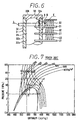
- the CO 2 -refrigerating cycle operates in the same manner as the conventional vapor compression type refrigerating cycle does where the freon is used as a refrigerant. That is, as denoted by A-B-C-D-A in FIG. 7 (Mollier chart of the CO 2 -refrigerating cycle), gas-phase CO 2 is compressed (A-B) by a compressor to high-temperature and high-pressure super-critical phase CO 2 , and the super-critical phase CO 2 is cooled (B-C) by a heat emitter (gas cooler).
- the super-critical phase CO 2 is pressure-reduced (C-D) by a pressure reducer to a gas-liquid phase CO 2 , and the gas-liquid phase CO 2 is evaporated (D-A) by an evaporator while cooling an outside fluid by absorbing heat from the outside fluid.
- the CO 2 changes from super-critical phase to gas-liquid phase when the pressure thereof becomes to be under a saturated liquid pressure (pressure at a cross point between a segment CD and a saturated liquid line in FIG. 7).
- a saturated liquid pressure pressure at a cross point between a segment CD and a saturated liquid line in FIG. 7.
- the CO 2 changes from a condition (C) to a condition (D) slowly, the CO 2 changes from the super-critical phase to the gas-liquid phase via liquid phase.
- the molecule of CO 2 moves as in the gas phase while the density of CO 2 is substantially the same as the liquid-density thereof.
- the critical temperature of CO 2 is about 31 °C, which is lower than that of freon (for example, the critical temperature of R12 is 112 °C).
- freon for example, the critical temperature of R12 is 112 °C.
- the condition (C) of CO 2 at the outlet side of the heat emitter depends on the pressure of CO 2 discharged by the compressor and the temperature of CO 2 at the outlet side of the heat emitter. As the outside air temperature cannot be controlled, the CO 2 temperature at the outlet side of the heat emitter cannot be controlled.
- condition (C) can be controlled by only controlling a discharge pressure in the compressor (CO 2 pressure at the outlet side of the heat emitter). That is, when the outside air temperature is high in summer or the like, the CO 2 pressure at the outlet side of the heat emitter needs to be raised as denoted by E-F-G-H-E in FIG. 7, for attaining a sufficient cooling performance (enthalpy difference).
- the maximum CO 2 pressure in the CO 2 -refrigerating cycle is about ten times as high as that in the conventional refrigerating cycle where the freon is used as refrigerant.
- JP-U-63-54979 discloses a heat exchanger in which the end portion of a header tank is formed into a semi-sphere shape. The strength of the end portion of this header tank is high.
- this heat exchanger is formed by stacking plural thin plates of a predetermined shape, and by brazing them together. Thus, as this heat exchanger has many connecting portions, and the pressure strength thereof is not sufficient in view of entire heat exchanger.
- An object of the present invention is to provide a heating heat exchanger, in which each connecting portion is brazed firmly for attaining a high pressure-strength.
- a first connecting portion (cap-gap) between a cap and a tank portion is separated awayfrom a second connecting portion (tube-gap) between the tank portion and a tube by a predetermined distance.
- the brazing material is suctioned into both connecting portions (both gaps) sufficiently, and both connecting portions are brazed firmly.
- the high pressure-strength is attained in the entire heat exchanger.
- a columnar like-inside space is formed in a tank portion, and an inside wall surface of the cap includes a spherical surface. That is, the inside wall surface of the cap is connected tangentially and smoothly (without a sharp corner) to the inside wall surface of the tank portion.
- a stress concentration is reduced at the connecting portion, thereby increasing the pressure-strength of a headertank formed by the cap and the tank portion.
- an outer shape of the header tank is formed into a columnar shape both ends of which are flat covered. Therefore, the thickness of the end corner portion of the header tank is large, thereby increasing the strength of the header tank to an outer force acting the cap from the outside.
- a heat exchanger according to the present invention is applied to a heat emitter 1 in a refrigerating cycle where carbon dioxide (CO 2 ) is used as a refrigerant to provide a CO 2 -refrigerating cycle.
- CO 2 carbon dioxide
- the heat emitter 1 includes a core portion 2 carrying out heat exchange between the refrigerant (CO 2 ) and air.
- the core portion 2 includes a plurality of tubes 21 made of aluminum (A1100) through which the refrigerant flows, and a plurality of cooling fins 22 disposed between the adjacent tubes 21.
- the cooling fin 22 is made of aluminum (A3003) and formed into a corrugate shape.
- the tubes 21 and the cooling fins 22 are brazed integrally by Al-Si brazing material clad on both surfaces of the cooling fins 22.
- each tube 21 as shown in FIG. 2, a plurality of refrigerant passages 21 a penetrating in the longitudinal direction of the tube 21 are formed by an extruding process.
- the refrigerant passage 21 a is formed into a rectangular shape in cross section the corner of which is rounded for enlarging a cross sectional-area, and relieving a stress concentration.
- Header tanks 3 are provided at both side ends of the plural tubes 21 in the longitudinal direction thereof.
- the header tank 3 has an inside space 31 with which the tubes 21 (refrigerant passages 21 a) communicate as shown in FIG. 3, and extends in a direction perpendicular to the longitudinal direction of the tube 21.
- the header tank 3 is constructed by a columnar tank portion 32 forming the columnar shaped inside space 31, and a cap 33 covering both ends of the tank portion 32 in the longitudinal direction thereof.
- the tubes 21 are inserted into the insertion holes 32c (FIG. 5) penetrating the tank portion 32 in the thickness direction thereof.
- the inside wall surface 33a of the cap 33, facing the inside space 31, is formed into a spherical surface, and the outside wall surface 33b thereof is formed into a flat shape perpendicular to the longitudinal direction of the tank portion 32 (header tank 3).
- the tank portion 32 is made of aluminum (A3003) and formed by a drawing process, and the brazing material is clad on the inside wall surface 32a of the tank portion 32.
- the cap 33 is made of aluminum and formed by a carving process or a die-cast, method.
- the tube 21 is inserted into the tank portion 32 while penetrating the insertion hole 32c, and brazed integrally to the tank portion 32 as well as the cap 33 by the brazing material clad on the inside wall surface 32a of the tank portion 32.
- a connecting portion "A" between the inside wall surface 33a of the cap 33 and the inside wall surface 32a of the tank portion 32 is separated away from a connecting portion "B" between the outside wall surface 21 b of the tube 21 (FIG. 2) and the inside wall surface 32a of the tank portion 32 by a predetermined distance L, as shown in FIG. 3.
- the predetermined distance L is 0.5 times more than the thickness t of the tank portion 32. In the present embodiment, the distance L is about 3 mm.
- the inside space 31 of the header tank 3 (tank portion 32) is partitioned into plural spaces by separators 4.
- the separators 4 are brazed to both inside and outside wall surfaces 32a, 32b of the tank portion 32, as shown in FIG. 4.
- a refrigerant inlet pipe 5 is provided at the upper portion of the tank portion 32.
- the refrigerant inlet pipe 5 is connected to the discharge port of a compressor (not illustrated) in the CO 2 -refrigerating cycle.
- a refrigerant outlet pipe 6 is provided at the lower portion of the tank portion 32.
- the refrigerant outlet pipe 6 is connected to the inlet port of a pressure reducing member of the CO 2 -refrigerating cycle.
- a solid-line arrow and a broken-line arrow denote flows of the refrigerant (CO 2 ).
- the inside space 31 is formed into a shape the inside surface of which is formed by a curved surface without a sharp corner. That is, the inside wall surface 33a of the cap 33 is connected tangentially and smoothly to the inside wall surface 32a of the tank portion 32. Thus, the stress concentration is reduced at the connecting portion, thereby increasing the pressure-strength of the tank portion 32.
- the heat emitter 1 there are only two connecting portions influenced by an inside refrigerant pressure, which are a connecting portion between the tube 21 and the tank portion 32, and a connecting portion between the cap 33 and the tank portion 32.
- the heat emitter is constructed by stacking and brazing a plurality of thin plates formed into a predetermined shape. That is, there are more connecting portions than that in the present embodiment. Therefore, when the prior art heat emitter is carried on a vehicle which tends to vibrate, because a vibrating force is added to a refrigerant (CO 2 ) pressure, the pressure-strength of the heat emitter decreases.
- CO 2 refrigerant
- the pressure-strength of each the tube 21, the tank portion 32, and the cap 33 is large, and the connecting portions influenced by the inside pressure are only two portions as above described.
- a high pressure-strength is attained entirely in comparison with that in the prior art heat emitter.
- the connecting portion A and the connecting portion B are placed at the same position, i. e., the distance L is 0 (zero)
- most of the brazing material clad on the inside wall surface 32a of the tank portion 32 is suctioned into a cap-gap (a minute gap between the cap 33 and the inside wall surface 32a of the tank portion 32) by a capillary action thereof during the brazing operation.
- the brazing material is hardly suctioned into a tube-gap (a minute gap between the outside wall surface 21 a of the tube 21 and the insertion hole 32c of the tank portion 32) and stored in the tube-gap.
- the brazing material flows into the tube-gap insufficiently, and a brazing deterioration may occur between tube 21 and the header tank 3.
- the brazing material clad between these connecting portions A, B is suctioned into the tube-gap also by a capillary action of the tube-gap.
- the brazing material flows into the tube-gap sufficiently, thereby brazing the tube 21 to the header tank 3 firmly.
- the outside wall surface 33b of the cap 33 is formed into the flat shape perpendicular to the longitudinal direction of the tank portion 32, that is, the outer shape of the header tank 3 is formed into a columnar-like shape both ends of which are flat covered. Therefore, the thickness of the end corner portions 3a (FIG. 1) of the header tank 3 are large, thereby increasing the strength of the header tank 3 to an outer force acting on the cap 33 from the outside.
- the brazing material is clad on the inside wall surface 32a of the tank portion 32, the brazing material can be clad while the tank portion 32 is formed by the drawing process.
- the brazing material is clad easily in comparison with that the brazing material is clad on the tube 21 or the cap 33.
- the present invention is not limited to the heat exchanger in which the brazing material is clad on the inside wall surface 32a of the tank portion 32, and may be applied to a heat exchanger in which the brazing material is clad on the outside wall surface 21a of the tube 21.
- the brazing material when the brazing material is clad on the outside wall surface 21 a of the tube 21, the brazing material is not clad on the tank portion 32 which contacts the tube 21 for preventing the core material clad with the brazing material from being eroded by the brazing material during the brazing operation.
- the brazing material clad on the outside wall surface 21 a of the tube 21 is suctioned not only into the tube-gap, but also into the cap-gap.
- an amount of the brazing material in the tube-gap is reduced, thereby deteriorating the brazing performance in the tube-gap.
- the connecting portion A is distant from the connection portion B, the brazing material is suppressed from being suctioned into the cap-gap, thereby preventing the deterioration of the brazing performance in the tube-gap.
- the brazing operation of the cap-gap is done by cladding the brazing material on the outside wall surface 33b of the cap 33, or by putting an O-ring like brazing material on the top portion of the tank portion 32.
- the outer shape of the header tank 3 may be like a prism both ends of which are flat.
- the inside wall surface 33a of the cap 33 is formed by only the spherical surface.
- the inside wall surface 33a may be formed by a spherical surface and a plane surface, in which the inside wall surface 33a of the cap 33 is connected smoothly to the inside wall surface 32a of the tank portion 32a through a circular arc.
Description
- The present invention relates to a heat exchanger according to the preamble of
claim 1. - Such a heat exchanger is disclosed by US-A-5481800. This known heat exchanger comprises a cap covering an end portion of a columnar tank, which cap has a spherical inside surface protruding inwardly toward the inside space of the tank. The cap is connected to the tank such that the inside surface of the cap and the inside surface of the tank are arranged in perpendicular relation.
- Recently, it has been required to avoid the use of freon as a refrigerant in refrigerating systems. For example, JP-B-7-18602 discloses a vapor compression type refrigerating cycle (CO2-refrigerating cycle) where carbon dioxide (CO2) is used as a refrigerant in place of freon.
- The CO2-refrigerating cycle operates in the same manner as the conventional vapor compression type refrigerating cycle does where the freon is used as a refrigerant. That is, as denoted by A-B-C-D-A in FIG. 7 (Mollier chart of the CO2-refrigerating cycle), gas-phase CO2 is compressed (A-B) by a compressor to high-temperature and high-pressure super-critical phase CO2, and the super-critical phase CO2 is cooled (B-C) by a heat emitter (gas cooler). The super-critical phase CO2 is pressure-reduced (C-D) by a pressure reducer to a gas-liquid phase CO2, and the gas-liquid phase CO2 is evaporated (D-A) by an evaporator while cooling an outside fluid by absorbing heat from the outside fluid.
- The CO2 changes from super-critical phase to gas-liquid phase when the pressure thereof becomes to be under a saturated liquid pressure (pressure at a cross point between a segment CD and a saturated liquid line in FIG. 7). When the CO2 changes from a condition (C) to a condition (D) slowly, the CO2 changes from the super-critical phase to the gas-liquid phase via liquid phase.
- In the super-critical region, the molecule of CO2 moves as in the gas phase while the density of CO2 is substantially the same as the liquid-density thereof.
- The critical temperature of CO2 is about 31 °C, which is lower than that of freon (for example, the critical temperature of R12 is 112 °C). Thus, when the outside air temperature is high, the temperature of CO2 in the heat emitter is higher than the critical temperature. As a result, CO2 is not condensed at the outlet side of the heat emitter (segment BC does not cross the saturated liquid line).
- The condition (C) of CO2 at the outlet side of the heat emitter depends on the pressure of CO2 discharged by the compressor and the temperature of CO2 at the outlet side of the heat emitter. As the outside air temperature cannot be controlled, the CO2 temperature at the outlet side of the heat emitter cannot be controlled.
- Accordingly, the condition (C) can be controlled by only controlling a discharge pressure in the compressor (CO2 pressure at the outlet side of the heat emitter). That is, when the outside air temperature is high in summer or the like, the CO2 pressure at the outlet side of the heat emitter needs to be raised as denoted by E-F-G-H-E in FIG. 7, for attaining a sufficient cooling performance (enthalpy difference).
- For example, the maximum CO2 pressure in the CO2-refrigerating cycle is about ten times as high as that in the conventional refrigerating cycle where the freon is used as refrigerant.
- As described above, in the CO2-refrigerating cycle, because the maximum refrigerant pressure is much higher than that in the conventional refrigerating cycle, a heat exchanger used in the conventional refrigerating cycle cannot be applied to the CO2-refrigerating cycle.
- JP-U-63-54979 discloses a heat exchanger in which the end portion of a header tank is formed into a semi-sphere shape. The strength of the end portion of this header tank is high. However, this heat exchanger is formed by stacking plural thin plates of a predetermined shape, and by brazing them together. Thus, as this heat exchanger has many connecting portions, and the pressure strength thereof is not sufficient in view of entire heat exchanger.
- An object of the present invention is to provide a heating heat exchanger, in which each connecting portion is brazed firmly for attaining a high pressure-strength.
- This object is solved by the characterizing features of
claim 1. - According to a first aspect of the present invention, a first connecting portion (cap-gap) between a cap and a tank portion is separated awayfrom a second connecting portion (tube-gap) between the tank portion and a tube by a predetermined distance. Thus, the brazing material is suctioned into both connecting portions (both gaps) sufficiently, and both connecting portions are brazed firmly. As a result, the high pressure-strength is attained in the entire heat exchanger.
- According to a second aspect of the present invention, a columnar like-inside space is formed in a tank portion, and an inside wall surface of the cap includes a spherical surface. That is, the inside wall surface of the cap is connected tangentially and smoothly (without a sharp corner) to the inside wall surface of the tank portion. Thus, a stress concentration is reduced at the connecting portion, thereby increasing the pressure-strength of a headertank formed by the cap and the tank portion.
- According to a third aspect of the present invention, an outer shape of the header tank is formed into a columnar shape both ends of which are flat covered. Therefore, the thickness of the end corner portion of the header tank is large, thereby increasing the strength of the header tank to an outer force acting the cap from the outside.
- Additional objects and advantages of the present invention will be more readily apparent from the following detailed description of preferred embodiments thereof when taken together with the accompanying drawings in which:
- FIG. 1 is a front view showing a heat emitter according to a present embodiment;
- FIG. 2 is a cross sectional view of a tube;
- FIG. 3 is an enlarged cross sectional view showing C-part in FIG. 1;
- FIG. 4 is an enlarged perspective view showing D-part in FIG. 1;
- FIG. 5 is an enlarged view showing E-part in FIG. 3;
- FIG. 6 is an enlarged view of a modification showing a part corresponding to the C-part in FIG. 1; and
- FIG. 7 is a Mollierchart of a CO2-refrigerating cycle.
- Referring to the drawings, preferred embodiments of the present invention will be described.
- In a present embodiment, a heat exchanger according to the present invention is applied to a
heat emitter 1 in a refrigerating cycle where carbon dioxide (CO2) is used as a refrigerant to provide a CO2-refrigerating cycle. - The
heat emitter 1 includes acore portion 2 carrying out heat exchange between the refrigerant (CO2) and air. Thecore portion 2 includes a plurality oftubes 21 made of aluminum (A1100) through which the refrigerant flows, and a plurality ofcooling fins 22 disposed between theadjacent tubes 21. Thecooling fin 22 is made of aluminum (A3003) and formed into a corrugate shape. - The
tubes 21 and thecooling fins 22 are brazed integrally by Al-Si brazing material clad on both surfaces of thecooling fins 22. - In each
tube 21, as shown in FIG. 2, a plurality ofrefrigerant passages 21 a penetrating in the longitudinal direction of thetube 21 are formed by an extruding process. Therefrigerant passage 21 a is formed into a rectangular shape in cross section the corner of which is rounded for enlarging a cross sectional-area, and relieving a stress concentration. -
Header tanks 3 are provided at both side ends of theplural tubes 21 in the longitudinal direction thereof. Theheader tank 3 has aninside space 31 with which the tubes 21 (refrigerant passages 21 a) communicate as shown in FIG. 3, and extends in a direction perpendicular to the longitudinal direction of thetube 21. - The
header tank 3 is constructed by acolumnar tank portion 32 forming the columnar shaped insidespace 31, and acap 33 covering both ends of thetank portion 32 in the longitudinal direction thereof. Thetubes 21 are inserted into theinsertion holes 32c (FIG. 5) penetrating thetank portion 32 in the thickness direction thereof. - The
inside wall surface 33a of thecap 33, facing theinside space 31, is formed into a spherical surface, and theoutside wall surface 33b thereof is formed into a flat shape perpendicular to the longitudinal direction of the tank portion 32 (header tank 3). - Here, the
tank portion 32 is made of aluminum (A3003) and formed by a drawing process, and the brazing material is clad on theinside wall surface 32a of thetank portion 32. Thecap 33 is made of aluminum and formed by a carving process or a die-cast, method. - The
tube 21 is inserted into thetank portion 32 while penetrating theinsertion hole 32c, and brazed integrally to thetank portion 32 as well as thecap 33 by the brazing material clad on theinside wall surface 32a of thetank portion 32. - A connecting portion "A" between the
inside wall surface 33a of thecap 33 and theinside wall surface 32a of thetank portion 32 is separated away from a connecting portion "B" between theoutside wall surface 21 b of the tube 21 (FIG. 2) and theinside wall surface 32a of thetank portion 32 by a predetermined distance L, as shown in FIG. 3. It is preferable that the predetermined distance L is 0.5 times more than the thickness t of thetank portion 32. In the present embodiment, the distance L is about 3 mm. - The
inside space 31 of the header tank 3 (tank portion 32) is partitioned into plural spaces byseparators 4. Theseparators 4 are brazed to both inside andoutside wall surfaces tank portion 32, as shown in FIG. 4. - A refrigerant inlet pipe 5 is provided at the upper portion of the
tank portion 32. The refrigerant inlet pipe 5 is connected to the discharge port of a compressor (not illustrated) in the CO2-refrigerating cycle. A refrigerant outlet pipe 6 is provided at the lower portion of thetank portion 32. The refrigerant outlet pipe 6 is connected to the inlet port of a pressure reducing member of the CO2-refrigerating cycle. Here, in FIG. 1, a solid-line arrow and a broken-line arrow denote flows of the refrigerant (CO2). - According to the present embodiment, the
inside space 31 is formed into a shape the inside surface of which is formed by a curved surface without a sharp corner. That is, theinside wall surface 33a of thecap 33 is connected tangentially and smoothly to theinside wall surface 32a of thetank portion 32. Thus, the stress concentration is reduced at the connecting portion, thereby increasing the pressure-strength of thetank portion 32. - In the
heat emitter 1 according to the present embodiment, there are only two connecting portions influenced by an inside refrigerant pressure, which are a connecting portion between thetube 21 and thetank portion 32, and a connecting portion between thecap 33 and thetank portion 32. However, in the prior art disclosed in the above JP-U-63-54979, the heat emitter is constructed by stacking and brazing a plurality of thin plates formed into a predetermined shape. That is, there are more connecting portions than that in the present embodiment. Therefore, when the prior art heat emitter is carried on a vehicle which tends to vibrate, because a vibrating force is added to a refrigerant (CO2) pressure, the pressure-strength of the heat emitter decreases. - Contrary to this, in the
heat emitter 1 according to the present embodiment, the pressure-strength of each thetube 21, thetank portion 32, and thecap 33 is large, and the connecting portions influenced by the inside pressure are only two portions as above described. Thus, a high pressure-strength is attained entirely in comparison with that in the prior art heat emitter. - Here, when the connecting portion A and the connecting portion B are placed at the same position, i. e., the distance L is 0 (zero), most of the brazing material clad on the
inside wall surface 32a of thetank portion 32 is suctioned into a cap-gap (a minute gap between thecap 33 and theinside wall surface 32a of the tank portion 32) by a capillary action thereof during the brazing operation. Thus, the brazing material is hardly suctioned into a tube-gap (a minute gap between theoutside wall surface 21 a of thetube 21 and theinsertion hole 32c of the tank portion 32) and stored in the tube-gap. - As a result, the brazing material flows into the tube-gap insufficiently, and a brazing deterioration may occur between
tube 21 and theheader tank 3. - However, in the present embodiment, because the connecting portion A is distant from the connecting portion B by the predetermined distance L, the brazing material clad between these connecting portions A, B is suctioned into the tube-gap also by a capillary action of the tube-gap. Thus, the brazing material flows into the tube-gap sufficiently, thereby brazing the
tube 21 to theheader tank 3 firmly. - Further, the
outside wall surface 33b of thecap 33 is formed into the flat shape perpendicular to the longitudinal direction of thetank portion 32, that is, the outer shape of theheader tank 3 is formed into a columnar-like shape both ends of which are flat covered. Therefore, the thickness of theend corner portions 3a (FIG. 1) of theheader tank 3 are large, thereby increasing the strength of theheader tank 3 to an outer force acting on thecap 33 from the outside. - Further, because the brazing material is clad on the
inside wall surface 32a of thetank portion 32, the brazing material can be clad while thetank portion 32 is formed by the drawing process. Thus, the brazing material is clad easily in comparison with that the brazing material is clad on thetube 21 or thecap 33. - Here, the present invention is not limited to the heat exchanger in which the brazing material is clad on the
inside wall surface 32a of thetank portion 32, and may be applied to a heat exchanger in which the brazing material is clad on theoutside wall surface 21a of thetube 21. - Generally, when the brazing material is clad on the
outside wall surface 21 a of thetube 21, the brazing material is not clad on thetank portion 32 which contacts thetube 21 for preventing the core material clad with the brazing material from being eroded by the brazing material during the brazing operation. - Thus, when the connecting portions A and B are placed at the same position, i.e., the distance L is 0 (zero), the brazing material clad on the
outside wall surface 21 a of thetube 21 is suctioned not only into the tube-gap, but also into the cap-gap. As a result, an amount of the brazing material in the tube-gap is reduced, thereby deteriorating the brazing performance in the tube-gap. - However, in the present invention, the connecting portion A is distant from the connection portion B, the brazing material is suppressed from being suctioned into the cap-gap, thereby preventing the deterioration of the brazing performance in the tube-gap.
- Here, the brazing operation of the cap-gap is done by cladding the brazing material on the
outside wall surface 33b of thecap 33, or by putting an O-ring like brazing material on the top portion of thetank portion 32. - The outer shape of the
header tank 3 may be like a prism both ends of which are flat. - In the above-described embodiment, the
inside wall surface 33a of thecap 33 is formed by only the spherical surface. Alternatively, as shown in FIG, 6, theinside wall surface 33a may be formed by a spherical surface and a plane surface, in which theinside wall surface 33a of thecap 33 is connected smoothly to theinside wall surface 32a of thetank portion 32a through a circular arc.
Claims (6)
- A heat exchanger (1) comprising:a plurality of tubes (21) through which fluid flows;a tank portion (32) provided at an end of said tubes (21), and extending in a direction perpendicular to a longitudinal direction of said tubes (21), said tank portion (32) forming a columnar inside space (31) communicating with said tubes (21), and including a plurality of insertion holes (32c) into which said tubes (21) are inserted; anda cap (33) covering an end portion of said tank portion (32), and having an inside wall surface (33a) which faces said inside space (31),said inside wall surface (33a) of said cap (33) and an inside wall surface (32a) of said tank portion (32) are connected to each other at a first connecting portion (A) by brazing,said inside wall surface (32a) of said tank portion (32) and an outside wall surface (21b) of said tube (21) are connected to each other at a second connecting portion (B) by brazing, andsaid first connecting portion (A) is separated away from said second connecting portion (B) by a predetermined distance (L),characterized in thatsaid inside wall surface (33a) of said cap (33) is formed in a spherical surface protruding outwardly from the inside space (31) of said tank portion (32),said inside wall surface (33a) of said cap (33) and said inside wall surface (32a) of said tank portion (32) are continuously and smoothly connected to each other at said first connecting portion (A),
which corresponds to the end of the spherical surface of the inside surface (33a) of said cap (33). - A heat exchanger (1) according to claim 1, wherein said inside wall surface (33a) of said cap (33) is in an only spherical shape.
- A heat exchanger (1) according to claim 1, wherein said inside wall surface (33a) of said cap (33) is in a spherical shape and a flat shape.
- A heat exchanger (1) according to claim 1, wherein said predetermined distance (L) is 0.5 times more than a thickness (t) of said tank portion (32).
- A heat exchanger (1) according to claim 1, further comprising a brazing material clad on an inside wall surface (32a) of said tank portion (32) to braze said tank portion (32) and said cap (33) together.
- A heat exchanger (1) according to claim 1, wherein
said cap (33) and said tank portion (32) construct a header tank (3), and
an outer shape of said header tank (3) is formed into a columnar-like shape both ends of which are flat covered.
Applications Claiming Priority (3)
| Application Number | Priority Date | Filing Date | Title |
|---|---|---|---|
| JP11965497A JP3508465B2 (en) | 1997-05-09 | 1997-05-09 | Heat exchanger |
| JP11965497 | 1997-05-09 | ||
| JP119654/97 | 1997-05-09 |
Publications (4)
| Publication Number | Publication Date |
|---|---|
| EP0877221A2 EP0877221A2 (en) | 1998-11-11 |
| EP0877221A3 EP0877221A3 (en) | 2000-01-12 |
| EP0877221B1 EP0877221B1 (en) | 2002-07-24 |
| EP0877221B2 true EP0877221B2 (en) | 2006-01-04 |
Family
ID=14766789
Family Applications (1)
| Application Number | Title | Priority Date | Filing Date |
|---|---|---|---|
| EP98108350A Expired - Lifetime EP0877221B2 (en) | 1997-05-09 | 1998-05-07 | Heat exchanger constructed by a plurality of tubes |
Country Status (4)
| Country | Link |
|---|---|
| US (1) | US5924485A (en) |
| EP (1) | EP0877221B2 (en) |
| JP (1) | JP3508465B2 (en) |
| DE (1) | DE69806683T3 (en) |
Families Citing this family (13)
| Publication number | Priority date | Publication date | Assignee | Title |
|---|---|---|---|---|
| DE19918617C2 (en) * | 1999-04-23 | 2002-01-17 | Valeo Klimatechnik Gmbh | Gas cooler for a supercritical CO¶2¶ high pressure refrigerant circuit of an automotive air conditioning system |
| WO2001061263A1 (en) * | 2000-02-15 | 2001-08-23 | Zexel Valeo Climate Control Corporation | Heat exchanger |
| FR2808320B1 (en) * | 2000-04-27 | 2002-09-06 | Valeo Thermique Moteur Sa | HIGH PRESSURE HEAT EXCHANGER FOR AIR CONDITIONING CIRCUIT, ESPECIALLY A MOTOR VEHICLE |
| JP2002013896A (en) * | 2000-06-27 | 2002-01-18 | Zexel Valeo Climate Control Corp | Heat exchanger |
| JP2002048421A (en) | 2000-08-01 | 2002-02-15 | Matsushita Electric Ind Co Ltd | Refrigerating cycle system |
| JP2002139290A (en) * | 2000-10-31 | 2002-05-17 | Toyo Radiator Co Ltd | Module type heat exchanger and manufacturing method thereof |
| JP4767408B2 (en) * | 2000-12-26 | 2011-09-07 | 株式会社ヴァレオジャパン | Heat exchanger |
| JP4094806B2 (en) * | 2000-12-28 | 2008-06-04 | カルソニックカンセイ株式会社 | Manufacturing method of heat exchanger |
| US6964296B2 (en) * | 2001-02-07 | 2005-11-15 | Modine Manufacturing Company | Heat exchanger |
| EP1605221B1 (en) * | 2003-02-19 | 2010-03-31 | Zexel Valeo Climate Control Corporation | Heat exchanger |
| US7303003B2 (en) * | 2004-12-24 | 2007-12-04 | Showa Denko K.K. | Heat exchanger |
| JP4852304B2 (en) * | 2005-12-14 | 2012-01-11 | 昭和電工株式会社 | Heat exchanger |
| JP5736761B2 (en) * | 2010-12-20 | 2015-06-17 | 富士電機株式会社 | Heat exchanger |
Citations (4)
| Publication number | Priority date | Publication date | Assignee | Title |
|---|---|---|---|---|
| JPS6354979U (en) † | 1986-09-26 | 1988-04-13 | ||
| EP0419379A1 (en) † | 1989-09-18 | 1991-03-27 | Valtubes | Metal tank for high pressure fluid |
| JPH0718602B2 (en) † | 1989-01-09 | 1995-03-06 | シンヴェント・アクシェセルスカープ | Operation method and apparatus for supercritical vapor compression cycle |
| DE4402927A1 (en) † | 1994-02-01 | 1995-08-03 | Behr Gmbh & Co | Condenser for an air conditioning system of a vehicle |
Family Cites Families (8)
| Publication number | Priority date | Publication date | Assignee | Title |
|---|---|---|---|---|
| US4308652A (en) * | 1978-02-10 | 1982-01-05 | Karmazin Products Corporation | Heat exchanger construction |
| JPH0356630Y2 (en) * | 1986-09-30 | 1991-12-19 | ||
| US5245836A (en) * | 1989-01-09 | 1993-09-21 | Sinvent As | Method and device for high side pressure regulation in transcritical vapor compression cycle |
| ES2101947T3 (en) * | 1992-09-03 | 1997-07-16 | Modine Mfg Co | HEAT EXCHANGER. |
| US5481800A (en) * | 1993-11-24 | 1996-01-09 | Wynn's Climate Systems, Inc. | Method of making a parallel flow condenser with lap joined headers |
| FR2734047B1 (en) * | 1995-05-10 | 1997-06-13 | Valeo Thermique Moteur Sa | HEAT EXCHANGER, IN PARTICULAR AIR CONDITIONING CONDENSER FOR MOTOR VEHICLE |
| US5607012A (en) * | 1995-06-12 | 1997-03-04 | General Motors Corporation | Heat exchanger |
| US5947196A (en) * | 1998-02-09 | 1999-09-07 | S & Z Tool & Die Co., Inc. | Heat exchanger having manifold formed of stamped sheet material |
-
1997
- 1997-05-09 JP JP11965497A patent/JP3508465B2/en not_active Expired - Fee Related
-
1998
- 1998-05-07 DE DE69806683T patent/DE69806683T3/en not_active Expired - Fee Related
- 1998-05-07 US US09/074,529 patent/US5924485A/en not_active Expired - Fee Related
- 1998-05-07 EP EP98108350A patent/EP0877221B2/en not_active Expired - Lifetime
Patent Citations (4)
| Publication number | Priority date | Publication date | Assignee | Title |
|---|---|---|---|---|
| JPS6354979U (en) † | 1986-09-26 | 1988-04-13 | ||
| JPH0718602B2 (en) † | 1989-01-09 | 1995-03-06 | シンヴェント・アクシェセルスカープ | Operation method and apparatus for supercritical vapor compression cycle |
| EP0419379A1 (en) † | 1989-09-18 | 1991-03-27 | Valtubes | Metal tank for high pressure fluid |
| DE4402927A1 (en) † | 1994-02-01 | 1995-08-03 | Behr Gmbh & Co | Condenser for an air conditioning system of a vehicle |
Non-Patent Citations (1)
| Title |
|---|
| BEITZ W. UND KÜTTNER K.-H.: "DUBBEL - Taschenbuch für Maschinenbau", 1986, SPRINGER-VERLAG, BERLIN, pages: 217 - 218 † |
Also Published As
| Publication number | Publication date |
|---|---|
| US5924485A (en) | 1999-07-20 |
| EP0877221A2 (en) | 1998-11-11 |
| DE69806683T3 (en) | 2006-08-24 |
| JPH10311697A (en) | 1998-11-24 |
| EP0877221B1 (en) | 2002-07-24 |
| DE69806683D1 (en) | 2002-08-29 |
| JP3508465B2 (en) | 2004-03-22 |
| DE69806683T2 (en) | 2003-05-08 |
| EP0877221A3 (en) | 2000-01-12 |
Similar Documents
| Publication | Publication Date | Title |
|---|---|---|
| EP0877221B2 (en) | Heat exchanger constructed by a plurality of tubes | |
| US6973805B2 (en) | Layered heat exchanger, layered evaporator for motor vehicle air conditioners and refrigeration system | |
| EP0590306B1 (en) | Stacked heat exchanger | |
| AU2002238890A1 (en) | Layered heat exchanger, layered evaporator for motor vehicle air conditioners and refrigeration system | |
| US6073688A (en) | Flat tubes for heat exchanger | |
| US5540278A (en) | Heat exchanger | |
| KR20060132645A (en) | Brazed plate high pressure heat exchanger | |
| JP2002206890A (en) | Heat exchanger, and freezing air-conditioning cycle device using it | |
| JPH109713A (en) | Refrigerant condensing device and refrigerant condenser | |
| JP4222137B2 (en) | Radiator | |
| JP2006003071A (en) | Heat exchanger | |
| JPH0814702A (en) | Laminate type evaporator | |
| JP2001124442A (en) | Accumulation receiver and its manufacturing method | |
| JPH0510633A (en) | Condenser | |
| JP4167397B2 (en) | Heat exchanger | |
| JP5540816B2 (en) | Evaporator unit | |
| JPH09318195A (en) | Laminated evaporator | |
| JP3812021B2 (en) | Laminate heat exchanger | |
| JP2000105093A (en) | Heat exchanger | |
| JP2005061667A (en) | Heat exchanger | |
| KR20040017323A (en) | Heat exchanger | |
| JPH0518635A (en) | Refrigerant evaporater | |
| JP4081883B2 (en) | Heat exchanger | |
| JP4106718B2 (en) | Heat exchanger | |
| WO2003008891A1 (en) | Heat exchanger |
Legal Events
| Date | Code | Title | Description |
|---|---|---|---|
| PUAI | Public reference made under article 153(3) epc to a published international application that has entered the european phase |
Free format text: ORIGINAL CODE: 0009012 |
|
| AK | Designated contracting states |
Kind code of ref document: A2 Designated state(s): DE FR GB |
|
| AX | Request for extension of the european patent |
Free format text: AL;LT;LV;MK;RO;SI |
|
| PUAL | Search report despatched |
Free format text: ORIGINAL CODE: 0009013 |
|
| AK | Designated contracting states |
Kind code of ref document: A3 Designated state(s): AT BE CH CY DE DK ES FI FR GB GR IE IT LI LU MC NL PT SE |
|
| AX | Request for extension of the european patent |
Free format text: AL;LT;LV;MK;RO;SI |
|
| 17P | Request for examination filed |
Effective date: 20000322 |
|
| AKX | Designation fees paid |
Free format text: DE FR GB |
|
| 17Q | First examination report despatched |
Effective date: 20010202 |
|
| GRAG | Despatch of communication of intention to grant |
Free format text: ORIGINAL CODE: EPIDOS AGRA |
|
| GRAG | Despatch of communication of intention to grant |
Free format text: ORIGINAL CODE: EPIDOS AGRA |
|
| GRAH | Despatch of communication of intention to grant a patent |
Free format text: ORIGINAL CODE: EPIDOS IGRA |
|
| GRAH | Despatch of communication of intention to grant a patent |
Free format text: ORIGINAL CODE: EPIDOS IGRA |
|
| GRAA | (expected) grant |
Free format text: ORIGINAL CODE: 0009210 |
|
| AK | Designated contracting states |
Kind code of ref document: B1 Designated state(s): DE FR GB |
|
| REG | Reference to a national code |
Ref country code: GB Ref legal event code: FG4D |
|
| REF | Corresponds to: |
Ref document number: 69806683 Country of ref document: DE Date of ref document: 20020829 |
|
| ET | Fr: translation filed | ||
| PLBI | Opposition filed |
Free format text: ORIGINAL CODE: 0009260 |
|
| PLBQ | Unpublished change to opponent data |
Free format text: ORIGINAL CODE: EPIDOS OPPO |
|
| PLBF | Reply of patent proprietor to notice(s) of opposition |
Free format text: ORIGINAL CODE: EPIDOS OBSO |
|
| 26 | Opposition filed |
Opponent name: BEHR GMBH & CO. KG Effective date: 20030424 |
|
| PLAX | Notice of opposition and request to file observation + time limit sent |
Free format text: ORIGINAL CODE: EPIDOSNOBS2 |
|
| PLBB | Reply of patent proprietor to notice(s) of opposition received |
Free format text: ORIGINAL CODE: EPIDOSNOBS3 |
|
| REG | Reference to a national code |
Ref country code: GB Ref legal event code: 746 Effective date: 20040406 |
|
| PUAH | Patent maintained in amended form |
Free format text: ORIGINAL CODE: 0009272 |
|
| STAA | Information on the status of an ep patent application or granted ep patent |
Free format text: STATUS: PATENT MAINTAINED AS AMENDED |
|
| 27A | Patent maintained in amended form |
Effective date: 20060104 |
|
| AK | Designated contracting states |
Kind code of ref document: B2 Designated state(s): DE FR GB |
|
| ET3 | Fr: translation filed ** decision concerning opposition | ||
| PGFP | Annual fee paid to national office [announced via postgrant information from national office to epo] |
Ref country code: FR Payment date: 20090515 Year of fee payment: 12 Ref country code: DE Payment date: 20090429 Year of fee payment: 12 |
|
| PGFP | Annual fee paid to national office [announced via postgrant information from national office to epo] |
Ref country code: GB Payment date: 20090506 Year of fee payment: 12 |
|
| GBPC | Gb: european patent ceased through non-payment of renewal fee |
Effective date: 20100507 |
|
| REG | Reference to a national code |
Ref country code: FR Ref legal event code: ST Effective date: 20110131 |
|
| PG25 | Lapsed in a contracting state [announced via postgrant information from national office to epo] |
Ref country code: DE Free format text: LAPSE BECAUSE OF NON-PAYMENT OF DUE FEES Effective date: 20101201 |
|
| PG25 | Lapsed in a contracting state [announced via postgrant information from national office to epo] |
Ref country code: FR Free format text: LAPSE BECAUSE OF NON-PAYMENT OF DUE FEES Effective date: 20100531 |
|
| PG25 | Lapsed in a contracting state [announced via postgrant information from national office to epo] |
Ref country code: GB Free format text: LAPSE BECAUSE OF NON-PAYMENT OF DUE FEES Effective date: 20100507 |