EP0876836A2 - Vorrichtung zur Verriegelung, insbesondere für Rollschuhräder - Google Patents
Vorrichtung zur Verriegelung, insbesondere für Rollschuhräder Download PDFInfo
- Publication number
- EP0876836A2 EP0876836A2 EP98107327A EP98107327A EP0876836A2 EP 0876836 A2 EP0876836 A2 EP 0876836A2 EP 98107327 A EP98107327 A EP 98107327A EP 98107327 A EP98107327 A EP 98107327A EP 0876836 A2 EP0876836 A2 EP 0876836A2
- Authority
- EP
- European Patent Office
- Prior art keywords
- wing
- pusher
- wheels
- shank
- pivot
- Prior art date
- Legal status (The legal status is an assumption and is not a legal conclusion. Google has not performed a legal analysis and makes no representation as to the accuracy of the status listed.)
- Withdrawn
Links
Images


Classifications
-
- A—HUMAN NECESSITIES
- A63—SPORTS; GAMES; AMUSEMENTS
- A63C—SKATES; SKIS; ROLLER SKATES; DESIGN OR LAYOUT OF COURTS, RINKS OR THE LIKE
- A63C17/00—Roller skates; Skate-boards
- A63C17/20—Roller skates; Skate-boards with fixable wheels permitting the skates to be used for walking
Definitions
- the present invention relates to a locking device particularly usable for wheels of skates of the type which comprises a supporting frame for a shoe, between the Wings of which two or more mutually in-line wheels are freely pivoted.
- a problem currently felt in conventional skates is substantially the fact that it is impossible for the user to simply walk unless he removes-the skates.
- US-2,725,238 discloses a skate having a first supporting plate for a shoe, below which two mutually parallel pairs of wheels are pivoted.
- the skate has a screw engaging a brake constituted by a second plate which is interposed between the shoe supporting plate and the rolling surfaces of the two pairs of wheels.
- the screw actuates a vertical movement of the second plate and thus allows the plate to interact with the rolling surface of the wheels so as to limit their rotation.
- the skate has the drawback that it is necessary to operate the screw, which has a head which can be gripped by the user, arranged below the second plate and therefore in a region which is difficult to access. Moreover, wheel locking occurs after intense pressure, which can be applied to the wheels by means of the second plate, therefore requiring application of a large number of turns to the screw, which takes a long time and is awkward because of the position of the screw.
- US-3,900,203 discloses a skate which has a shoe supporting frame provided with two wings which are mutually parallel and are directed towards the ground.
- Two pairs of wheels are pivoted between the wings and are mutually connected in pairs by two auxiliary plates which have, in the interspace between two adjacent wheels, holes which also pass at the wings of the frame and accommodate the shank of a screw which is threaded at one end and is connected to a knob arranged externally to one of the wings of the frame.
- a rotation applied to the knob forces the deformation of at least one of the two auxiliary plates, whose flexing makes the auxiliary plate interact with the surface of a disk associated with the hub of the wheels, thus obtaining a braking effect.
- this solution has shown less than perfect efficiency over time, owing to the wear of the materials placed in mutual contact, which are in any case subject to slight friction even when the user walks.
- US-4,312,514 discloses a skate which has a shoe supporting plate and below which two pairs of wheels, arranged parallel to each other, are freely pivoted.
- US-5,503,433 discloses a skate which has a shoe supporting frame and comprises two mutually parallel lateral wings, between which four wheels are freely pivoted.
- This solution uses, as an element for locking the rotation of the wheels, a cable which is closed in a loop and can be locked, at one end, at the interspace between the base of the frame and the first front wheel, while suitable cylinders are associated transversely to the cable and can be interposed in the gap between two mutually adjacent wheels.
- the last cylinder can be arranged at the end of the frame that lies above the rear wheel.
- US-5,511,805 discloses a skate which has a shoe supporting frame and comprises two lateral wings, between which wheels are freely pivoted and are thus arranged mutually in-line.
- An auxiliary wheel truck is located between the lateral wings of the frame and is fixed to the lateral wings by means of an actuation screw which alters its position transversely to the frame.
- the aim of the present invention is to solve the above-mentioned problems, eliminating the drawbacks of the cited prior art, by providing a device which allows the user to lock the wheels of a skate quickly and easily.
- An important object of the present invention is to provide a device whose actuation is immediately understandable to the user.
- a further important object of the present invention is to provide a device which allows to achieve, once activated, optimum locking of wheel rotation.
- a further important object of the present invention is to provide a device whose functionality is independent of the state of wear of the wheels.
- a further object of the present invention is to provide a device which is structurally simple and can be easily positioned on the frame that constitutes the skate.
- a locking device particularly for skates constituted by a U-shaped frame comprising a first wing and a second wing having at least two wheels pivoted thereto, characterized in that it comprises at least one traction-operated actuation element, which lies outside said first wing and is connected to a pusher which is slidingly associated with said first wing and with a pivot, said pivot being rigidly coupled to said second wing and being arranged in the interspace formed between said at least two wheels which are mutually adjacent, said wheels interacting, during compression, with at least one elastically compressible element which is coaxial to said pusher.
- the reference numeral 1 designates a skate which is constituted by a U-shaped frame 2 for supporting a shoe 3.
- the frame 2 comprises a first wing 4 and a second wing 5, between which wheels 7 are pivoted by means of axles 6 and are thus arranged mutually in-line.
- the locking device is constituted by at least one traction-operated actuation element, such as an eccentric lever 9, which is arranged outside the first wing 4 and/or the second wing 5 in a chosen region of the frame 2.
- the eccentric lever 9 can be arranged in a front or rear region of the frame 2, in an intermediate point between two mutually adjacent wheels 7.
- the eccentric lever 9 is associated, by means of a pin 10, with a pivot 11 which is externally threaded and interacts with a complementarily threaded seat formed axially to the shank 12 of a pusher 13.
- Said pusher is substantially T-shaped; its head 14 is adjacent to the inner lateral surface of the second wing 5 and its shank 12 is slidingly associated at a suitable first seat formed on the first wing 4 of the frame 2.
- the second pivot 11 affects only part of the height of the shank 12 of the pusher 13.
- a second seat 16 is provided on the same axis, starting from the head 14.
- the shank of a third pivot 17 is arranged in the second seat 16.
- the third pivot is associated with the second wing 15 and has the same axis as the pusher 13.
- the rotation of the eccentric lever 9 thus allows to axially move the shank 12 of the pusher 13 so as to move its head 14 away from the second wing 5 and towards the first wing 4.
- the second pivot 11 and the third pivot 17 are located in an intermediate region between two mutually adjacent wheels 7, preferably at an equal distance from the respective rolling surfaces 18.
- the pusher 13 is also constituted by an elastically compressible element 19 arranged coaxially to the shank 12 of said pusher 13.
- the elastically compressible element 19 is interposed between the head 14 of the pusher 13 that does not interact with the inner surface of the second wing 5 and the inner lateral surface of the first wing 4.
- the elastically compressible element 19 preferably has a substantially H-shaped longitudinal cross-section.
- the pusher 13 is arranged in a region which is adjacent to the base 20 of the frame 2 for connecting the first and second wings and therefore substantially in a region that lies above the plane of arrangement of the first pivots 6.
- the operation of the device is the following: a rotation applied to the eccentric lever 9 is followed by an axial movement of the pusher 13 and thus by a spacing of its head 14 and of the wing 5.
- the head 14 compresses the elastically compressible element 19, which undergoes deformation and interacts with the rolling surfaces of the wheels 7 that are adjacent thereto.
- the degree of interaction between the elastically compressible element and the wheels can be changed by screwing or unscrewing the second pivot 11 with respect to the shank 12 of the pusher 13, so as to allow the user to adjust it according to characteristics such as for example his/her weight or the degree of wear of the wheels.
- Actuation of the device is self-evident, while the activated or deactivated condition of the device is immediately perceivable by the user.
- the traction-operated actuation element constituted by the eccentric lever 9 can of course be replaced with other technically equivalent elements, such as for example a knob which interacts with a helical surface or a slider which interacts with an inclined plane, such as to produce the axial movement of the pusher 13 towards the wheels 7.
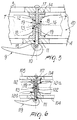
- Fig. 6 illustrates a device in which the elastically compressible element 119 is constituted by a pair of blocks 121a and 121b which are arranged coaxially to the shank 112 of the pusher 113 and have substantially the shape of a truncated cone.
- the pair of blocks has a base which interacts respectively with the inner lateral surface of the first wing 104 of the frame and with the surface of the head 114 and of the pusher 113 that lies opposite to the one that faces the second wing 105 of the chassis.
- a sleeve 122 is arranged between the pair of blocks 121a and 121b, is coaxial to the shank 112 of the pusher 113, and has a degree of elasticity which is equal to, or different from, that of the pair of blocks 121a and 121b; said blocks preferably have a lower degree of compressibility, so as to achieve better grip at the surfaces of the wheels that are adjacent to the rolling surface and also achieve lower wear over time.
- the pusher 113 is again activated by means of a traction-operated actuation element, such as the eccentric lever 119, or by means of technically equivalent elements, which is connected to a second pivot 111 axially aligned with a third pivot 117 which is connected to the second wing 105, as the previous embodiment.
- a traction-operated actuation element such as the eccentric lever 119
- a third pivot 117 which is connected to the second wing 105
- Fig. 7 illustrates an embodiment in which the elastically compressible element 219, arranged coaxially to the shank 212 of the pusher 213 and interposed between the head 214 thereof and the inner lateral surface of the first wing 204 of the frame, has a lateral surface that is shaped approximately complementarily to the surfaces of the adjacent wheels 207; this allows to increase the contact surface between the elastically compressible element 219 and the wheels.
- Fig. 8 illustrates a further embodiment for the elastically compressible element 319, which is interposed between the lateral surface of the first wing 304 and the head 314 of the pusher 313, has a lateral surface which is substantially V-shaped in a longitudinal cross-section, so as to again follow, albeit along a broken-line path, the shape of the adjacent wheels 307 and acting mainly at the surfaces thereof which are adjacent to the rolling surface.
Landscapes
- Footwear And Its Accessory, Manufacturing Method And Apparatuses (AREA)
- Motorcycle And Bicycle Frame (AREA)
Applications Claiming Priority (2)
| Application Number | Priority Date | Filing Date | Title |
|---|---|---|---|
| ITTV970059 | 1997-05-09 | ||
| IT97TV000059A IT1293354B1 (it) | 1997-05-09 | 1997-05-09 | Dispositivo di bloccaggio, particolarmente per ruote di pattini |
Publications (2)
| Publication Number | Publication Date |
|---|---|
| EP0876836A2 true EP0876836A2 (de) | 1998-11-11 |
| EP0876836A3 EP0876836A3 (de) | 2000-02-23 |
Family
ID=11420164
Family Applications (1)
| Application Number | Title | Priority Date | Filing Date |
|---|---|---|---|
| EP98107327A Withdrawn EP0876836A3 (de) | 1997-05-09 | 1998-04-22 | Verriegelungs vorrichtung, insbesondere für Rollschuhräder |
Country Status (3)
| Country | Link |
|---|---|
| US (1) | US5961130A (de) |
| EP (1) | EP0876836A3 (de) |
| IT (1) | IT1293354B1 (de) |
Cited By (1)
| Publication number | Priority date | Publication date | Assignee | Title |
|---|---|---|---|---|
| CN108043012A (zh) * | 2017-12-08 | 2018-05-18 | 福建起步儿童用品有限公司 | 一种步滑自由切换的儿童用滑轮鞋 |
Families Citing this family (10)
| Publication number | Priority date | Publication date | Assignee | Title |
|---|---|---|---|---|
| US5772220A (en) | 1995-06-07 | 1998-06-30 | Gaster; Richard S. | In-line skate conversion apparatus |
| US6279922B1 (en) | 1999-06-04 | 2001-08-28 | Richard S. Gaster | In-line skate wheel disabling apparatus |
| US20040032098A1 (en) * | 1995-06-07 | 2004-02-19 | Richard S. Gaster | In-line skate conversion apparatus |
| US6446982B1 (en) * | 1995-06-07 | 2002-09-10 | Richard S. Gaster | In-line skate conversion apparatus |
| NL1007508C2 (nl) * | 1997-11-10 | 1999-05-11 | Baks Wilhelmus Stefanus Antonius | Rolschaats. |
| FR2772627B1 (fr) * | 1997-12-23 | 2000-03-10 | Salomon Sa | Systeme de liaison rapide d'une chaussure a un article de sport |
| GB2362142B (en) * | 2000-05-10 | 2002-07-03 | Den Liang Ind Co Ltd | Folding structure for handle of a handle-controlled skate board |
| DE20113444U1 (de) * | 2001-08-13 | 2002-03-21 | Jablonski, Zbigniew, 50859 Köln | Variable, selbsteinstellbare, profilierte Bremsbacken mit integrierter Feststellvorrichtung und Druckübertragungs-Fersenbügeleinheit für Inline-Skater |
| EP1314463A1 (de) * | 2001-11-26 | 2003-05-28 | Andreas Greber | Inline-Rollerskate mit durch Schnellverschluss befestigten Rollen |
| KR200448180Y1 (ko) | 2007-12-02 | 2010-03-25 | 정자연 | 인라인스케이트의 안전을 위한 보조기구 |
Citations (5)
| Publication number | Priority date | Publication date | Assignee | Title |
|---|---|---|---|---|
| US2725238A (en) | 1952-01-29 | 1955-11-29 | Samuel S Day | Training-type roller skate |
| US3900203A (en) | 1974-07-08 | 1975-08-19 | Adolph F Kukulowicz | Tandem wheeled roller skate |
| US4312514A (en) | 1980-01-07 | 1982-01-26 | Isadore Horowitz | Roller skate brake |
| US5503433A (en) | 1994-11-03 | 1996-04-02 | Lachapelle; Luc | Device for blocking wheels of roller skates |
| US5511805A (en) | 1994-05-12 | 1996-04-30 | Mcgrath; Neal | Braking apparatus for use with in-line roller skates |
Family Cites Families (6)
| Publication number | Priority date | Publication date | Assignee | Title |
|---|---|---|---|---|
| US5239941A (en) * | 1992-07-27 | 1993-08-31 | Gary Chibi | Braking system for in-line roller skates |
| US5437466B1 (en) * | 1993-07-19 | 1997-11-18 | K 2 Corp | In-line roller skate |
| IT1266082B1 (it) * | 1993-11-09 | 1996-12-20 | Nordica Spa | Struttura di pattino con ruote in linea |
| DE19525573C1 (de) * | 1995-07-13 | 1996-09-26 | Joachim Schug | Bremssystem für einen einspurigen Rollschuh |
| US5595392A (en) * | 1995-07-31 | 1997-01-21 | Casillas; Anthony | In-line roller ice skate combination |
| US5769432A (en) * | 1995-12-13 | 1998-06-23 | Tybinkowski; Andrew P. | Lock assembly for in-line skate |
-
1997
- 1997-05-09 IT IT97TV000059A patent/IT1293354B1/it active IP Right Grant
-
1998
- 1998-04-22 EP EP98107327A patent/EP0876836A3/de not_active Withdrawn
- 1998-04-23 US US09/064,767 patent/US5961130A/en not_active Expired - Fee Related
Patent Citations (5)
| Publication number | Priority date | Publication date | Assignee | Title |
|---|---|---|---|---|
| US2725238A (en) | 1952-01-29 | 1955-11-29 | Samuel S Day | Training-type roller skate |
| US3900203A (en) | 1974-07-08 | 1975-08-19 | Adolph F Kukulowicz | Tandem wheeled roller skate |
| US4312514A (en) | 1980-01-07 | 1982-01-26 | Isadore Horowitz | Roller skate brake |
| US5511805A (en) | 1994-05-12 | 1996-04-30 | Mcgrath; Neal | Braking apparatus for use with in-line roller skates |
| US5503433A (en) | 1994-11-03 | 1996-04-02 | Lachapelle; Luc | Device for blocking wheels of roller skates |
Cited By (2)
| Publication number | Priority date | Publication date | Assignee | Title |
|---|---|---|---|---|
| CN108043012A (zh) * | 2017-12-08 | 2018-05-18 | 福建起步儿童用品有限公司 | 一种步滑自由切换的儿童用滑轮鞋 |
| CN108043012B (zh) * | 2017-12-08 | 2019-04-05 | 福建起步儿童用品有限公司 | 一种步滑自由切换的儿童用滑轮鞋 |
Also Published As
| Publication number | Publication date |
|---|---|
| US5961130A (en) | 1999-10-05 |
| ITTV970059A0 (it) | 1997-05-09 |
| IT1293354B1 (it) | 1999-02-25 |
| EP0876836A3 (de) | 2000-02-23 |
| ITTV970059A1 (it) | 1998-11-09 |
Similar Documents
| Publication | Publication Date | Title |
|---|---|---|
| US5226673A (en) | Braking assembly and method | |
| EP0876836A2 (de) | Vorrichtung zur Verriegelung, insbesondere für Rollschuhräder | |
| US5375859A (en) | Mechanical brake for in-line roller skate | |
| US5351974A (en) | In-line skate braking assembly and method | |
| US5335924A (en) | Retractable break pad mechanism for in-line skates | |
| US5895061A (en) | In-line roller skate with removable boot | |
| JP2735775B2 (ja) | スケート用ブレーキ装置 | |
| US5403021A (en) | Brake assembly for in-line roller skates | |
| US5246238A (en) | Roller skate wheel | |
| US5239941A (en) | Braking system for in-line roller skates | |
| US5253883A (en) | Progressively actuated brake for a roller skate | |
| CA2107347A1 (en) | Skate with aligned wheels | |
| CA2103115A1 (en) | Braking device particularly for skates | |
| US5657999A (en) | In-line roller blade braking device | |
| CA2135364A1 (en) | In-line skate | |
| US5401038A (en) | Mechanical brake for in-line roller skates | |
| AU671915B2 (en) | Braking device for roller skates | |
| WO1993012847A1 (en) | Skate with aligned wheels | |
| US5029882A (en) | Roller skates | |
| US6065761A (en) | In-line roller skate equipped with a brake acting on the wheels | |
| EP0815906B1 (de) | Rollschuh mit Bremskontrolleinrichtung | |
| US5908197A (en) | Braking assembly for an in-line roller skate | |
| US6131922A (en) | Roller skate brake arrangement | |
| US3442523A (en) | Roller skate wheel assembly | |
| US20100032917A1 (en) | Inline roller skate configurations |
Legal Events
| Date | Code | Title | Description |
|---|---|---|---|
| PUAI | Public reference made under article 153(3) epc to a published international application that has entered the european phase |
Free format text: ORIGINAL CODE: 0009012 |
|
| AK | Designated contracting states |
Kind code of ref document: A2 Designated state(s): DE FR IT |
|
| AX | Request for extension of the european patent |
Free format text: AL;LT;LV;MK;RO;SI |
|
| PUAL | Search report despatched |
Free format text: ORIGINAL CODE: 0009013 |
|
| AK | Designated contracting states |
Kind code of ref document: A3 Designated state(s): AT BE CH CY DE DK ES FI FR GB GR IE IT LI LU MC NL PT SE |
|
| AX | Request for extension of the european patent |
Free format text: AL;LT;LV;MK;RO;SI |
|
| RAP1 | Party data changed (applicant data changed or rights of an application transferred) |
Owner name: BENETTON GROUP S.P.A. |
|
| 17P | Request for examination filed |
Effective date: 20000804 |
|
| AKX | Designation fees paid |
Free format text: DE FR IT |
|
| STAA | Information on the status of an ep patent application or granted ep patent |
Free format text: STATUS: THE APPLICATION IS DEEMED TO BE WITHDRAWN |
|
| 18D | Application deemed to be withdrawn |
Effective date: 20021101 |