EP0876265B1 - Bumper, and the fabrication thereof - Google Patents
Bumper, and the fabrication thereof Download PDFInfo
- Publication number
- EP0876265B1 EP0876265B1 EP97901848A EP97901848A EP0876265B1 EP 0876265 B1 EP0876265 B1 EP 0876265B1 EP 97901848 A EP97901848 A EP 97901848A EP 97901848 A EP97901848 A EP 97901848A EP 0876265 B1 EP0876265 B1 EP 0876265B1
- Authority
- EP
- European Patent Office
- Prior art keywords
- portions
- section
- bumper
- blank
- wall portion
- Prior art date
- Legal status (The legal status is an assumption and is not a legal conclusion. Google has not performed a legal analysis and makes no representation as to the accuracy of the status listed.)
- Expired - Lifetime
Links
Images


Classifications
-
- B—PERFORMING OPERATIONS; TRANSPORTING
- B60—VEHICLES IN GENERAL
- B60R—VEHICLES, VEHICLE FITTINGS, OR VEHICLE PARTS, NOT OTHERWISE PROVIDED FOR
- B60R19/00—Wheel guards; Radiator guards, e.g. grilles; Obstruction removers; Fittings damping bouncing force in collisions
- B60R19/02—Bumpers, i.e. impact receiving or absorbing members for protecting vehicles or fending off blows from other vehicles or objects
- B60R19/18—Bumpers, i.e. impact receiving or absorbing members for protecting vehicles or fending off blows from other vehicles or objects characterised by the cross-section; Means within the bumper to absorb impact
- B60R2019/1806—Structural beams therefor, e.g. shock-absorbing
- B60R2019/1813—Structural beams therefor, e.g. shock-absorbing made of metal
- B60R2019/182—Structural beams therefor, e.g. shock-absorbing made of metal of light metal, e.g. extruded
Definitions
- the present invention relates to a method for fabrication of a structural beam or bumper according to the precharacterizing clause of claim 1. Such a method is known from WO93/04897.
- the invention relates to a beam or bumper, fabricated by the said method.
- the cross-section of a center portion may be a lot larger than of terminal portions. Therefore, it is necessary to compress the terminal portions to a very high extent.
- the motive of the present invention is the task of providing a bumper which combines the protection of a vehicle and persons in the vehicle upon collision.
- the invention has for its objective to provide a bumper which excels in high torsional stiffness, combined with great bending softness.
- a further objective of the present invention is to provide a bumper rendering the possibility for rational and structural sturdy attachment to the frame of the vehicle.
- An object of the present invention is also to provide an elastic and relatively slender structural beam or bumper which in relation to previously known profile based, closed bumpers, may absorb more elastic bending energy in relation to quantity of used material.
- the invention relates to a method which renders a rational production of bumpers of said type, the method at the same time being specifically favourable for high rate forming in a production line.
- a specific embodiment of such a bumper may involve that the cross section at each side of the centre comprises an outer wall portion, an arched inner wall portion, as well as yoke portions extending substantially perpendicularly from said outer wall portion that said cross section at the centre has a substantially trapeze shaped cross section comprising an outer wall portion having substantially the same hight as said intermediate cross section and an inner wall portion of lesser hight, as well as substantially slanted yoke portions therebetween, and that said cross section at the terminal portions has an outer wall portion having substantially the same hight as said intermediate cross section and an inner wall portion having larger, equal or less hight and having intermediate, arched or wavy yoke portions.
- the trapeze shaped cross section at the centre can then by simple processing of the original yoke portions and the arched surfaces of the inner wall be given a predetermined shape, at the same time as said basic cross section at each side of the centre will allow for easier manipulation of the shape of the product. Further, with said basic cross section on each side of the centre it is possible to undertake a controlled compression for folding of the areas at each of the terminal portions, so that the latter constitute the more slender part of the bumper.
- this type of bumper comprises a closed cross section having a front wall portion, a rear wall portion and intermediate yoke portions, said front and rear portions having a relatively large wall thickness compared to the wall thickness of the intermediate yoke portions.
- front wall portion can be substantially straight, or be provided with a more or less contoured shape.
- terminal portions may be so prepared that they merge into attachment portions which are provided with individual parallel surfaces against associated side beam for attachment thereto.
- the bumper may be prepared substantially symmetrically about a central plane extending in the longitudinal direction of the car, and be provided with an outer mantle of plastic material.
- a method for manufacturing a structural beam or bumper of the type as stated in the preamble will involve starting off with an extruded profile having a given basic cross section and by the further processing of this profiled blank letting the latter basic cross section be maintained on each side of the centre, whereas in the area of the centre letting the basic cross section be processed to a more or less protruding cross section, at the same time as letting the profile at the terminal portions be processed to a more compressed or folded cross section.
- the method is to the fact that one starts off with a cross section which at each side of the centre has an intermediate cross section comprising an outer wall portion, an arched inner wall portion, as well as yoke portions extending substantially perpendicularly from the outer wall portion, that the cross section at the centre is processed by substantially outwardly pressing of the yoke portion for the provision of a substantially trapeze shaped cross section comprising an outer wall portion having substantially the same hight as the intermediate cross section and an inner wall portion of smaller hight, as well as substantially inclined yoke portions therebetween, and that at the terminal portions the intermediate cross section is processed to an outer wall portion having substantially the same hight as said intermediate cross section and an inner wall portion having larger, equal or less hight, the intermediate yoke being processed to bulge or bend outwardly in relation to said outer wall portion.
- the extruded blank to be used which has a closed cross section and a front wall portion and a rear wall portion, as well as intermediate yoke portions, also has front and rear wall portions having a relatively larger wall thickness of said intermediate yoke portions.
- the front wall portion may be substantially straight, or have a more or less contoured form.
- terminal portions may be further processed or simultaneously processed to comprise attachment portions which are provided with a net parallel surface related to appropriate side beams of the vehicle.
- the method is to the fact of manufacturing a bumper profile which is substantially symmetrical about a centre plane extending in the longitudinal direction of the car, at the same time as the finished bumper will be provided with an outer mantle of plastic material.
- a further feature according to the method according to the invention is to the fact that the bumper is manufactured by outer processing, said outer processing taking place by means of mechanical tools.
- hydroforming can be used.
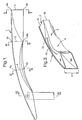
- Fig. 1 is a schematic view as seen from above of a symmetrical half of a structural beam, especially a bumper beam according to the invention.
- Fig. 2 is a side view of the bumper rail half according to Fig. 1.
- Fig. 3 is a perspective view of a cut-out of the terminal portion of the bumper rail illustrated in Figures 1 and 2.
- Figures 4, 5, 6 and 7 are cross sections taken along the lines IV-IV, V-V, VI-VI as well as VII-VII, respectively, according to Fig. 1.
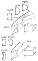
- Fig. 8 is a perspective view of a bumper rail having a specifically formed terminal portion for net parallel attachment, Figures 8A, 8B and 8C defining the various cross section forms along said bumper rail, Figures 8AX, 8AY and 8AZ defining various forms of the outer wall portion.
- Fig. 9 is a perspective cut-out of a terminal portion of a bumper rail provided with attachment portions for non-net parallel attachment.
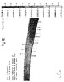
- Figures 10-12 illustrate examples of calculation models for an embodiment of a structural beam according to the invention, said model being compiled according to the "finite element" method.
- FIGs 1-7 there is illustrated an example of a structural beam, especially a bumper beam according to the invention, Fig. 1 illustrating schematically a view as seen from above of a symmetric half of said rail 1, whereas Fig. 2 illustrates a side view of the same rail, and Fig. 3 illustrates perspectively details of the terminal portion of the bumper rail 1 illustrated in Figures 1 and 2.
- Figures 4, 5, 6 and 7 represent cross sections taken along the lines IV-IV, V-V, VI-VI, as well as VII-VII, respectively, illustrated in Fig. 1.
- the bumper rail 1 is in Figures 1-7 illustrated in its finished processed form, and is as such adapted for absorbing collision energy and forces when used in a car, it being preferably as a bumper, but also as a supporting beam in the overall structure of the car.
- the bumper 1 is made from a complete and hollow extruded blank which is manufactured from an extrudable material, for example aluminum, or any other materials or mixtures having corresponding extrudable and strength-related properties.
- the blank has in its initial form a basic cross section 2 of the type which is specifically illustrated in Fig. 4, and which comprises an outer wall portion 2a of substantially straight design and having a hight H, an arched inner portion 2b as well as yoke portions 2c extending substantially perpendicularly from the outer wall portion 2a.
- This basic cross section 2 is on both sides of the centre, see IV-IV in Fig. 1 and Fig. 4, according to the present invention maintained so to say unchanged, whereas at the centre portion itself, see V-V in Fig. 1 and Fig.
- the basic cross section has been given an outwardly pressed cross section 3, whereas in the areas of each of the terminal portions, here at section VI-VI in Fig. 1, see also Fig. 6, the basic cross section 2 has been compressed or folded to a further cross section 4, which is different from the basic cross section.
- the bumper rail 1 is manufactured on the basis of a basic cross section on each side of the centre, and an outwardly pressed cross section at the centre in relation to said basic cross section, as well as a compressed or folded cross section in the areas of each of the terminal portions.
- outer wall portion can deviate from the wall portion 2a as illustrated here, namely by being substantially straight, or be designed with a more or less contoured shape.
- the cross section 3 at the centre is pressed out to a substantially trapeze shaped cross section 3, comprising a straight inner wall portion 3a having substantially the same hight H as said inner wall portion 2b of said intermediate cross section 2, and having an inner wall portion 3b of lesser hight, at the same time as there are provided substantially inclined yoke portions 3c between said straight inner wall portion 3a and said outer wall portion 3b.
- the cross section 4 at the terminal portions, see specifically Fig. 6, is in this embodiment compressed or folded to comprise a straight outer wall portion 4a having substantially the same hight H as the outer wall portion 2a for said intermediate cross section 2, see Fig. 4, as well as an inner wall portion 4b which is here folded out to a larger hight H1 than said outer wall portion 4a, and then with intermediate arched or wavy yoke portions 4c.
- cross section 4 at the terminal portions can have an inner wall portion which can be equal or less than said hight corresponding to the hight H for said intermediate cross section 2, all in dependence of the desired final form which the bumper or the power beam according to the present invention is to be given.
- the starting point is a cross section 2, see Fig. 4, which constitutes a closed cross section, the front wall portion 2a and the rear wall portion 2b being provided with or comprising portions having a larger wall thickness than the wall thickness of the intermediate yoke portions 2c.
- profile or bumper rail 1 can be made substantially symmetrical about a centre plane running in the longitudinal direction of the vehicle, and beyond this be provided with an outer mantle of plastic material.
- the structural beam according to the invention is to be used as a structure element in the vehicle as such, this symmetrical design can appropriately be alleviated.
- terminal portions may merge into attachment portions, as this is specifically illustrated in Figures 8 and 9, said attachment portions being provided with a net parallel surface against side beams of the vehicle.
- Fig. 8 with its sections 8A-8C illustrates a specific design of the terminal portions for net parallel attachment, and the sections illustrated in Figures 8A, 8B and 8C are designed substantially in accordance with the sections as discussed in connection with Figures 4, 5 and 6. However, in Fig. 8C there are illustrated alternative a and alternative b for various bendings of the processed section 5 at the terminal portions.
- Fig. 8AX illustrated a variant of the basic cross section comprising an outer portion which deviates from being straight, but which rather has an outwardly bulging contour
- Fig. 8AY illustrates an asymmetrical outer portion
- Fig. 8AZ illustrates a substantially mirror symmetrical section having an inwardly bulging contour.
- Fig. 9 there is illustrates a perspective view of a terminal portion of a bumper rail provided with attachment portions for non-net parallel attachment.
- the processing of the blank can take place by a first stretching to the basic shape, especially a modestly arched shape in the longitudinal direction of the blank, whereafter the profile is simultaneously processed at the centre portion and the terminal portions, but with the opposite processing direction for said portions.
- said processing may be to the fact that the blank is processed by means of hydroforming.
- Figures 10-12 there is illustrated examples of calculated models of an embodiment of a structural beam according to the invention.
- Figures 10 and 11 illustrate various perspective views of the model which is compiled according to the "finite element" method.
- Fig. 12 illustrates the stress distribution in load case “barrier", and then more specifically equivalent stresses at "fringe” levels.
Description
Claims (16)
- A method for fabrication of a structural beam or bumper, especially for a vehicle, comprising an elongated profile which upon collision is adapted for absorbing collision energy and forces,
comprising the steps of
providing a complete and hollow blank having, along its more or less arched extension, a center portion (3), side portions (2) at each side of said center portion (3) and terminal portions (4) and
processing said blank to a compressed or folded cross section in said terminal portion (4),
characterized by the steps of
processing said blank to an outwardly pressed cross section in said center portion (3) and
processing said blank with a substantially unchanged basic cross section in each side portion (2). - The method of claim 1,
characterized by the step of processing said blank to an arched extension. - The method of claim 1 or 2,
characterized in that there is used a hollow blank the inside thereof being defined by a first wall portion (2a), an arched second wall portion (2b) and yoke portions (2c) extending substantially perpendicularly from the outer wall portion (2a), wherein
said center portion (3) is processed to a substantially trapeze shaped cross section comprising a first center wall portion (3a) having substantially the same height (H) as said blank, a second center wall portion (3b) of less height, and substantially inclined center yoke portions (3c) therebetween, and
said terminal portions (4) are processed to a cross section profile comprising a first terminal wall portion (4a) having the same height (H) as said blank, a second terminal wall portion (4b) having a larger, equal or less height (H) and intermediate, arched or wavy terminal yoke portions (4c). - The method of any preceding claim,
characterized in that as said blank there is used an extruded profile (2) having a closed cross section, said first and second wall portions (2a, 2b) having a larger wall thickness than the wall thickness of said intermediate yoke portions (2c). - The method of any preceding claim,
characterized in that the end portions of said blank are processed to attachment portions which are provided with a net parallel surface for attachment to a side beam in the vehicle. - The method of any preceding claim,
characterized in that the blank is processed to a profile which is substantially symmetrical about a center plane running in the longitudinal direction of the vehicle, and is provided with an outer mantle of plastic material. - The method of any preceding claim,
characterized in that the processing of the blank takes place in a first stretching or pressing to a main shape, especially a vaguely arched shape in the longitudinal direction of the blank, whereafter the profile at the same time or in a subsequent processing operation is processed at the center portion (3) and the terminal portions (4), but in opposite processing direction for said portions. - The method of any preceding claim,
characterized in that the blank is processed by an outer processing, for example by means of mechanical tools. - The method of any preceding claim,
characterized in that the blank is processed by means of hydroforming. - A structural beam or bumper, fabricated by the method of any preceding claim.
- The beam or bumper of claim 10, especially for a vehicle, comprising an elongated profile which upon collision is adapted for absorbing collision energy and forces, the beam or bumper being prepared from a complete and hollow blank and being further provided with different cross sections along its more or less arched extension, wherein
said beam or bumper comprises a center portion (3), side portions (2) at each side of said center portion (3) and terminal portions (4) and
said beam or bumper has a compressed or folded cross section at each of said terminal portions (4), and that the beam or bumper in addition has a substantially unchanged basic cross section at each of said side portions (2), and has an outwardly pressed cross section relative to said basic cross section at said center portion (3). - The beam or bumper of claim 10 or 11,
characterized in that
it has an arched extension. - The beam or bumper of any of claims 10 to 12,
characterized in that
the inside of each of said side portions (2) is defined by a first wall portion (2a), an arched inner wall portion (2b), and yoke portions (2c) extending substantially perpendicularly from said outer wall portion (2a),
said center portion (3) has a substantially trapeze shaped cross section defined by a first center wall portion (3a) having the same height (H) as said side portions (2), a second center wall portion (3b) of less height, and substantially slanted yoke portions (3c) therebetween, and
said terminal portions (4) have a first terminal wall portion (4a) having substantially the same height (H) as said side portions (2), a second terminal wall portion (4b) having larger, equal or less height (H1) and intermediate, arched or wavy yoke portions (4c). - The beam or bumper of any of claims 10 to 13,
characterized in that it comprises a closed cross section (2) wherein said first and second wall portions (2a, 2b) have a relatively larger wall thickness than the wall thickness of said intermediate yoke portions (2c). - The beam or bumper of any of claims 10 to 14,
characterized in that said terminal portions (4) merge into attachment portions which are provided with a net parallel surface for attachment to a side beam in the vehicle. - The beam or bumper of any of claims 10 to 15,
characterized in that
its profile is provided substantially symmetrical about a center plane running in the longitudinal direction of the vehicle, and
it is provided with an outer mantle of plastic material.
Applications Claiming Priority (3)
| Application Number | Priority Date | Filing Date | Title |
|---|---|---|---|
| NO960288 | 1996-01-24 | ||
| NO960288A NO960288D0 (en) | 1996-01-24 | 1996-01-24 | Stötfangerskinne |
| PCT/NO1997/000011 WO1997027082A1 (en) | 1996-01-24 | 1997-01-14 | Bumper, and the fabrication thereof |
Publications (2)
| Publication Number | Publication Date |
|---|---|
| EP0876265A1 EP0876265A1 (en) | 1998-11-11 |
| EP0876265B1 true EP0876265B1 (en) | 2002-08-14 |
Family
ID=19898962
Family Applications (1)
| Application Number | Title | Priority Date | Filing Date |
|---|---|---|---|
| EP97901848A Expired - Lifetime EP0876265B1 (en) | 1996-01-24 | 1997-01-14 | Bumper, and the fabrication thereof |
Country Status (6)
| Country | Link |
|---|---|
| US (1) | US5997058A (en) |
| EP (1) | EP0876265B1 (en) |
| AU (1) | AU1559897A (en) |
| DE (1) | DE69714705T2 (en) |
| NO (1) | NO960288D0 (en) |
| WO (1) | WO1997027082A1 (en) |
Cited By (1)
| Publication number | Priority date | Publication date | Assignee | Title |
|---|---|---|---|---|
| DE102015114105A1 (en) | 2015-08-25 | 2017-03-16 | Benteler Automobiltechnik Gmbh | Impact beam for a motor vehicle and method for its production |
Families Citing this family (37)
| Publication number | Priority date | Publication date | Assignee | Title |
|---|---|---|---|---|
| SE509617C2 (en) * | 1996-09-13 | 1999-02-15 | Peter Benson | Beam-shaped object, such as a bumper and the like |
| NO974375L (en) * | 1997-09-22 | 1999-03-23 | Norsk Hydro As | Bumper, and manufacture of the same |
| AU5722299A (en) * | 1998-09-18 | 2000-04-10 | Cosma International Inc. | Bumper beam assembly and method |
| DE19853128C2 (en) * | 1998-11-18 | 2003-04-03 | Daimler Chrysler Ag | Bumper arrangement of a motor vehicle and method for its production |
| NO990503D0 (en) * | 1999-02-03 | 1999-02-03 | Norsk Hydro As | Bumper and method of making the same |
| NO993034D0 (en) * | 1999-06-18 | 1999-06-18 | Norsk Hydro As | Beam and method of manufacturing the same |
| US6349521B1 (en) * | 1999-06-18 | 2002-02-26 | Shape Corporation | Vehicle bumper beam with non-uniform cross section |
| SE516760C2 (en) | 1999-12-14 | 2002-02-26 | Accra Teknik Ab | Bumper beam |
| SE516762C2 (en) | 1999-12-14 | 2002-02-26 | Accra Teknik Ab | Bumper beam and method of manufacturing the same |
| US6851731B2 (en) | 2001-05-29 | 2005-02-08 | Inalfa Roof Systems Group B.V. | Crash energy absorbing element |
| EP1262374B1 (en) * | 2001-05-29 | 2004-08-25 | Inalfa Industries B.V. | Crash energy absorbing element |
| US6644701B2 (en) | 2002-01-14 | 2003-11-11 | Shape Corporation | Bumper energy absorber with foam and non-foam pieces |
| ES2261899T3 (en) * | 2002-03-04 | 2006-11-16 | ALCAN TECHNOLOGY & MANAGEMENT LTD. | BUMPER FOR A VEHICLE. |
| US6663150B1 (en) * | 2002-06-06 | 2003-12-16 | Netshape Corporation | Bumper with integrated energy absorber and beam |
| US6672635B2 (en) | 2002-06-06 | 2004-01-06 | Netshape Corporation | Bumper with integrated foam and non-foam components |
| NO20024789D0 (en) * | 2002-10-03 | 2002-10-03 | Norsk Hydro As | Bumper |
| SE527380C2 (en) * | 2003-06-06 | 2006-02-21 | Gestamp Hardtech Ab | Bumper beam for vehicles |
| US7077439B2 (en) * | 2003-08-25 | 2006-07-18 | General Motors Corporation | Vehicle bumper and method of making same |
| US7108303B2 (en) * | 2004-04-07 | 2006-09-19 | Pullman Industries, Inc. | Crushed profile bumper and method for producing |
| DE102004019149A1 (en) * | 2004-04-21 | 2005-11-24 | Daimlerchrysler Ag | Multi-part bumper unit |
| US7163241B2 (en) * | 2004-06-25 | 2007-01-16 | F.Tech R&D North America Inc. | Vehicle bumper beam having non-uniform cross sections |
| US6971691B1 (en) | 2004-06-25 | 2005-12-06 | Shape Corporation | Vehicle bumper beam |
| US6986536B1 (en) * | 2004-06-25 | 2006-01-17 | Shape Corporation | Vehicle bumper beam |
| CN1976832B (en) * | 2004-07-01 | 2012-03-28 | 麦格纳国际公司 | Bumper beam for a motor vehicle |
| US7210717B1 (en) | 2005-03-31 | 2007-05-01 | Ford Global Technologies, Llc | Lightweight bumper for automobiles |
| US7066508B1 (en) | 2005-03-31 | 2006-06-27 | Ford Global Technologies, Llc | Bumper cross-section with hinges |
| SE527968C2 (en) * | 2005-05-25 | 2006-07-25 | Gestamp Hardtech Ab | Bow-formed bumper beam for vehicle, has hat profile with central flange, two webs and side flanges, where flanges have bent edges in area between fastening areas, and bent edges have transverse dents at beginning of bent edges |
| JP4546496B2 (en) * | 2007-03-09 | 2010-09-15 | 株式会社丸順 | Bumper beam for automobile |
| US20090102208A1 (en) * | 2007-10-17 | 2009-04-23 | Huensick Min | Back beam structure for vehicle |
| JP5042904B2 (en) * | 2008-04-08 | 2012-10-03 | 昭和電工株式会社 | Bumper reinforcement for vehicles |
| US8660756B2 (en) * | 2010-01-11 | 2014-02-25 | Honda Motor Co., Ltd. | Collision mitigation system |
| JP5584039B2 (en) * | 2010-07-30 | 2014-09-03 | アイシン精機株式会社 | Bumper inhose and bumper device for vehicle |
| DE102010050013B4 (en) * | 2010-11-02 | 2020-07-09 | Benteler Automobiltechnik Gmbh | Bumper assembly for a motor vehicle |
| CN103328272B (en) | 2011-01-24 | 2016-03-09 | 肯联铝业辛根有限责任公司 | There is the tubular beam of the vehicle structure improving collision performance |
| JP5689034B2 (en) * | 2011-07-07 | 2015-03-25 | 豊田鉄工株式会社 | Bumper reinforcement for vehicles |
| GB2519810A (en) * | 2013-10-31 | 2015-05-06 | Gm Global Tech Operations Inc | Vehicle front structure |
| DE102016101159A1 (en) * | 2016-01-22 | 2017-07-27 | Benteler Automobiltechnik Gmbh | Method for producing a motor vehicle component from an extruded light metal profile |
Family Cites Families (13)
| Publication number | Priority date | Publication date | Assignee | Title |
|---|---|---|---|---|
| US1985113A (en) * | 1933-05-03 | 1934-12-18 | Neal G Smith | Bumper shoe |
| JPS56128245A (en) * | 1980-02-22 | 1981-10-07 | Honda Motor Co Ltd | Impact absorbing bumper for vehicle |
| FR2531022A1 (en) * | 1982-07-27 | 1984-02-03 | Techni Plaste Sa | Automobile vehicle bumper and means for mounting it to the chassis of the vehicle. |
| US4961603A (en) * | 1989-12-19 | 1990-10-09 | Ford Motor Company | Vehicle bumper system |
| NO173538C (en) * | 1991-09-06 | 1993-12-29 | Norsk Hydro As | Construction beam and method of production of the same |
| DE4214557A1 (en) * | 1992-04-28 | 1993-11-04 | Mannesmann Ag | Method for hydraulic expansion of closed hollow profiles - processes blank, which is pre-profiled before hydraulic expansion |
| DE4306824A1 (en) * | 1993-03-04 | 1994-09-08 | Norsk Hydro As | Impact beam for stiffening a motor vehicle wall part and wall part which is equipped with such an impact beam |
| JPH07205732A (en) * | 1994-01-13 | 1995-08-08 | Yamakawa Ind Co Ltd | Bumper reinforcement and manufacture thereof |
| SE503450C2 (en) * | 1994-01-26 | 1996-06-17 | Plannja Hardtech Ab | Bumper beam |
| NO941974D0 (en) * | 1994-05-27 | 1994-05-27 | Raufoss As | Bumper, as well as manufacture of the same |
| JPH0860285A (en) * | 1994-06-16 | 1996-03-05 | Furukawa Electric Co Ltd:The | Bumper reinforcement made of aluminum alloy and its production |
| DE59500982D1 (en) * | 1995-03-22 | 1997-12-18 | Porsche Ag | Hollow profile for a support structure of a motor vehicle |
| US5799991A (en) * | 1996-10-23 | 1998-09-01 | Concept Analysis Corporation | Molded bumper system with reinforcement beam |
-
1996
- 1996-01-24 NO NO960288A patent/NO960288D0/en unknown
-
1997
- 1997-01-14 DE DE69714705T patent/DE69714705T2/en not_active Expired - Lifetime
- 1997-01-14 US US09/117,158 patent/US5997058A/en not_active Expired - Lifetime
- 1997-01-14 WO PCT/NO1997/000011 patent/WO1997027082A1/en active IP Right Grant
- 1997-01-14 EP EP97901848A patent/EP0876265B1/en not_active Expired - Lifetime
- 1997-01-14 AU AU15598/97A patent/AU1559897A/en not_active Abandoned
Cited By (3)
| Publication number | Priority date | Publication date | Assignee | Title |
|---|---|---|---|---|
| DE102015114105A1 (en) | 2015-08-25 | 2017-03-16 | Benteler Automobiltechnik Gmbh | Impact beam for a motor vehicle and method for its production |
| US9975506B2 (en) | 2015-08-25 | 2018-05-22 | Benteler Automobiltechnik Gmbh | Impact beam for a motor vehicle and method for production thereof |
| DE102015114105B4 (en) | 2015-08-25 | 2018-11-29 | Benteler Automobiltechnik Gmbh | Impact beam for a motor vehicle and method for its production |
Also Published As
| Publication number | Publication date |
|---|---|
| EP0876265A1 (en) | 1998-11-11 |
| US5997058A (en) | 1999-12-07 |
| NO960288D0 (en) | 1996-01-24 |
| DE69714705T2 (en) | 2003-05-08 |
| AU1559897A (en) | 1997-08-20 |
| DE69714705D1 (en) | 2002-09-19 |
| WO1997027082A1 (en) | 1997-07-31 |
Similar Documents
| Publication | Publication Date | Title |
|---|---|---|
| EP0876265B1 (en) | Bumper, and the fabrication thereof | |
| US6343820B1 (en) | Bumper, and the fabrication thereof | |
| US20060075636A1 (en) | Method for producing a bumper exhibiting a crushed profile | |
| JP4295208B2 (en) | Bumper with integrated foam and non-foam components | |
| US5577796A (en) | Structural beam and method of manufacture thereof | |
| US6659518B2 (en) | Bumper bar for a motor vehicle with an intermediate web | |
| US6851731B2 (en) | Crash energy absorbing element | |
| CA2280440C (en) | Automotive vehicle body structure demonstrating a controlled reaction load | |
| CA2032949C (en) | Frame for a motor vehicle door and a door including the frame | |
| PL197994B1 (en) | Bumper beam assembly and method | |
| US20080048462A1 (en) | Thermoplastic composite bumper system | |
| US6296287B1 (en) | Curved elongate member of closed sectional shape and method and apparatus for fabricating the same | |
| US6813920B2 (en) | Method for producing a bumper reinforcement | |
| EP0870650B1 (en) | Apparatus and method for making an automotive bumper beam | |
| WO2006000074A1 (en) | Vehicle bumper beam having non-uniform cross sections | |
| JP2004533960A (en) | Stamped bending bumper beam | |
| EP1154915B1 (en) | Bumper beam | |
| US6964096B2 (en) | Method of manufacturing a structural member and a member provided by such method | |
| US6247344B1 (en) | Method of producing a hollow profile with flange | |
| EP1262374B1 (en) | Crash energy absorbing element | |
| EP1194317B1 (en) | Impact beam and method of manufacturing the same | |
| CA2416770C (en) | Lightweight support for bumpers | |
| JP3562919B2 (en) | Shock absorbing bumper | |
| MXPA97006212A (en) | Skeleton of address for vehicle of mo | |
| JPH02265510A (en) | Head rest |
Legal Events
| Date | Code | Title | Description |
|---|---|---|---|
| PUAI | Public reference made under article 153(3) epc to a published international application that has entered the european phase |
Free format text: ORIGINAL CODE: 0009012 |
|
| 17P | Request for examination filed |
Effective date: 19980723 |
|
| AK | Designated contracting states |
Kind code of ref document: A1 Designated state(s): DE FR GB IT SE |
|
| 17Q | First examination report despatched |
Effective date: 20000322 |
|
| GRAG | Despatch of communication of intention to grant |
Free format text: ORIGINAL CODE: EPIDOS AGRA |
|
| GRAG | Despatch of communication of intention to grant |
Free format text: ORIGINAL CODE: EPIDOS AGRA |
|
| GRAH | Despatch of communication of intention to grant a patent |
Free format text: ORIGINAL CODE: EPIDOS IGRA |
|
| GRAH | Despatch of communication of intention to grant a patent |
Free format text: ORIGINAL CODE: EPIDOS IGRA |
|
| GRAA | (expected) grant |
Free format text: ORIGINAL CODE: 0009210 |
|
| AK | Designated contracting states |
Kind code of ref document: B1 Designated state(s): DE FR GB IT SE |
|
| PG25 | Lapsed in a contracting state [announced via postgrant information from national office to epo] |
Ref country code: IT Free format text: LAPSE BECAUSE OF FAILURE TO SUBMIT A TRANSLATION OF THE DESCRIPTION OR TO PAY THE FEE WITHIN THE PRE;WARNING: LAPSES OF ITALIAN PATENTS WITH EFFECTIVE DATE BEFORE 2007 MAY HAVE OCCURRED AT ANY TIME BEFORE 2007. THE CORRECT EFFECTIVE DATE MAY BE DIFFERENT FROM THE ONE RECORDED.SCRIBED TIME-LIMIT Effective date: 20020814 |
|
| REG | Reference to a national code |
Ref country code: GB Ref legal event code: FG4D |
|
| REF | Corresponds to: |
Ref document number: 69714705 Country of ref document: DE Date of ref document: 20020919 |
|
| PG25 | Lapsed in a contracting state [announced via postgrant information from national office to epo] |
Ref country code: SE Free format text: LAPSE BECAUSE OF FAILURE TO SUBMIT A TRANSLATION OF THE DESCRIPTION OR TO PAY THE FEE WITHIN THE PRESCRIBED TIME-LIMIT Effective date: 20021114 |
|
| ET | Fr: translation filed | ||
| PG25 | Lapsed in a contracting state [announced via postgrant information from national office to epo] |
Ref country code: GB Free format text: LAPSE BECAUSE OF NON-PAYMENT OF DUE FEES Effective date: 20030114 |
|
| PLBE | No opposition filed within time limit |
Free format text: ORIGINAL CODE: 0009261 |
|
| STAA | Information on the status of an ep patent application or granted ep patent |
Free format text: STATUS: NO OPPOSITION FILED WITHIN TIME LIMIT |
|
| 26N | No opposition filed |
Effective date: 20030515 |
|
| GBPC | Gb: european patent ceased through non-payment of renewal fee | ||
| REG | Reference to a national code |
Ref country code: FR Ref legal event code: TP |
|
| PGFP | Annual fee paid to national office [announced via postgrant information from national office to epo] |
Ref country code: DE Payment date: 20140130 Year of fee payment: 18 |
|
| PGFP | Annual fee paid to national office [announced via postgrant information from national office to epo] |
Ref country code: FR Payment date: 20140123 Year of fee payment: 18 |
|
| REG | Reference to a national code |
Ref country code: DE Ref legal event code: R119 Ref document number: 69714705 Country of ref document: DE |
|
| PG25 | Lapsed in a contracting state [announced via postgrant information from national office to epo] |
Ref country code: DE Free format text: LAPSE BECAUSE OF NON-PAYMENT OF DUE FEES Effective date: 20150801 |
|
| REG | Reference to a national code |
Ref country code: FR Ref legal event code: ST Effective date: 20150930 |
|
| PG25 | Lapsed in a contracting state [announced via postgrant information from national office to epo] |
Ref country code: FR Free format text: LAPSE BECAUSE OF NON-PAYMENT OF DUE FEES Effective date: 20150202 |