EP0875860A2 - Precise gradient calculation system and method for a texture mapping system of a computer graphics system - Google Patents
Precise gradient calculation system and method for a texture mapping system of a computer graphics system Download PDFInfo
- Publication number
- EP0875860A2 EP0875860A2 EP97121694A EP97121694A EP0875860A2 EP 0875860 A2 EP0875860 A2 EP 0875860A2 EP 97121694 A EP97121694 A EP 97121694A EP 97121694 A EP97121694 A EP 97121694A EP 0875860 A2 EP0875860 A2 EP 0875860A2
- Authority
- EP
- European Patent Office
- Prior art keywords
- mip
- pixel
- texture
- primitive
- gradients
- Prior art date
- Legal status (The legal status is an assumption and is not a legal conclusion. Google has not performed a legal analysis and makes no representation as to the accuracy of the status listed.)
- Granted
Links
Images


Classifications
-
- G—PHYSICS
- G06—COMPUTING OR CALCULATING; COUNTING
- G06T—IMAGE DATA PROCESSING OR GENERATION, IN GENERAL
- G06T11/00—Two-dimensional [2D] image generation
- G06T11/40—Filling planar surfaces by adding surface attributes, e.g. adding colours or textures
Definitions
- the present invention relates generally to computer graphics systems, and, more particularly, to a system and method for efficiently calculating precise gradients for planar surfaces in computer graphics systems.
- the invention is particularly suited for calculating very accurate gradients to enable selection of an appropriate texture map resolution in a texture mapping system.
- Computer graphics systems commonly are used for displaying graphical representations of objects on a two dimensional computer display screen.
- Current computer graphics systems can provide highly detailed representations and are used in a variety of applications.
- an object to be represented on the computer display screen is broken down into a plurality of graphics primitives, a triangular example of which is shown in Fig. 1 and designated by reference numeral 11.
- Primitives 11 are basic components of a graphics picture and may include points, vectors (lines), and polygons, such as the triangular primitive 11 of Fig. 1.
- Each triangular primitive 11 is made up of spans 12 of picture elements 13 (pixels).
- Hardware and/or software is implemented to render, or draw, on the two-dimensional display screen, the graphics primitives 11 that represent the view of one or more objects being represented on the screen.
- the primitives 11 that define the three-dimensional object to be rendered are typically provided by a central processing unit (CPU), which defines each primitive 11 in terms of primitive data.
- CPU central processing unit
- the CPU may define the primitive 11 in terms of the x', y' , z' pixel coordinates (unnormalized orthogonal coordinate system) of its vertices, as well as the color values (R, G, B values) of each vertex.
- Rendering hardware interpolates the data from the CPU in order to produce the x, y, z screen coordinates (normalized orthogonal coordinate system) corresponding with the pixels 13 that are activated/deactivated to represent each primitive 11 and the color values (R, G, B values) for each of the screen coordinates x, y, z.
- Texture mapping is one such method that involves mapping a source image, referred to as a texture, onto a surface of a three-dimensional object, and thereafter mapping the textured three-dimensional object to the two-dimensional graphics display screen to display the resulting image.
- Surface detail attributes that are commonly texture mapped include, for example, color, specular reflection, transparency, shadows, surface irregularities, etc.
- Texture mapping involves applying one or more texture map elements, or texels, of a texture to each pixel 13 of the displayed portion of the object to which the texture is being mapped.
- Each texel in a texture map is defined by coordinates (generally two or more spatial coordinates, e.g. , s, t, and, sometimes, a homogeneous texture effect parameter q) which identify its location in the texture map (two-dimensional or greater).
- coordinates generally two or more spatial coordinates, e.g. , s, t, and, sometimes, a homogeneous texture effect parameter q
- each pixel 13 in an object primitive may not map in a one-to-one correspondence with a single texel in the texture map for every view of the object.
- Texture mapping systems typically store data in memory representing a texture associated with the object being rendered. As indicated above, a pixel 13 may map to multiple texels 15. If it is necessary for the texture mapping system to read a large number of texels 15 that map to a pixel 13 from memory to generate an average value, then a large number of memory reads and the averaging of many texel values would be required, which would undesirably consume time and degrade system performance.
- a well known scheme involves the creation of a series of MIP ( multum in parvo , or many things in a small place) maps for each texture, and storing the MIP maps of the texture associated with the object being rendered in memory.
- a set of MIP maps for a texture includes a base map that corresponds directly to the texture map as well as a series of related filtered maps, wherein each successive map is reduced in size by a factor in each of the texture map dimensions (s, t, which may differ).
- the MIP maps represent different resolutions of the texture map.
- the MIP maps of Fig. 2 are two dimensional (s, t) and include a base map 14a (the reference) that is eight-by-eight texels 15 in size, as well as a series of maps 14b, 14c, and 14d that are respectively four-by-four texels 15, two-by-two texels 15, and one texel 15 in size.
- the four-by-four map 14b is generated by box filtering (downsampling) the base map 14a. With box filtering, each texel 15 in the map 14b corresponds to an equally weighted average of four adjacent texels 15 in the base map 14a. Further, the two-by-two map 14c is similarly generated by box filtering map 14b. Finally, the single texel 15 in map 14d is generated by box averaging the four texels 15 in map 14c.
- the computer graphics system determines which MIP map 14 in a series of MIP maps 14a-14d to access in order to provide the appropriate texture data for a particular pixel 13 based upon the number of texels 15 to which the pixel 13 maps. For example, if the pixel 13 maps in a one-to-one correspondence with a single texel 15 in the texture map, then the base map 14a is accessed. However, if the pixel maps to four, sixteen, or sixty-four texels, then the maps 14b, 14c and 14d are respectively accessed because those maps respectively store texel data representing an average of four, sixteen, and sixty-four texels 15 in the texture map.
- gradients (mathematical derivatives) of the various texel coordinates with respect to screen coordinates are computed.
- gradient values ⁇ i/ ⁇ x, ⁇ i/ ⁇ y, where i is s, t, and/or q in the texel domain and where x, y are screen coordinates are calculated. These gradients reflect the rate of change of texture coordinates 15 relative to pixel coordinates 13. Often, a single gradient is allocated to each pixel 13 by selecting the largest gradient.
- each gradient derivative is essentially equal to an old gradient derivative plus a constant. Given the gradient at the vertices of a triangular primitive 11, the gradients along the edges as well as along the spans 12 of the primitive 11 are linearly approximated.
- each gradient derivative is essentially equal to a weighted sum of nearby gradient derivatives.
- A. Watt and M. Watt Advanced Animation and Rendering Techniques , Addison-Wesley, pp. 300-301 (edition 1995).
- the invention provides a gradient calculation system and method for efficiently calculating precise gradients for planar surfaces of primitives in computer graphics systems using exact dosed form solutions.
- the system and method are particularly suited for calculating gradients to enable selection of an appropriate resolution (i.e ., a MIP map) in a texture mapping system.
- the gradient calculation system when employed in connection with a texture mapping system, is implemented as follows.
- the texture mapping system is provided with a plurality of MIP maps with different texel resolutions.
- a gradient calculation system is associated with the texture mapping system and is configured to compute texel gradients (rate of change) relative to a pixel of a primitive using mathematical closed form equations that result in computation of exact gradients.
- MIP map selection logic is associated with the texture mapping system and is designed to select an appropriate MIP map for the pixel from the plurality of available MIP maps based upon the calculated exact gradients.
- the system may further include a performance optimization feature for assigning the appropriate MIP map to subsequent pixels of the entire primitive, or alternatively, to subsequent pixels of a span of the primitive, when certain gradient criteria are met.
- a performance optimization feature for assigning the appropriate MIP map to subsequent pixels of the entire primitive, or alternatively, to subsequent pixels of a span of the primitive, when certain gradient criteria are met.
- the invention can also be generally conceptualized as providing a method for accurately establishing texture resolution in a texture mapping system associated with a computer graphics system.
- the method can be broadly summarized by the following steps: providing a plurality of MIP maps with different texel resolutions; computing a mathematical closed form solution for texel gradients of one of the MIP maps relative to a pixel; and selecting an appropriate MIP map for the pixel from the plurality of MIP maps based upon the gradients.
- the invention has numerous advantages, a few which are delineated, hereafter, as merely examples.
- An advantage of the invention is that is provides a system and method for calculating precise gradients for planar surfaces.
- the invention provides for the generation of an exact mathematical expression for the gradient at any coordinate location.
- Another advantage of the invention is that it provides a system and method for determining precise gradients for texture mapping.
- very accurate mathematical gradients of pixels relative to texels can be computed.
- Another advantage of the invention is that it provides a system and method for determining gradients with less logic complexity and higher performance as compared to the prior art methods.
- Another advantage of the invention is that it can be employed in association with an optimization feature that, in many instances, allows it to be performed once per primitive rather than once per pixel. In those cases, it has a performance boost over prior art methods.
- Another advantage of the invention is, as compared to linear interpolation of the prior art, that it has much higher accuracy for just a couple more mathematical operations (i.e. 2 floating point multiplies).
- Another advantage of the invention is, as compared the central difference formula method of the prior art, that it can be performed on a per primitive basis if derivative conditions are met, instead of a per pixel basis, thereby providing higher performance.
- Another advantage of the invention is that it can be implemented in hardware, software, or a combinations thereof. When implemented in software, it can be stored, utilized, and transported while residing on any computer readable medium.
- Another advantage of the invention is that it can be applied to derive gradients (derivatives) for any number of coordinate dimensions, e.g. , two dimensions, three dimensions, etc .
- Another advantage of the invention is that it is simple in design and easily implemented on a mass scale for commercial production.
- the gradient calculation system of the invention can be implemented in association with, for example, a texture mapping system (Figs. 3 through 6). Moreover, the gradient calculation system can be implemented in hardware (Figs. 5 and 6), software (Figs. 3), or a combination thereof. When implemented in software, the gradient calculation system can be stored, transported, and/or utilized while residing on any computer-readable medium for use by or in connection with any suitable computer-based system.
- a computer-readable medium is an electronic, magnetic, optical, or other physical device or means that can contain or store a computer program for use by or in connection with a computer-based system.
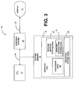
- Fig. 3 is an electronic block diagram of a computer system 16 having the gradient calculation system 10 of the invention implemented in software in a main system memory 18 in connection with a texture mapping system 19 that is also implemented in software (S/W).
- the computer 16 includes a central processing unit (CPU) 17, a main system memory 18 for storing software that is executed by the CPU 17, a graphics system 23 for processing graphics data received from the CPU 17, a local interface 24 configured to electrically interconnect the foregoing elements, and a display 21 (e.g. , a computer monitor) connected to the graphics system 23 via a connection 22 and configured to display the image data generated by the graphics system 23.
- CPU central processing unit
- main system memory 18 for storing software that is executed by the CPU 17
- graphics system 23 for processing graphics data received from the CPU 17
- a local interface 24 configured to electrically interconnect the foregoing elements
- a display 21 e.g. , a computer monitor
- the main system memory 18 includes graphics software 19 as well as any suitable operating system 26.
- the graphics software 19 includes a rasterizer 25 that operates in association with a texture mapping system 27 in order to convert primitive data into pixel data for the display 21.
- the gradient calculation system 10 of the invention is configured to compute precise gradients for the texture mapping system 27 so that appropriate MIP maps 14 (Fig. 2) are selected for pixels 13 in the image data.
- spatial perspective correction may be employed.
- This feature uses the spatial homogeneous coordinate w to correct the user selected x and y coordinates.
- a completely orthogonal concept to this is to add a texture homogeneous coordinate q to the primitive which provides a special effect such as adding a shape to a light shining on a cone.
- the special effect coordinate q is provided from a user either via a texture orientation matrix or as a per vertex coordinate.
- the software-based rasterizer 25 is responsible for sending s/w,t/w, q/w to the texture mapping system 27 for the first pixel in each of the spans 12 (Fig. 1) that the texture mapping system 27 processes.
- the rasterizer 25 linearly interpolates these values along the edge of the primitive 11 (Fig. 1).
- the texture mapping system 27 will interpolate the values along the span 12 and will use s/q, t/q as texture map indices. However, when determining the gradient at a pixel 13 (Fig. 1), rather than using linear approximation, the gradient calculation system 10 of the invention uses an exact closed form equation for the gradient.
- the rasterizer 25 is configured to perform the calculation of s/w, t/w, q/w for the first pixel 13 to be processed in each span 12. The rasterizer 25 will also perform the calculation once per primitive 11.
- the texture mapping system 10 is configured to perform the calculation of s/w, t/w, q/w for each pixel 13 within a span 12, after the first pixel 13. It is also configured to calculate the texel gradient once for each pixel 13 and divide s/w by q/w, and t/w by q/w to get the associated texture map indices once for each pixel 13.
- the texture map indices for each pixel 13 in the primitive 11 and the gradient at each pixel 13 both need to be computed by the texture mapping system 19.
- a mathematical derivation for a general case which covers all cases is set forth hereafter. Note that at least the following cases are covered by the derivation: (1) a non-spatially perspective corrected primitive 11 with or without the texture homogeneous effect, and (2) a spatially perspected primitive with or without the texture homogeneous effect.
- substitute w 1 in the following equations.
- this design uses the fact that for a triangular primitive 11 the variables s p ,t p ,q p are linear with respect to x p and also linear with respect to y p .
- the Equations 1.1, 1.3, 1.5 below prove that this is correct.
- t p (x p ,y p ) t p0 - (x p - x p0 ) b px b pt - (y p - y p0 ) b yp b tp
- b tp (x 2 - x 0 )(y 2 - y 0 ) + (x 1 - x 0 )(y 2 - y 0 ) ⁇ 0
- v 01 (x p1 - x p0 ) x p + (y p1 + y p0 )
- the x screen coordinate is x p and the y screen coordinate is y p .
- Equation 1.0 and Equation 1.3 reflect the values for s p and t p at any point in the primitive 11. Further, using equations 2.0 and 2.1 we note are constant for the entire primitive 11. So, as an optimization feature, the derivatives for these variables need to be calculated just once per primitive 11.
- the gradient ⁇ the derivatives of the true texture indices are calculated.
- the gradient ⁇ max( ⁇ ux , ⁇ uy , ⁇ vx , ⁇ vy ) where u and x are scaled texture coordinates (width and height, respectively) that are scaled to the base MIP map level and where (using the chain rule from calculus): and similarly, where textureWidth and textureHeight are the width and height of the base texture level.
- equation 3.0 shows that is not.
- the gradient will also include the derivative of Note the following: (a) the maximum function (which is our current estimate for the gradient) is an example of a function that is non-differentiable, so it does not make sense to interpolate it to find the derivatives of the gradient; (b) the gradient is nonlinear and also the x derivatives of the derivatives (the second derivative w/r to x and the mixed derivative for y) for the texture indices for homogeneous texture effect are also not linear across the span for the primitive; (c) for a line, the derivatives can be found just using the end points of a line; the interpolation for the texture indices is the same as was for the triangular primitive 11, namely, along the edge of the line; (d) for a point, the gradient turns out to be 1, so set all of the derivative, to zero and set to one.
- the maximum function which is our current estimate for the gradient
- the gradient is nonlinear and also the x derivatives of the derivatives (the second derivative w/r to x
- Fig. 4 shows a flow chart that sets forth not only the operation of the gradient calculation system 10, but also the architecture and functionality of the software-based system 10.
- the blocks of the flowchart can be viewed as sections of code.
- each pixel 13 (Fig. 1) along each span 12 (Fig. 1) of a primitive 11 (Fig. 1) is analyzed, and then a MIP map 14 (Fig. 2) is selected for the pixel 13 at issue.
- the invention further provides an optimization feature that permits the gradient solution to be applied to, preferably, all pixels 13 of a primitive 11, or secondarily, to all subsequent pixels 13 of a span 12, when appropriate.
- rasterizer 25 Prior to operation by the texture mapping system 10, rasterizer 25 (Fig. 3) computes for the primitive 11 using the equations above, which were set forth previously. Furthermore, the rasterizer 25 computes the s p /W, t p /W, q p /W for the first pixel 12 of each span 12 within the primitive 11. To accomplish this, the rasterizer 25 either uses the formulas using linear interpolation along the edge, just as with green, blue, red, or the depth dimension z or uses Equation 1.1, 1.3 and 1.5, as set forth above. The foregoing information will be used by the texture mapping system 27
- the texture mapping system 27 begins processing spans 12 of the primitive 11.
- a loop comprising blocks 31-33 ensures that all spans 12 of the primitive 11 are considered and processed.
- a determination is made as to whether any more spans 12 remain to be processed by the texture mapping system 27. When all the spans have been processed, the texture mapping system 27 concludes. If spans 12 remain to be processed, then block 31 transfers to block 32.
- Block 32 steps along the edge of the primitive 11 to identify the next span 12 for analysis. Block 32 transfers to block 33.
- Block 33 a loop is entered to ensure that all pixels along a span are considered and processed. Block 33 makes an inquiry as to whether any more pixels 13 remain to be processed. If not, then block 33 transfers back to block 31, where another span 12 is retrieved. If, at block 33, more pixels remain to be processed along the span 12, then block 33 transfers to block 34.
- Block 34 steps along the span 12 to the next pixel 13. Block 34 transfers to gradient calculation system 10 of the invention.
- the gradient calculation system 10 now computes the gradients for the present pixel 13 using an exact closed form solution for the partial derivatives. It utilizes the primitive and span information from the rasterizer 25. Furthermore, in the equations that are set forth hereafter, the gradient calculation system 10 uses the MIP map 14 that was selected for the previous pixel as a reference. At this point, the system 10 computes:
- the coordinates u, v define a location within an unnormalized integer coordinate system that corresponds to the normalized s, t coordinate system.
- the texture mapping system 19 determines which MIP map 14 is appropriate based upon the level ⁇ . If ⁇ is a constant that is near zero within a predefined range, then the appropriate MIP map for this pixel 13 is the one that is currently being analyzed. If ⁇ is less than a constant, then the MIP map should be larger (less resolution) and a magnify filter is utilized to generate the appropriate MIP map 14. Further, if ⁇ is a constant and is outside the predefined range, then the MIP map should be reduced (greater resolution) and a minify filter is utilized for this purpose.
- the texture mapping system 27 is configured to apply the gradient solution to, preferably, all remaining pixels 13 of the primitive 11 if this is the first pixel of the primitive 11 and if certain criteria are met. If this short cut cannot be taken, then the texture mapping system 27 can be further configured to determine whether or not a short cut can be taken with respect to the remainder of the span 12 that is at issue. In this regard, the texture mapping system 27 is configured to apply the gradient solution to all subsequent pixels 13 of the span 12, when appropriate based upon another set of criteria.
- the texture mapping system 27 is configured to compute and analyze ⁇ Q/ ⁇ x and ⁇ Q/ ⁇ y. Moreover, if both of the foregoing quantities ⁇ Q/ ⁇ x and ⁇ Q/ ⁇ y are equal to zero, then the texture mapping system 27 can be designed to assign the current MIP map 14 to all remaining pixels 13 of the primitive 11. Alternatively, the texture mapping system 27 may be designed to assign the current MIP map 14 to all subsequent pixels 13 of the current span 12 of the primitive 11 when ⁇ Q/ ⁇ x and ⁇ Q/ ⁇ y are both zero at the present pixel 13.
- the design choice between the former scheme and the latter scheme should be based upon a balancing between accuracy and performance. In other words, the former is faster than the latter, but is less accurate than the latter. The latter design has been adopted in the preferred embodiment in order to achieve higher performance with only a slight compromise in accuracy.
- process control reverts back to block 33 for retrieving another pixel 13, if any remain to be processed, situated either within the current span 12 or on the next span 12, and the foregoing processing steps are reiterated.
- the MIP map 14 that was identified for the previous pixel 13 is utilized and analyzed, at least initially, and it could be magnified or minified, depending upon the calculations for the next pixel 13.
- FIG. 5 A second embodiment of the invention is set forth in Figs. 5 and 6 and generally denoted by reference number 46.
- the texture mapping system 27, as well as the gradient calculation system 10 are implemented in hardware (H/W) within the hardware-based graphics system 23.
- the texture mapping system 27 and gradient calculation system 10 generally exhibit the same architecture, functionality, and operation as their software counterparts that were described previously with respect to Fig. 4.
- FIG. 6 A lower level electronic block diagram that more specifically illustrates the architecture of the hardware-based graphics system 23 is shown in Fig. 6.
- the computer graphics system 23 includes one or more geometry accelerators 42 that are configured to receive vertex data from the CPU 12 and to define the primitives 11 that make up the view to be displayed.
- Each geometry accelerator 42 comprises a number of the specialty control units 43 for processing the image data, including, for example, a transform mechanism (TRANS) 44 for performing transformations on the vertex data, such as scaling or moving a vertex in space, a clip mechanism (CLIP) 46 for clipping portions of objects that extend beyond a boundary, a light mechanism (LIGHT) 48 for enhancing the image data by simulating light conditions, and a plane equation mechanism (PLANE) 52 for defining the primitives in terms of mathematical floating point plane equations.
- TRANS transform mechanism
- CLIP clip mechanism
- LIGHT light mechanism
- PLANE plane equation mechanism
- Each of the control units 43 is typically implemented via cell logic and as separate distinct state machines.
- the output of the geometry accelerator 42 referred to as rendering data, is used to generate final screen coordinates and color data for each pixel and each primitive.
- the output 53 is passed to a rasterizer 25, which converts the geometry accelerator output 53 to fixed point format from floating point format and which produces pixel data 57.
- the gradient calculation system 10 of the invention determines the gradients and assigns the MIP map(s) 14 to the pixels 13.
- the pixel data 57 from the rasterizer 25 is next communicated to a frame buffer control 58 and then to a frame buffer 62.
- the frame buffer 62 serves to temporarily store the pixel data prior to communication to the display 21.
- the pixel data is passed from the frame buffer 62 through a digital-to-analog converter (DAC) 64 and then to the display 21.
- DAC digital-to-analog converter
Landscapes
- Physics & Mathematics (AREA)
- General Physics & Mathematics (AREA)
- Engineering & Computer Science (AREA)
- Theoretical Computer Science (AREA)
- Image Generation (AREA)
Abstract
Description
Using Equation 1.1, take the derivative of sp with respect to the x screen coordinate, and also with respect to the y screen coordinate:


Claims (10)
- A system for accurately establishing texture resolution in a texture mapping system (27) associated with a computer graphics system (18, 23), comprising:a plurality (14) of MIP maps (14a - 14d) with different texel resolutions;gradient calculation logic (10) configured to compute a mathematical closed form solution for texel gradients of one of said MIP maps (14a - 14d) relative to a pixel (13); andMIP map selection logic (27) configured to select an appropriate MIP map (14a - 14d) for said pixel (13) from said plurality (14) of MIP maps (14a - 14d) based upon said gradients.
- The system of claim 1, wherein said gradient calculation logic (10) is configured to compute first and second texel (15) gradients
- The system of claim 1, further comprising logic (38) configured to assign said appropriate MIP map (14a - 14d) to subsequent pixels (13) of a span (12) of said primitive (11) when dQ/dx and dQ/dy are zero at said pixel (13).
- The system of claim 1, further comprising logic (38) configured to assign said appropriate MIP map (14a - 14d) to subsequent pixels (13) of said primitive (11) when ∂Q/∂x and ∂Q/∂y are zero at said pixel (13).
- The system of claim 1, wherein said gradient calculation logic (10) and said MIP map selection logic (27) are implemented in hardware (23) in a rasterizer (25) of said computer graphics system (18, 23).
- The system of claim 1, wherein said gradient calculation logic (10) and said MIP map selection logic (27) are implemented in software (18) that is stored in memory and executed by a processor (17) that is interfaced with said computer graphics system (18, 23).
- The system of claim 2, wherein said MIP map selection logic (27) further comprises:logic (38) configured to scale said gradients to each MIP map (14a - 14b) as follows:logic (38) configured to compute a level λ for each MIP map (14a - 14d) as follows:logic configured to select said appropriate MIP map (14a - 14d)for said pixel (13) from said plurality (14) of MIP maps (14a - 14d) based upon said level λ.
- A system for accurately establishing texture resolution in a texture mapping system (27) associated with a computer graphics system (18, 23), comprising:a plurality (14) of MIP maps (14a - 14d) with different texel (15) resolutions;gradient calculation means (10) for computing first and second texel (15) gradientsMIP map selection means (27) for selecting an appropriate MIP map (14a - 14d) for said pixel (13) from said plurality (14) of MIP maps (14a - 14d) based upon said gradients.
- A method for accurately establishing texture resolution in a texture mapping system (27) associated with a computer graphics system (18, 23), comprising the steps of:providing a plurality (14) of MIP maps (14a - 14d) with different texel resolutions;computing a mathematical closed form solution for texel gradients of one of said MIP maps (14a - 14d) relative to a pixel (13); andselecting an appropriate MIP map (14a - 14d) for said pixel (13) from said plurality (14) of MIP maps (14a - 14d) based upon said gradients.
- The method of claim 9, further comprising the step of assigning said appropriate MIP map (14a - 14d) to subsequent pixels (13) of a span (12) of said primitive (11) when dQ/dx and dQ/dy are zero at said pixel (13).
Applications Claiming Priority (2)
| Application Number | Priority Date | Filing Date | Title |
|---|---|---|---|
| US08/846,744 US6005583A (en) | 1997-04-30 | 1997-04-30 | Precise gradient calculation system and method for a texture mapping system of a computer graphics system |
| US846744 | 1997-04-30 |
Publications (3)
| Publication Number | Publication Date |
|---|---|
| EP0875860A2 true EP0875860A2 (en) | 1998-11-04 |
| EP0875860A3 EP0875860A3 (en) | 1999-03-31 |
| EP0875860B1 EP0875860B1 (en) | 2002-11-06 |
Family
ID=25298822
Family Applications (1)
| Application Number | Title | Priority Date | Filing Date |
|---|---|---|---|
| EP97121694A Expired - Lifetime EP0875860B1 (en) | 1997-04-30 | 1997-12-09 | Precise gradient calculation system and method for a texture mapping system of a computer graphics system |
Country Status (3)
| Country | Link |
|---|---|
| US (1) | US6005583A (en) |
| EP (1) | EP0875860B1 (en) |
| DE (1) | DE69716877T2 (en) |
Cited By (1)
| Publication number | Priority date | Publication date | Assignee | Title |
|---|---|---|---|---|
| WO2002045026A1 (en) * | 2000-12-01 | 2002-06-06 | Stmicroelectronics Sa | Digital image processing method and device |
Families Citing this family (39)
| Publication number | Priority date | Publication date | Assignee | Title |
|---|---|---|---|---|
| JP3179392B2 (en) * | 1997-11-17 | 2001-06-25 | 日本電気アイシーマイコンシステム株式会社 | Image processing apparatus and image processing method |
| US20020002039A1 (en) * | 1998-06-12 | 2002-01-03 | Safi Qureshey | Network-enabled audio device |
| JP4042204B2 (en) * | 1998-04-21 | 2008-02-06 | ソニー株式会社 | Graphic operation apparatus and method |
| US6650327B1 (en) * | 1998-06-16 | 2003-11-18 | Silicon Graphics, Inc. | Display system having floating point rasterization and floating point framebuffering |
| US6469700B1 (en) * | 1998-06-24 | 2002-10-22 | Micron Technology, Inc. | Per pixel MIP mapping and trilinear filtering using scanline gradients for selecting appropriate texture maps |
| US6476816B1 (en) | 1998-07-17 | 2002-11-05 | 3Dlabs Inc. Ltd. | Multi-processor graphics accelerator |
| US7518616B1 (en) * | 1998-07-17 | 2009-04-14 | 3Dlabs, Inc. Ltd. | Graphics processor with texture memory allocation system |
| US6717577B1 (en) | 1999-10-28 | 2004-04-06 | Nintendo Co., Ltd. | Vertex cache for 3D computer graphics |
| US6618048B1 (en) | 1999-10-28 | 2003-09-09 | Nintendo Co., Ltd. | 3D graphics rendering system for performing Z value clamping in near-Z range to maximize scene resolution of visually important Z components |
| US7119813B1 (en) | 2000-06-02 | 2006-10-10 | Nintendo Co., Ltd. | Variable bit field encoding |
| US6486887B1 (en) * | 2000-06-08 | 2002-11-26 | Broadcom Corporation | Method and system for improving color quality of three-dimensional rendered images |
| JP4474743B2 (en) * | 2000-07-03 | 2010-06-09 | ソニー株式会社 | 3D image generating apparatus, 3D image generating method, and program recording medium |
| US7184059B1 (en) | 2000-08-23 | 2007-02-27 | Nintendo Co., Ltd. | Graphics system with copy out conversions between embedded frame buffer and main memory |
| US6636214B1 (en) | 2000-08-23 | 2003-10-21 | Nintendo Co., Ltd. | Method and apparatus for dynamically reconfiguring the order of hidden surface processing based on rendering mode |
| US6980218B1 (en) | 2000-08-23 | 2005-12-27 | Nintendo Co., Ltd. | Method and apparatus for efficient generation of texture coordinate displacements for implementing emboss-style bump mapping in a graphics rendering system |
| US7002591B1 (en) | 2000-08-23 | 2006-02-21 | Nintendo Co., Ltd. | Method and apparatus for interleaved processing of direct and indirect texture coordinates in a graphics system |
| US6937245B1 (en) | 2000-08-23 | 2005-08-30 | Nintendo Co., Ltd. | Graphics system with embedded frame buffer having reconfigurable pixel formats |
| US6707458B1 (en) | 2000-08-23 | 2004-03-16 | Nintendo Co., Ltd. | Method and apparatus for texture tiling in a graphics system |
| US7538772B1 (en) | 2000-08-23 | 2009-05-26 | Nintendo Co., Ltd. | Graphics processing system with enhanced memory controller |
| US6811489B1 (en) | 2000-08-23 | 2004-11-02 | Nintendo Co., Ltd. | Controller interface for a graphics system |
| US6867781B1 (en) | 2000-08-23 | 2005-03-15 | Nintendo Co., Ltd. | Graphics pipeline token synchronization |
| US6700586B1 (en) | 2000-08-23 | 2004-03-02 | Nintendo Co., Ltd. | Low cost graphics with stitching processing hardware support for skeletal animation |
| US7576748B2 (en) | 2000-11-28 | 2009-08-18 | Nintendo Co. Ltd. | Graphics system with embedded frame butter having reconfigurable pixel formats |
| US7034828B1 (en) | 2000-08-23 | 2006-04-25 | Nintendo Co., Ltd. | Recirculating shade tree blender for a graphics system |
| US7196710B1 (en) | 2000-08-23 | 2007-03-27 | Nintendo Co., Ltd. | Method and apparatus for buffering graphics data in a graphics system |
| US7061502B1 (en) | 2000-08-23 | 2006-06-13 | Nintendo Co., Ltd. | Method and apparatus for providing logical combination of N alpha operations within a graphics system |
| US6825851B1 (en) | 2000-08-23 | 2004-11-30 | Nintendo Co., Ltd. | Method and apparatus for environment-mapped bump-mapping in a graphics system |
| US6744442B1 (en) | 2000-08-29 | 2004-06-01 | Harris Corporation | Texture mapping system used for creating three-dimensional urban models |
| US7136069B1 (en) | 2000-10-31 | 2006-11-14 | Sony Corporation | Method and system for texturing |
| US6894696B2 (en) | 2001-12-21 | 2005-05-17 | Sony Corporation | Method and apparatus for providing refractive transparency in selected areas of video displays |
| US7466319B1 (en) | 2002-01-08 | 2008-12-16 | 3Dlabs | System and method for fast gradient pixel clears in graphics rendering |
| US6891548B2 (en) * | 2002-08-23 | 2005-05-10 | Hewlett-Packard Development Company, L.P. | System and method for calculating a texture-mapping gradient |
| US7525543B2 (en) * | 2004-08-09 | 2009-04-28 | Siemens Medical Solutions Usa, Inc. | High performance shading of large volumetric data using screen-space partial derivatives |
| US8300059B2 (en) * | 2006-02-03 | 2012-10-30 | Ati Technologies Ulc | Method and apparatus for selecting a mip map level based on a min-axis value for texture mapping |
| KR100745768B1 (en) * | 2006-08-29 | 2007-08-02 | 삼성전자주식회사 | Calculation method of LOD value to reduce power consumption and 3D rendering system using it |
| US12154028B2 (en) * | 2017-05-05 | 2024-11-26 | Intel Corporation | Fine-grain compute communication execution for deep learning frameworks via hardware accelerated point-to-point primitives |
| CN111553969B (en) * | 2019-12-31 | 2023-09-05 | 深圳积木易搭科技技术有限公司 | A Gradient Field-Based Texture Mapping Method, Medium, Terminal and Device |
| US11182159B2 (en) | 2020-02-26 | 2021-11-23 | Google Llc | Vector reductions using shared scratchpad memory |
| CN113392858B (en) * | 2020-12-08 | 2025-06-24 | 腾讯科技(深圳)有限公司 | Image data processing method, computer device and medium |
Family Cites Families (5)
| Publication number | Priority date | Publication date | Assignee | Title |
|---|---|---|---|---|
| US5224208A (en) * | 1990-03-16 | 1993-06-29 | Hewlett-Packard Company | Gradient calculation for texture mapping |
| US5490240A (en) * | 1993-07-09 | 1996-02-06 | Silicon Graphics, Inc. | System and method of generating interactive computer graphic images incorporating three dimensional textures |
| JPH08249491A (en) * | 1995-02-14 | 1996-09-27 | Internatl Business Mach Corp <Ibm> | 3-d graphic device using texture image containing depth information |
| US5719599A (en) * | 1995-06-07 | 1998-02-17 | Seiko Epson Corporation | Method and apparatus for efficient digital modeling and texture mapping |
| US5719600A (en) * | 1995-12-12 | 1998-02-17 | Hewlett-Packard Company | Gradient calculation system and method |
-
1997
- 1997-04-30 US US08/846,744 patent/US6005583A/en not_active Expired - Lifetime
- 1997-12-09 EP EP97121694A patent/EP0875860B1/en not_active Expired - Lifetime
- 1997-12-09 DE DE69716877T patent/DE69716877T2/en not_active Expired - Lifetime
Cited By (3)
| Publication number | Priority date | Publication date | Assignee | Title |
|---|---|---|---|---|
| WO2002045026A1 (en) * | 2000-12-01 | 2002-06-06 | Stmicroelectronics Sa | Digital image processing method and device |
| FR2817641A1 (en) * | 2000-12-01 | 2002-06-07 | St Microelectronics Sa | METHOD AND DEVICE FOR PROCESSING DIGITAL IMAGES |
| US7447349B2 (en) | 2000-12-01 | 2008-11-04 | Stmicroelectronics Sa | Method and a system for processing digital images |
Also Published As
| Publication number | Publication date |
|---|---|
| DE69716877D1 (en) | 2002-12-12 |
| US6005583A (en) | 1999-12-21 |
| EP0875860A3 (en) | 1999-03-31 |
| DE69716877T2 (en) | 2003-09-18 |
| EP0875860B1 (en) | 2002-11-06 |
Similar Documents
| Publication | Publication Date | Title |
|---|---|---|
| EP0875860B1 (en) | Precise gradient calculation system and method for a texture mapping system of a computer graphics system | |
| US7081895B2 (en) | Systems and methods of multi-pass data processing | |
| US11600044B2 (en) | Rendering textures utilizing sharpness maps | |
| US6563501B2 (en) | Bicubic surface rendering | |
| KR101033779B1 (en) | Method and apparatus for processing an image using a graphics processing unit having an extended vertex cache | |
| US6359619B1 (en) | Method and apparatus for multi-phase rendering | |
| US6532013B1 (en) | System, method and article of manufacture for pixel shaders for programmable shading | |
| US8059119B2 (en) | Method for detecting border tiles or border pixels of a primitive for tile-based rendering | |
| US20050068333A1 (en) | Image processing apparatus and method of same | |
| US10593096B2 (en) | Graphics processing employing cube map texturing | |
| US7295204B2 (en) | Rapid zippering for real time tesselation of bicubic surfaces | |
| US11593992B2 (en) | Rendering three-dimensional objects utilizing sharp tessellation | |
| EP1519317B1 (en) | Depth-based antialiasing | |
| CN101714259B (en) | Graphics processing systems | |
| US6100898A (en) | System and method of selecting level of detail in texture mapping | |
| US20100110093A1 (en) | Graphics processing systems | |
| US7525553B2 (en) | Computer graphics processor and method for generating a computer graphics image | |
| US7256792B1 (en) | Method and apparatus for sampling non-power of two dimension texture maps | |
| JP2006517705A (en) | Computer graphics system and computer graphic image rendering method | |
| Hormann et al. | A quadrilateral rendering primitive | |
| US7280108B2 (en) | Bicubic surface rendering | |
| US6570575B1 (en) | Associated color texture processor for high fidelity 3-D graphics rendering | |
| US20030189570A1 (en) | Bicubic surface rendering | |
| Ivanov et al. | Spatial Patches‐A Primitive for 3D Model Representation | |
| EP1766584A2 (en) | Inverse texture mapping 3d graphics system |
Legal Events
| Date | Code | Title | Description |
|---|---|---|---|
| PUAI | Public reference made under article 153(3) epc to a published international application that has entered the european phase |
Free format text: ORIGINAL CODE: 0009012 |
|
| AK | Designated contracting states |
Kind code of ref document: A2 Designated state(s): DE FR GB |
|
| AX | Request for extension of the european patent |
Free format text: AL;LT;LV;MK;RO;SI |
|
| PUAL | Search report despatched |
Free format text: ORIGINAL CODE: 0009013 |
|
| AK | Designated contracting states |
Kind code of ref document: A3 Designated state(s): AT BE CH DE DK ES FI FR GB GR IE IT LI LU MC NL PT SE |
|
| AX | Request for extension of the european patent |
Free format text: AL;LT;LV;MK;RO;SI |
|
| 17P | Request for examination filed |
Effective date: 19990706 |
|
| AKX | Designation fees paid |
Free format text: DE FR GB |
|
| RAP1 | Party data changed (applicant data changed or rights of an application transferred) |
Owner name: HEWLETT-PACKARD COMPANY, A DELAWARE CORPORATION |
|
| GRAG | Despatch of communication of intention to grant |
Free format text: ORIGINAL CODE: EPIDOS AGRA |
|
| 17Q | First examination report despatched |
Effective date: 20020313 |
|
| GRAG | Despatch of communication of intention to grant |
Free format text: ORIGINAL CODE: EPIDOS AGRA |
|
| GRAH | Despatch of communication of intention to grant a patent |
Free format text: ORIGINAL CODE: EPIDOS IGRA |
|
| GRAH | Despatch of communication of intention to grant a patent |
Free format text: ORIGINAL CODE: EPIDOS IGRA |
|
| GRAA | (expected) grant |
Free format text: ORIGINAL CODE: 0009210 |
|
| AK | Designated contracting states |
Kind code of ref document: B1 Designated state(s): DE FR GB |
|
| REG | Reference to a national code |
Ref country code: GB Ref legal event code: FG4D |
|
| REF | Corresponds to: |
Ref document number: 69716877 Country of ref document: DE Date of ref document: 20021212 |
|
| ET | Fr: translation filed | ||
| PLBE | No opposition filed within time limit |
Free format text: ORIGINAL CODE: 0009261 |
|
| STAA | Information on the status of an ep patent application or granted ep patent |
Free format text: STATUS: NO OPPOSITION FILED WITHIN TIME LIMIT |
|
| 26N | No opposition filed |
Effective date: 20030807 |
|
| REG | Reference to a national code |
Ref country code: GB Ref legal event code: 732E Free format text: REGISTERED BETWEEN 20120329 AND 20120404 |
|
| REG | Reference to a national code |
Ref country code: FR Ref legal event code: PLFP Year of fee payment: 19 |
|
| PGFP | Annual fee paid to national office [announced via postgrant information from national office to epo] |
Ref country code: GB Payment date: 20151125 Year of fee payment: 19 Ref country code: DE Payment date: 20151119 Year of fee payment: 19 |
|
| PGFP | Annual fee paid to national office [announced via postgrant information from national office to epo] |
Ref country code: FR Payment date: 20151123 Year of fee payment: 19 |
|
| REG | Reference to a national code |
Ref country code: DE Ref legal event code: R119 Ref document number: 69716877 Country of ref document: DE |
|
| GBPC | Gb: european patent ceased through non-payment of renewal fee |
Effective date: 20161209 |
|
| REG | Reference to a national code |
Ref country code: FR Ref legal event code: ST Effective date: 20170831 |
|
| PG25 | Lapsed in a contracting state [announced via postgrant information from national office to epo] |
Ref country code: FR Free format text: LAPSE BECAUSE OF NON-PAYMENT OF DUE FEES Effective date: 20170102 |
|
| PG25 | Lapsed in a contracting state [announced via postgrant information from national office to epo] |
Ref country code: GB Free format text: LAPSE BECAUSE OF NON-PAYMENT OF DUE FEES Effective date: 20161209 Ref country code: DE Free format text: LAPSE BECAUSE OF NON-PAYMENT OF DUE FEES Effective date: 20170701 |