US7136069B1 - Method and system for texturing - Google Patents
Method and system for texturing Download PDFInfo
- Publication number
- US7136069B1 US7136069B1 US09/703,020 US70302000A US7136069B1 US 7136069 B1 US7136069 B1 US 7136069B1 US 70302000 A US70302000 A US 70302000A US 7136069 B1 US7136069 B1 US 7136069B1
- Authority
- US
- United States
- Prior art keywords
- texture
- texel
- alpha
- values
- texturing
- Prior art date
- Legal status (The legal status is an assumption and is not a legal conclusion. Google has not performed a legal analysis and makes no representation as to the accuracy of the status listed.)
- Expired - Lifetime, expires
Links
Images


Classifications
-
- G—PHYSICS
- G06—COMPUTING; CALCULATING OR COUNTING
- G06T—IMAGE DATA PROCESSING OR GENERATION, IN GENERAL
- G06T15/00—3D [Three Dimensional] image rendering
- G06T15/04—Texture mapping
Definitions
- the present invention relates to generating graphics. Specifically, the present invention relates to a method and system for texturing.
- existing texture-rendering techniques map a pixel on a screen (typically using screen coordinates (x, y)) to a polygon, such as a triangle, on a surface in a viewing plane (typically using geometric or surface coordinates (s, t)).
- the polygon is rasterized into a plurality of smaller pieces called fragments.
- Each polygon may have information, such as color and/or a normal vector, associated with each vertex of the polygon.
- a texture i.e., a color pattern or image, either digitized or synthesized
- the fragment is mapped onto a texture map (typically using texture coordinates (u, v)). Texture maps are stored in a texture memory.
- a texture map represents a type of image, such as stripes, check.erboards, or complex patterns that characterize natural materials.
- a texture map comprises a plurality of texels.
- a texel is the smallest graphical element in a 2-D texture map used to render a 3-D object.
- Each texture map has a plurality of associated MIP (multum in parvo) maps, which are abbreviated versions of a full texture map.
- MIP maps may be selected to provide a suitable resolution for the fragment of the polygon in the viewing plane.
- the texture from the selected MIP map is applied onto the fragment.
- the applied texture may be blended with a color already associated with the fragment or polygon.
- Existing texture-rendering techniques are able to model a simple opaque surface, but are unable to accurately render a semi-opaque surface, where the upper layers of the surface are partially transparent, and reveal sub-surface details.
- a semi-opaque surface is not transparent in that an object behind the surface will not show through it.
- the transparency of a semi-opaque surface applies to the upper layers of the surface, as the upper layers allow details from the lower surface layers to appear.
- multi-texturing Another problem with conventional texturing systems is the need to make multiple passes in order to apply multiple textures to a fragment, which is called ‘multi-texturing.’
- Conventional texturing systems can only access and read one texture image (a MIP map set) at a time.
- conventional texturing systems must make multiple passes, i.e., read a first texture image, then a second texture image, then a third texture image, etc.
- conventional systems typically separate the texel data into individual components and combine the color components from each texture image to produce a blended color to apply to a fragment.
- the present invention relates to a method and system for texturing.
- One aspect of the texturing system advantageously allows a hardware- or software-based polygon texturing engine to render surfaces that have an apparent thickness (i.e., surface depth), where the upper layers are partially transparent and sub-surface details at least partially show (i.e., become visible) through the upper layers.
- the present texturing system and method may be used to render an emperor's throne made of opal in a fantasy-based computer game.
- Some types of plastic and thickly-layered metal flake paint also exhibit this semi-opaque surface quality.
- Other layered materials include biological tissues (e.g., skin, leaves, etc.) or inorganic materials (e.g., snow, sand, paint, varnished or dusty surfaces).
- the texturing system advantageously does not require additional polygon modeling or volumetric analysis and calculations to create the appearance of surface depth, as required in existing systems.
- the texturing system advantageously allows multiple textures to be applied in a single pass by a texturing engine.
- the texturing system minimizes the inefficiency of multi-pass rendering associated with conventional systems.
- the texturing system is implemented in a real-time, hardware-based rendering system, such as a graphics-rendering card. In another embodiment, the texturing system is implemented in a software-based rendering system.
- One embodiment of the method for surface depth texturing comprises determining a depth stepping angle, the depth stepping angle formed by a first vector from an eye point position to a fragment in a polygon surface and a second vector normal to the surface of the fragment; converting the depth stepping angle to one or more texel offset values; applying the texel offset values to a first texel in a first texture layer to find a corresponding second texel in a second texture layer; blending one or more color values and one or more alpha values associated with the first and second texels to create an apparent surface depth for the fragment; and applying the blended color values and alpha values to the fragment.
- One embodiment of the surface-depth texturing system comprises a texturing engine and a texturing memory coupled to the texturing engine.
- the texturing engine is configured to retrieve a first texel in a first texture layer from the texture memory; determine a depth stepping angle between a first vector from an eye point position to a fragment in a polygon surface and a second vector normal to the surface of the fragment; convert the depth stepping angle to one or more texel offset values; apply the texel offset values to the first texel to find a corresponding second texel in a second texture layer; blend one or more color values and one or more alpha values associated with the first and second texels to create an apparent surface depth for the fragment; and apply the blended color values and alpha values to the fragment.
- Another aspect of the texturing system provides a novel way of organizing texture memory and the addition of control registers and lookup tables to existing texturing hardware.
- the texture memory format advantageously avoids the inconvenience and delay of memory page swapping in conventional texture memory systems.
- One embodiment of the texturing system comprises a texture memory controller coupled to a texturing engine and a texture memory.
- the texture memory is configured to store texture data as a plurality of packets. Each packet comprises texture data from at least two texture layers.
- the texture memory controller is configured to access one or more packets in the texture memory and pass the packets to the texturing engine.
- One embodiment of a method for managing texture data comprises storing a texture map set in a texture memory, where the texture map set comprising two or more texture layers.
- FIG. 1A illustrates a first eye point position above a plurality of texture layers.
- FIG. 1B illustrates a second eye point position above a plurality of texture layers.
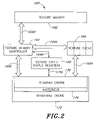
- FIG. 2 illustrates one embodiment of a texturing system in accordance with the present invention.
- FIG. 3 illustrates one embodiment of a texture memory format that may be used by the texturing system of FIG. 2 .
- FIGS. 4A–4D illustrate one embodiment of a texture-packing format applied to multiple MIP levels that may be used by the texturing system of FIG. 2 .
- FIGS. 5A–5C illustrate a depth stepping angle and its components.
- FIGS. 6A–6B illustrate one embodiment of a method of processing texels on multiple texture layers.
- FIG. 7A illustrates another embodiment of a texture memory format that may be used by the texturing system of FIG. 2 .
- FIGS. 7B–7C illustrate two embodiments of alpha maps that may be used by the texturing system of FIG. 2 .
- FIG. 1A illustrates a first eye point position 100 above a plurality of texture layers comprising a first texture layer 102 , a second texture layer 104 , a third texture layer 106 , and a fourth texture layer 108 .
- Each texture layer 102 , 104 , 106 , 108 comprises a texture map with all of its associated MIP (multum in parvo) maps.
- Texture mapping is described in “Computer Graphics Principles and Practice” by James D. Foley et al., 1997, on pages 741–744, and “Introductive Computer Graphics, A top-down approach with OpenGL” by Edward Angel, 1997, pages 389–397, which are hereby incorporated by reference in their entirety.
- MIP mapping is described on pages 826–828 of “Computer Graphics Principles and Practice.”
- FIG. 1A illustrates a first texel 110 in the first texture layer 102 , a second texel 112 in the second texture layer 104 , a third texel 114 in the third texture layer 106 and a fourth texel 116 in a fourth texel layer 108 .
- the first, second, third and fourth texels 110 , 112 , 114 , 116 are associated with an eye point vector 118 .
- an illusion of depth at the first eye point 100 is achieved through blending values that are used to combine the first, second, third and fourth texels 110 , 112 , 114 , 116 chosen from four texture layers 102 , 104 , 106 , 108 and from a parallax created between the different layers 102 , 104 , 106 , 108 .
- Parallax is the apparent change in view as the eye point 100 changes position, which provides a new line of sight.
- FIG. 1B illustrates a second eye point 120 above a plurality of texture layers 102 , 104 , 106 , 108 .
- the illusion of depth at the second eye point position 120 is achieved through blending modes that are used to combine texels 124 , 126 , 128 , 130 chosen from each texture layer 102 , 104 , 106 , 108 and from the parallax between the different layers 102 , 104 , 106 , 108 .
- FIGS. 1 and 2 illustrate how changing the eye point angle for a given texel, such as texel 110 or 125 , in the first texel layer 102 changes the selected texels in lower texel layers.
- the texture layers 102 , 104 , 106 , 108 of FIGS. 1A and 1B may represent opaque surfaces that have layered partial transparency, such as Opal, Aragonite, Pectolite and other minerals and gemstones. Some types of plastic and thickly-layered metal flake paint also exhibit this semi-opaque surface quality. Other layered materials include biological tissues (e.g., skin, leaves, etc.) or inorganic materials (e.g., snow, sand, paint, varnished or dusty surfaces).
- each texel in each texture layer has two parts: a color component and an alpha value ( ⁇ ).
- the alpha value is a blending value associated with a red-green-blue (RGB) triplet.
- the alpha value may be specified per color component (red, green and blue). For example, there may be a first alpha value for red, a second alpha value for green, and a third alpha value for blue.
- the alpha values may allow the color of one texel in one texture layer to tint the colors of a texel in a layer above or below the first layer.
- the alpha values may span a range to allow a color in a layer to span a spectrum from fully opaque to fully clear.
- FIG. 2 illustrates one embodiment of a texturing system 160 in accordance with the present invention.
- the texturing system 160 comprises a texture memory 162 , a texture memory controller 164 , a texture cache 166 , a set of texture cache status registers 168 , a texturing engine 170 , a rasterizer 174 , and a rendering engine 172 .
- FIG. 2 may be implemented by software, hardware or a combination of software and hardware.
- the texture memory 160 may comprise, for example, an EEPROM, DRAM, SDRAM, flash memory or other suitable storage unit.
- the texture cache 166 may comprise, for example, an EEPROM, DRAM, SDRAM, flash memory or other suitable storage unit.
- the texture memory controller 164 may comprise a microcontroller.
- the texture status registers 168 may comprise an array of registers.
- the texturing engine 170 , rasterizer 174 and rendering engine 172 may comprise a microcontroller with firmware and may be separate or integrated components.
- Each line 164 A, 164 B, 164 C, 164 D, 166 A, 170 A may comprise a single line, a plurality of lines, a bus, a combination of single lines and buses, or some other suitable type of address and/or data transfer means.
- FIG. 3 illustrates one embodiment of a texture memory format 140 that may be used by the texture memory 162 of FIG. 2 .
- the texture memory format 140 may represent a texture map set that comprises two or more texture layers.
- the memory format 140 comprises a plurality of rows and columns. Each row of the memory format 140 represents a memory word, such as the first memory word 142 shown in FIG. 3 .
- Each memory word comprises 64 bits or eight bytes, where each byte comprises eight bits.
- Each byte stores color data values, such as red (R), blue (B) or green (G), or ⁇ values.
- each memory word may be 16, 32, 48 or 80 bits wide or some other suitable width.
- each memory word such as the first memory word 142 , comprises color values from the first, second, third and fourth texture layers 102 , 104 , 106 , 108 of FIGS. 1A–1B .
- color values of the first texture layer 102 of FIG. 1A are stored in the first pair of columns 150 of the memory format 140 .
- Color values of the second texture layer 104 of FIG. 1A are stored in the second pair of columns 152 of the memory format 140 .
- Color values of the third texture layer 106 of FIG. 1A are stored in the third pair of columns 154 of the memory format 140 .
- Color values of the fourth texture layer 108 of FIG. 1A are stored in the fourth pair of columns 156 of the memory format 140 .
- Each texel such as the first texel 158 in the first texture layer 102 , comprises an R data value, an R alpha component, a G data value, a G alpha value, a B data value and a B alpha value.
- a ‘texture packet’ or ‘packet’ may refer to a color component packet or a texel packet.
- a color component packet comprises color values associated with one color, such as red, wherein the color values are from two or more texture layers.
- a color component packet may or may not comprise alpha values.
- One example of a color component packet comprises the first memory word 142 in FIG. 3 .
- Another example of a color component packet comprises the first four bytes 362 , 360 , 364 , 366 in FIG. 3 .
- Another example of a color component packet comprises the first word 324 of texture memory format 320 in FIG. 7A .
- Another example of a color component packet comprises the first and second bytes 350 , 400 in FIG. 7A .
- a texel packet comprises one or more texels, wherein in a texel comprises a red color value byte, a green color value byte and a blue color value byte.
- a texel packet may or may not comprise alpha values.
- One example of a texel packet comprises the first texel 158 in FIG. 3 .
- Another example of a texel packet comprises the four texels in the three memory words 144 , 146 , 148 shown in FIG. 3 .
- Another example of a texel packet comprises the RGB triplet 328 in FIG. 7A .
- Another example of a texel packet comprises the packet 322 in FIG. 7A .
- FIGS. 4A–4D illustrate one embodiment of a texture-packing format applied to multiple MIP levels that may be used by the texturing system 160 of FIG. 2 .
- a first level MIP map 180 is eight texels high and eight texels wide and comprises a first layer 182 and a second layer 184 .
- a second level MIP map 190 is four texels high and four texels wide.
- a third level MIP map 192 is two texels high and two texels wide.
- a fourth level MIP map 194 is one texel high and one texel wide.
- the color component packing format of FIG. 3 applies to all of the MIP maps of the stored texture, as shown in FIGS. 4A–4D .
- the size of a fragment to be textured determines which MIP map in FIGS. 4A–4D is used by the texturing engine 170 .
- all of the images used in a layered texture are matched to have the same width and height before being stored as texture MIP map data.
- the texture memory controller 164 of FIG. 2 receives new textures sent by a host computer (not shown) with pre-set attributes for each texture.
- the texture memory controller 164 stores the new textures in the texture memory 162 via line 164 D.
- the textures may be stored as texture map sets, where each texture map set comprises two or more texture layers.
- the pre-set attributes include at least a width, a height, a texel format and a texel packing factor.
- the texel format indicates (i) the number of bits per texel, (ii) a texel operation mode (e.g., true color or color look-up table (CLUT)), and (iii) a texture mode flag to indicate whether depth texturing is to be used or not.
- a texel operation mode e.g., true color or color look-up table (CLUT)
- the texel packing factor can be used to layer several textures together for either (1) depth texturing or for (2) combining several textures in a single rendering pass.
- the difference between (1) and (2) is the depth stepping offset between texture layers in the latter case is set to zero.
- the texture mode flag controls whether a depth stepping offset between textures will be used or not.
- the texture memory controller 164 of FIG. 2 packs color and alpha data values from several texture layers 102 , 104 , 106 , 108 ( FIG. 1A ) together into each memory word, which is stored in the memory format 140 of FIG. 3 or FIGS. 7A–7C .
- four texels from four different texture layers 102 , 104 , 106 , 108 ( FIG. 1A ) are packed into three memory words 144 , 146 , 148 in FIG. 3 .
- the packing arrangement of FIGS. 3 and 4 A– 4 D allows the texture memory controller 164 to access the packed color and alpha data values (texture data) from several texture layers as a discrete packet. Examples of color component packets and texel packets are described above.
- the texture memory controller 164 may then pass one or more packets via line 164 A to the texture cache 166 and/or the texturing engine 170 via line 164 C.
- the packing arrangements of FIGS. 3 , 4 A– 4 D and 7 A– 7 C advantageously improve the speed and efficiency of the texture memory controller 164 and the texturing engine 170 .
- the texture cache 166 stores packets that have been recently accessed by the texture memory controller 164 .
- the texture cache 166 may store texels from multiple textures for a scene, such as textures for a ceiling, a floor and a throne, of a throne room in a game.
- the texture cache 166 passes the packets to the texturing engine 170 via line 166 A, as described below.
- the texture cache status registers 168 receive and store information, such as the texture attributes described above, from the texture memory controller 164 via line 164 B.
- the information from the texture memory controller 164 may indicate which texture is in each cache page, the texture mode and the packing scheme, e.g., the color component packing format used for each texture packet/set.
- a “texture packet request” may comprise (1) a request for one or more RGB texels, including one or more R alpha values, G alpha values and B alpha values, from the same texture layer; (2) a request for one or more RGB texels, including one or more R alpha values, G alpha values and B alpha values, from two or more different texture layers; or (3) a request for a one or more memory words, such as the first memory word 142 shown in FIG. 3 .
- the texture memory controller 164 or the texturing engine 170 accesses the texture cache status registers 168 via lines 164 B or 170 A to determine whether some or all of the requested texture packets are in the texture cache 166 . If some or all of the requested texture packets are in the texture cache 166 , then the texture memory controller 164 or the texturing engine 170 commands the texture cache 166 to pass the requested texture packets in the texture cache 166 to the texturing engine 170 via line 166 A for processing.
- the texturing engine 170 may request texture packets that have been used in a previous rendering process, such as for example, in a multi-texturing or semi-opaque surface rendering process.
- the texture cache 166 provides the requested texture packets to the texturing engine 170 faster than the texture memory controller 164 retrieving the requested texture packets from the texture memory 162 .
- the texture memory controller 164 retrieves the requested texture packets from the texture memory 162 via line 164 D. Various methods of retrieval may be used, such as for example, retrieval by one or more texels or by one or more memory words, as described above with reference to FIGS. 3 and 7 A– 7 C.
- the texture memory controller 164 passes the requested texture packets to the texture cache 166 via line 164 B.
- the texture cache 166 caches the requested texture packets and passes the requested texture packets to the texturing engine 170 via line 166 A.
- the texture memory controller 164 sends an interrupt signal to the texturing engine 170 via line 164 C to indicate when requested texture packets are in the texture cache 166 and ready for retrieval.
- the texturing engine 170 may then send a texture packet request to the texture cache 166 via line 166 A to command the texel cache 166 to begin passing the requested texture packets to the texturing engine 170 .
- the texture memory controller 164 When the texture memory controller 164 retrieves requested texture packets from the texture memory 162 via line 164 D, the texture memory controller 164 also retrieves information about the texture packets, such as the attributes described above, and passes the information to the texture cache status registers 168 via line 164 B.
- the information in the texture cache status registers 168 may indicate which texture is in each cache page, including the texture mode and the packing scheme.
- the information in the texture cache status registers 168 may be accessed by the texture memory controller 164 via line 164 B or the texturing engine 170 via line 170 A.
- FIG. 7A illustrates another embodiment of a texture memory format 320 that may be used by the texturing system 160 of FIG. 2 .
- the format 320 of FIG. 7A allows eight texture layers to be stored and accessed together.
- Each memory word, such as the first word 324 comprises eight color values, where each color value is from a different texture layer.
- a packet, such as the packets 322 , 326 of three memory words contains eight RGB triplets from eight different texture layers.
- the format 320 allows the texture memory controller 164 to access texels from twice as many texture layers at one time as the format 140 in FIG. 3 .
- FIGS. 7B–7C illustrate two embodiments of alpha maps 330 , 340 that may be used in conjunction with the memory format 320 of FIG. 7A by the texturing system 160 of FIG. 2 .
- each alpha value is associated with a RGB triplet in FIG. 7A .
- a first alpha value 332 represents the amount of blending or mixing for a first RGB triplet 328 in FIG. 7A .
- each alpha value is associated with a color value component in FIG. 7A .
- a first alpha value 342 in FIG. 7C is associated with a first color value 350 in FIG. 7A
- a second alpha value 344 is associated with a second color value 352
- a third alpha value 346 is associated with a third color value 354 .
- the texturing engine 170 applies textures to a semi-opaque surface one fragment at a time.
- the texturing of semi-opaque surfaces described herein may be implemented with the memory formats shown in FIGS. 3 , 4 A– 4 D and 7 A– 7 C or other suitable memory configurations known to those skilled in the art.
- the texturing engine 170 of FIG. 2 applies a unique offset between the texture layers to each polygon fragment, such as the polygon fragment 208 shown in FIG. 5A .
- the offset is derived by interpolating two values associated with each vertex of the polygon fragment. These two values comprise a depth stepping angle 212 in the x direction ( FIG. 5B ) and a depth stepping angle 230 in the y direction ( FIG. 5C ) at each vertex of the polygon fragment.
- FIGS. 5A–5C illustrate a depth stepping angle 200 and its components 212 , 230 .
- FIG. 5A further illustrates a fragment 208 on a polygon surface 210 in an (x, y, z) viewing plane, where the texturing engine 170 of FIG. 2 will map texture(s) from the texture memory 160 and/or the texture cache 166 to the fragment 208 .
- the depth stepping angle 200 is the angle between (i) a vector 204 from an eye point 202 to a fragment center 208 ′ on a surface (or polygon) 210 that is being rendered, and (ii) a local surface normal vector 206 at the fragment 208 on the polygon 210 where the texel data is to be mapped.
- the stepping angle 200 is expressed in radians as having an X-component 212 and a Y-component 230 as shown in FIGS. 5B and 5C .
- the texturing engine 170 interpolates the eye point vector 204 for the fragment 208 from eye point vectors associated with vertices 310 , 312 , 314 of the polygon 210 . Likewise, the texturing engine 170 may interpolate the normal vector 206 for the fragment 208 from the vectors associated with vertices 310 , 312 , 314 of the polygon 210 .
- FIG. 5B illustrates the X-component 212 of the depth-stepping angle which comprises an angle between (i) a vector 216 from an eye point 202 to a fragment center 218 ′ on a surface 214 in the X-Z plane, and (ii) a local surface normal vector 220 at the fragment 218 on the polygon 214 in the X-Z plane.
- FIG. 5C illustrates the Y-component 230 of the depth-stepping angle which comprises an angle between (i) a vector 222 from an eye point 202 to a fragment center 226 ′ on a surface 224 in the Y-Z plane, and (ii) a local surface normal vector 228 at the fragment 226 on the polygon 224 in the Y-Z plane.
- the X and Y components 212 , 230 of the depth stepping angle 200 represent X and Y depth stepping values in radians that range from 0.0 to ⁇ /2 (i.e., from 0.0 to 1.5707963 . . . ).
- the system 160 uses floating point numbers, which are expressed in fixed-point representation/notation.
- the texturing engine 170 converts the X and Y depth stepping values to X and Y texel offset values.
- the X and Y texel offset values simply equal the X and Y depth stepping values.
- the texturing engine 170 uses the X and Y texel offset values to determine which texels from each lower texture layer are used to render a particular fragment.
- the texturing engine 170 applies the X and Y offset values to a selected texel(s) in a top texture layer, such as the first texel 110 in the first texture layer 102 in FIG. 1A , to find a corresponding texel(s) in a second layer, such as the second texel 112 in the second texture layer 104 in FIG. 1A .
- the texturing engine 170 then applies the offset values to the texel(s) chosen from the second layer to find a texel(s) in a third layer, such as the third texel 114 in the third texture layer 106 in FIG. 1A .
- the texturing engine 170 then applies the offset values to the texel(s) in the third layer to find a texel(s) in a fourth layer, such as the fourth texel 116 in the fourth texture layer 108 in FIG. 1A . These steps may be repeated thereafter if there are more than four texture layers.
- the texturing engine 170 may use less than four texture layers or more than four texture layers.
- the offset values may be positive or negative, depending on whether the texturing engine 170 selects texels toward or away from the eye point on lower texture layers.
- the amount of parallax or displacement between texels in different texture layers determines the amount of distortion of multiple textures applied to a fragment. Exemplifying distortions include distortion by glass, plastic materials, fog, semi-opaque materials, etc.
- the texturing engine 170 may adjust the amount of parallax based on the desired features of a particular image. If there is no parallax, then the textures are applied to the fragment as conventional multi-texturing with no apparent surface depth.
- the texturing engine 170 uses a left bit shift to control the amount of parallax displacement between texels in different texture layers.
- a left bit shift means binary bits representing a texel offset value are shifted to the left by one.
- the projected fragment is shifted according to the coordinates of the polygon in the viewing plane, not according to the coordinates of the texture map.
- the shift of a projected fragment on a texture map depends on the orientation of the projected fragment onto the texture map.
- the bit shift controls the maximum texel displacement when the angle (e.g., angle 212 ) between the surface normal (e.g., normal 220 ) and the eye point vector (e.g., vector 216 ) reaches 90 degrees.
- the maximum shift between layers is approximately 1.5707963 texels.
- the maximum shift between layers becomes approximately 3.141529 texels.
- the bit shift factor increases, the maximum shift between multiple texture layers increases.
- Changing the shift factor allows for control of the amount of parallax between texture layers, such as the texture layers 102 , 104 , 106 , 108 of FIG. 1A . As an object is moved or rotated, the parallax between these layers will give the illusion of depth to the surface.
- the texturing engine 170 may use another adjustment to scale the texel offset values to a particular MIP level used for texturing. As described above, the texturing engine 170 selects a MIP map based on the size of the projected fragment into texture space. For the first MIP level, there is no adjustment to the texel offset values. For the second MIP level, the adjustment may be accomplished by right-shifting the texel offset values by one. For the third MIP level, the adjustment may be accomplished by right-shifting the texel offset values by two. For the fourth MIP level, the adjustment may be accomplished by right-shifting the texel offset values by three.
- the texturing engine 170 may use signed incremental addition to increment the Y-depth stepping angle 230 for each new span (contiguous group of pixels of a polygon) and to set the starting X-depth stepping angle 212 at the beginning of each span. While the texturing engine 170 renders a span, the X-depth stepping angle 212 is incremented for each fragment 208 . This process is comparable to interpolating surface normal values across the face of a polygon 210 . The difference is, here the texturing engine 170 is interpolating the angle 200 between the eye point 202 and the surface normal 206 for the fragment 208 being rendered.
- the alpha components in a particular texture layer may determine how much of the texture layers below the particular layer shows through.
- the color components in each texture layer are blended to create the surface and sub-surface details that create the “look” of a texture at a fragment.
- the first red alpha value 360 determines whether the first red value 362 is opaque or transparent or somewhere in between.
- the first alpha value 360 can be said to control the blending between the first and second red color values 362 , 364 .
- the alpha values for the lowest texture layer 156 control the blending of the depth texture(s) with an interpolated polygon color at the location of the fragment being textured.
- the depth texture(s) may comprise either (1) a combined color texture of the first, second and third color values 362 , 364 , 368 , 372 and their alpha values 360 , 366 , 370 or (2) the color value 372 of the last texture layer 156 .
- the polygon color at a fragment location is interpolated from the color values associated with each vertex of the polygon and the location of the fragment within the polygon.
- the alpha values of the last texture layer 156 may be used to render the effect of lighting in an image.
- a displayed character in a game may have a green-tinted face because the character is poisoned.
- texturing engine 170 may achieve the green-tinted face by adjusting the red and blue alpha values of the top texture layer(s) 102 , 104 ( FIG. 3 ), such that the red and blue colors appear more transparent.
- the texturing engine 170 preferably does not adjust the red and blue color components in the texture layers, only the red and blue alpha values. The green color thus becomes more dominant on the character's face.
- the texturing engine 170 may copy the green alpha value to replace the adjusted red and blue alpha values or use some other method to adjust the red and blue alpha values to their normal values.
- the texturing engine 170 is modeling a thin shell of semi-opaque layers, the apparent distance between each texture layer is very small, and a simple linear relationship between layers may be used.
- each texture has two parts: a color component and an alpha value.
- the alpha value may be used to control the blending between the individual textures on a per color component basis, as with depth texturing. The difference is that there is no offset between the texture layers, and hence no parallax.
- Both depth texturing and multi-texturing, or various combinations, may be combined together in two or more texturing passes by the texturing engine 170 by storing the intermediate results. In each texture pass, the number of layered textures may vary.
- FIGS. 6A–6B illustrate one embodiment of a method of processing texels in multiple texture layers.
- FIG. 6A illustrates an eye point 250 , a first texture layer 252 and a second texture layer 254 .
- the texture memory controller 164 of FIG. 2 uses the memory format of FIGS. 3 and 4 A– 4 D and caches texels from multiple texture layers.
- the packet of three memory words 144 , 146 , 148 in FIG. 3 comprises four texels from four different texture layers 150 , 152 , 154 , 156 .
- the second texel 262 and a third texel 264 are in the same texel packet 270 .
- the texture memory controller 164 accesses and caches the second and third texels 262 , 264 together.
- the texture cache 166 caches the first, second and third texels 260 , 262 , 264 .
- the texturing engine 170 processes the third texel 264 and a fourth texel 268
- the third texel value is already stored in the texture cache 166 .
- the texturing system 160 takes advantage of spatial congruence and the packing formats of FIGS. 3 and 4 A– 4 D to reduce the time to access texels stored in the texture memory 162 .
- the packing formats of FIGS. 3 and 4 A– 4 D improves texture cache efficiency.
- FIG. 6B illustrates an eye point 280 , a first texture layer 282 and a second texture layer 284 .
- a first texel 290 and a second texel 288 are in the same texel packet 296 .
- the texture memory controller 164 accesses and caches the first and second texels 290 , 288 together.
- the texture cache 166 caches the first, second and third texels 290 , 288 , 286 .
- the texturing engine 170 processes the first texel 290 and a fourth texel 300
- the first texel value is already stored in the texture cache 166 .
Landscapes
- Engineering & Computer Science (AREA)
- Computer Graphics (AREA)
- Physics & Mathematics (AREA)
- General Physics & Mathematics (AREA)
- Theoretical Computer Science (AREA)
- Image Generation (AREA)
Abstract
Description
Claims (40)
Priority Applications (1)
| Application Number | Priority Date | Filing Date | Title |
|---|---|---|---|
| US09/703,020 US7136069B1 (en) | 2000-10-31 | 2000-10-31 | Method and system for texturing |
Applications Claiming Priority (1)
| Application Number | Priority Date | Filing Date | Title |
|---|---|---|---|
| US09/703,020 US7136069B1 (en) | 2000-10-31 | 2000-10-31 | Method and system for texturing |
Publications (1)
| Publication Number | Publication Date |
|---|---|
| US7136069B1 true US7136069B1 (en) | 2006-11-14 |
Family
ID=37397702
Family Applications (1)
| Application Number | Title | Priority Date | Filing Date |
|---|---|---|---|
| US09/703,020 Expired - Lifetime US7136069B1 (en) | 2000-10-31 | 2000-10-31 | Method and system for texturing |
Country Status (1)
| Country | Link |
|---|---|
| US (1) | US7136069B1 (en) |
Cited By (8)
| Publication number | Priority date | Publication date | Assignee | Title |
|---|---|---|---|---|
| US20070139408A1 (en) * | 2005-12-19 | 2007-06-21 | Nokia Corporation | Reflective image objects |
| EP2006808A1 (en) * | 2007-06-22 | 2008-12-24 | Nintendo Co., Limited | Computer-readable storage medium having stored therein image processing program and image processing apparatus |
| US20140133748A1 (en) * | 2012-11-15 | 2014-05-15 | Adobe Systems Incorporated | Blending with multiple blend modes for image manipulation |
| US20140218364A1 (en) * | 2013-02-05 | 2014-08-07 | Motorola Mobility Llc | System and Method for Adjusting Image Pixel Color to Create a Parallax Depth Effect |
| US20160042573A1 (en) * | 2012-04-05 | 2016-02-11 | Vtech Electronics, Ltd. | Motion Activated Three Dimensional Effect |
| US20160364899A1 (en) * | 2015-06-10 | 2016-12-15 | Apple Inc. | Level of Detail Offset Determination |
| US11314383B2 (en) | 2019-03-24 | 2022-04-26 | Apple Inc. | Stacked media elements with selective parallax effects |
| US11328459B2 (en) * | 2016-01-20 | 2022-05-10 | Advanced New Technologies Co., Ltd. | Method and apparatus for realizing color tween animation |
Citations (17)
| Publication number | Priority date | Publication date | Assignee | Title |
|---|---|---|---|---|
| US5719599A (en) | 1995-06-07 | 1998-02-17 | Seiko Epson Corporation | Method and apparatus for efficient digital modeling and texture mapping |
| US5828382A (en) | 1996-08-02 | 1998-10-27 | Cirrus Logic, Inc. | Apparatus for dynamic XY tiled texture caching |
| US5877769A (en) | 1996-06-03 | 1999-03-02 | Sega Enterprises, Ltd. | Image processing apparatus and method |
| US5886701A (en) * | 1995-08-04 | 1999-03-23 | Microsoft Corporation | Graphics rendering device and method for operating same |
| US5886706A (en) | 1995-06-06 | 1999-03-23 | Hewlett-Packard Company | System for managing texture mapping data in a computer graphics system |
| US5953015A (en) | 1996-11-15 | 1999-09-14 | Samsung Electronics Co., Ltd. | Determining the level of detail for texture mapping in computer graphics |
| US5973701A (en) | 1996-09-30 | 1999-10-26 | Cirrus Logic, Inc. | Dynamic switching of texture mip-maps based on pixel depth value |
| US5987567A (en) | 1996-09-30 | 1999-11-16 | Apple Computer, Inc. | System and method for caching texture map information |
| US6002407A (en) | 1997-12-16 | 1999-12-14 | Oak Technology, Inc. | Cache memory and method for use in generating computer graphics texture |
| US6005583A (en) | 1997-04-30 | 1999-12-21 | Hewlett-Packard Company | Precise gradient calculation system and method for a texture mapping system of a computer graphics system |
| US6040837A (en) | 1998-04-22 | 2000-03-21 | Ati Technologies, Inc. | Method and apparatus for space variable texture filtering |
| US6046747A (en) | 1997-08-04 | 2000-04-04 | Hewlett-Packard Company | Graphics application programming interface avoiding repetitive transfer of texture mapping data |
| US6057861A (en) | 1996-02-08 | 2000-05-02 | Industrial Technology Research Institute | Mip map/rip map texture linear addressing memory organization and address generator |
| US6057850A (en) | 1997-07-15 | 2000-05-02 | Silicon Graphics, Inc. | Blended texture illumination mapping |
| US6229553B1 (en) * | 1998-08-20 | 2001-05-08 | Apple Computer, Inc. | Deferred shading graphics pipeline processor |
| US6239807B1 (en) * | 1998-03-13 | 2001-05-29 | Mgi Software Corporation | Method and system for multi-resolution texture mapping |
| US6295068B1 (en) * | 1999-04-06 | 2001-09-25 | Neomagic Corp. | Advanced graphics port (AGP) display driver with restricted execute mode for transparently transferring textures to a local texture cache |
-
2000
- 2000-10-31 US US09/703,020 patent/US7136069B1/en not_active Expired - Lifetime
Patent Citations (17)
| Publication number | Priority date | Publication date | Assignee | Title |
|---|---|---|---|---|
| US5886706A (en) | 1995-06-06 | 1999-03-23 | Hewlett-Packard Company | System for managing texture mapping data in a computer graphics system |
| US5719599A (en) | 1995-06-07 | 1998-02-17 | Seiko Epson Corporation | Method and apparatus for efficient digital modeling and texture mapping |
| US5886701A (en) * | 1995-08-04 | 1999-03-23 | Microsoft Corporation | Graphics rendering device and method for operating same |
| US6057861A (en) | 1996-02-08 | 2000-05-02 | Industrial Technology Research Institute | Mip map/rip map texture linear addressing memory organization and address generator |
| US5877769A (en) | 1996-06-03 | 1999-03-02 | Sega Enterprises, Ltd. | Image processing apparatus and method |
| US5828382A (en) | 1996-08-02 | 1998-10-27 | Cirrus Logic, Inc. | Apparatus for dynamic XY tiled texture caching |
| US5973701A (en) | 1996-09-30 | 1999-10-26 | Cirrus Logic, Inc. | Dynamic switching of texture mip-maps based on pixel depth value |
| US5987567A (en) | 1996-09-30 | 1999-11-16 | Apple Computer, Inc. | System and method for caching texture map information |
| US5953015A (en) | 1996-11-15 | 1999-09-14 | Samsung Electronics Co., Ltd. | Determining the level of detail for texture mapping in computer graphics |
| US6005583A (en) | 1997-04-30 | 1999-12-21 | Hewlett-Packard Company | Precise gradient calculation system and method for a texture mapping system of a computer graphics system |
| US6057850A (en) | 1997-07-15 | 2000-05-02 | Silicon Graphics, Inc. | Blended texture illumination mapping |
| US6046747A (en) | 1997-08-04 | 2000-04-04 | Hewlett-Packard Company | Graphics application programming interface avoiding repetitive transfer of texture mapping data |
| US6002407A (en) | 1997-12-16 | 1999-12-14 | Oak Technology, Inc. | Cache memory and method for use in generating computer graphics texture |
| US6239807B1 (en) * | 1998-03-13 | 2001-05-29 | Mgi Software Corporation | Method and system for multi-resolution texture mapping |
| US6040837A (en) | 1998-04-22 | 2000-03-21 | Ati Technologies, Inc. | Method and apparatus for space variable texture filtering |
| US6229553B1 (en) * | 1998-08-20 | 2001-05-08 | Apple Computer, Inc. | Deferred shading graphics pipeline processor |
| US6295068B1 (en) * | 1999-04-06 | 2001-09-25 | Neomagic Corp. | Advanced graphics port (AGP) display driver with restricted execute mode for transparently transferring textures to a local texture cache |
Cited By (13)
| Publication number | Priority date | Publication date | Assignee | Title |
|---|---|---|---|---|
| US20070139408A1 (en) * | 2005-12-19 | 2007-06-21 | Nokia Corporation | Reflective image objects |
| EP2006808A1 (en) * | 2007-06-22 | 2008-12-24 | Nintendo Co., Limited | Computer-readable storage medium having stored therein image processing program and image processing apparatus |
| US20080316207A1 (en) * | 2007-06-22 | 2008-12-25 | Nintendo Co., Ltd. | Computer-readable storage medium having stored therein image processing program and image processing apparatus |
| US8717377B2 (en) * | 2007-06-22 | 2014-05-06 | Nintendo Co., Ltd. | Computer-readable storage medium having stored therein image processing program and image processing apparatus |
| US20160042573A1 (en) * | 2012-04-05 | 2016-02-11 | Vtech Electronics, Ltd. | Motion Activated Three Dimensional Effect |
| US8948509B2 (en) * | 2012-11-15 | 2015-02-03 | Adobe Systems Incorported | Blending with multiple blend modes for image manipulation |
| US20140133748A1 (en) * | 2012-11-15 | 2014-05-15 | Adobe Systems Incorporated | Blending with multiple blend modes for image manipulation |
| US20140218364A1 (en) * | 2013-02-05 | 2014-08-07 | Motorola Mobility Llc | System and Method for Adjusting Image Pixel Color to Create a Parallax Depth Effect |
| US9153065B2 (en) * | 2013-02-05 | 2015-10-06 | Google Technology Holdings LLC | System and method for adjusting image pixel color to create a parallax depth effect |
| US20160364899A1 (en) * | 2015-06-10 | 2016-12-15 | Apple Inc. | Level of Detail Offset Determination |
| US10354431B2 (en) * | 2015-06-10 | 2019-07-16 | Apple Inc. | Level of detail offset determination |
| US11328459B2 (en) * | 2016-01-20 | 2022-05-10 | Advanced New Technologies Co., Ltd. | Method and apparatus for realizing color tween animation |
| US11314383B2 (en) | 2019-03-24 | 2022-04-26 | Apple Inc. | Stacked media elements with selective parallax effects |
Similar Documents
| Publication | Publication Date | Title |
|---|---|---|
| US6288730B1 (en) | Method and apparatus for generating texture | |
| US6304268B1 (en) | Trilinear texture filtering of two levels of detail based on a single level of detail | |
| EP0725366B1 (en) | Texturing and shading 3-D images | |
| AU757621B2 (en) | Apparatus and method for real-time volume processing and universal 3D rendering | |
| EP0998709B1 (en) | Non-stalled requesting texture cache system and method | |
| US6512517B1 (en) | Volume rendering integrated circuit | |
| US6879328B2 (en) | Support of multi-layer transparency | |
| EP1267308B1 (en) | Texturing systems for use in three-dimensional imaging systems | |
| US6532017B1 (en) | Volume rendering pipeline | |
| WO1997041534A1 (en) | System and method for level of detail dithering | |
| WO2000013088A1 (en) | Efficient method for storing texture maps in multi-bank memory | |
| TWI249144B (en) | Single level MIP filtering algorithm for anisotropic texturing | |
| Meißner et al. | Interactive lighting models and pre-integration for volume rendering on PC graphics accelerators | |
| GB2365301A (en) | Anti-aliasing using supersample buffer and texture mapping subsystem | |
| US7136069B1 (en) | Method and system for texturing | |
| GB2364873A (en) | Graphics data storage in a linearly allocated multi-banked memory | |
| US5732248A (en) | Multistep vector generation for multiple frame buffer controllers | |
| GB2302001A (en) | Computer graphics system having per pixel depth cueing | |
| US6924812B2 (en) | Method and apparatus for reading texture data from a cache | |
| EP1195719A2 (en) | Rendering memory in a volume rendering system | |
| EP1890267A2 (en) | Apparatus and method for real-time volume processing and universal 3D rendering | |
| US20230230197A1 (en) | Texture mapping | |
| JP2658902B2 (en) | Image generation device | |
| Graham | Texture Mapping | |
| JPH1083457A (en) | Texture data transfer method |
Legal Events
| Date | Code | Title | Description |
|---|---|---|---|
| AS | Assignment |
Owner name: SONY CORPORATION, JAPAN Free format text: ASSIGNMENT OF ASSIGNORS INTEREST;ASSIGNOR:DAWSON, THOMAS P.;REEL/FRAME:011270/0325 Effective date: 20001025 Owner name: SONY ELECTRONICS, INC., NEW JERSEY Free format text: ASSIGNMENT OF ASSIGNORS INTEREST;ASSIGNOR:DAWSON, THOMAS P.;REEL/FRAME:011270/0325 Effective date: 20001025 |
|
| FEPP | Fee payment procedure |
Free format text: PAYOR NUMBER ASSIGNED (ORIGINAL EVENT CODE: ASPN); ENTITY STATUS OF PATENT OWNER: LARGE ENTITY |
|
| STCF | Information on status: patent grant |
Free format text: PATENTED CASE |
|
| CC | Certificate of correction | ||
| FPAY | Fee payment |
Year of fee payment: 4 |
|
| FPAY | Fee payment |
Year of fee payment: 8 |
|
| MAFP | Maintenance fee payment |
Free format text: PAYMENT OF MAINTENANCE FEE, 12TH YEAR, LARGE ENTITY (ORIGINAL EVENT CODE: M1553) Year of fee payment: 12 |