EP0875474B2 - Sheet separator friction pad - Google Patents
Sheet separator friction pad Download PDFInfo
- Publication number
- EP0875474B2 EP0875474B2 EP98107939A EP98107939A EP0875474B2 EP 0875474 B2 EP0875474 B2 EP 0875474B2 EP 98107939 A EP98107939 A EP 98107939A EP 98107939 A EP98107939 A EP 98107939A EP 0875474 B2 EP0875474 B2 EP 0875474B2
- Authority
- EP
- European Patent Office
- Prior art keywords
- friction pad
- pick roll
- sheet
- pick
- pivotally mounted
- Prior art date
- Legal status (The legal status is an assumption and is not a legal conclusion. Google has not performed a legal analysis and makes no representation as to the accuracy of the status listed.)
- Expired - Lifetime
Links
Images


Classifications
-
- B—PERFORMING OPERATIONS; TRANSPORTING
- B65—CONVEYING; PACKING; STORING; HANDLING THIN OR FILAMENTARY MATERIAL
- B65H—HANDLING THIN OR FILAMENTARY MATERIAL, e.g. SHEETS, WEBS, CABLES
- B65H3/00—Separating articles from piles
- B65H3/46—Supplementary devices or measures to assist separation or prevent double feed
- B65H3/52—Friction retainers acting on under or rear side of article being separated
- B65H3/5207—Non-driven retainers, e.g. movable retainers being moved by the motion of the article
- B65H3/5215—Non-driven retainers, e.g. movable retainers being moved by the motion of the article the retainers positioned under articles separated from the top of the pile
- B65H3/5223—Retainers of the pad-type, e.g. friction pads
-
- B—PERFORMING OPERATIONS; TRANSPORTING
- B65—CONVEYING; PACKING; STORING; HANDLING THIN OR FILAMENTARY MATERIAL
- B65H—HANDLING THIN OR FILAMENTARY MATERIAL, e.g. SHEETS, WEBS, CABLES
- B65H2515/00—Physical entities not provided for in groups B65H2511/00 or B65H2513/00
- B65H2515/30—Forces; Stresses
- B65H2515/34—Pressure, e.g. fluid pressure
Definitions
- This invention relates to a sheet feeding apparatus in which feeding of more than an uppermost sheet of media from a stack of sheets is prevented so that only one sheet is fed to a process station and, more particularly, to a friction pad for exerting different forces on a pick roll of the sheet feeding apparatus depending on the position of the fed sheet along its feed path.
- US-A-5 058 877 describes a sheet feeding apparatus having support means for supporting a plurality of sheets in a stack, an intermittently driven pick roll, a friction pad and a spring for causing said friction pad to exert a force on said pick roll.
- Friction separator paper pick mechanisms are commonly used in printers and copiers, for example, to feed a single sheet of paper into transportrolls, which forward the single sheet to a process station of the printer or copier.
- a typical friction separator paper pick mechanism includes a spring loaded paper-lift plate, a high friction pick roll, and a spring loaded separator pad.
- the separator pad is formed of a material having a coefficient of friction with paper greater than the coefficient of friction between adjacent sheets of paper but smaller than the coefficient of friction between the pick roll and a sheet of paper. This relationship of the coefficients of friction insures that the pad will not prevent advancement of the sheet by the pick roll but will separate any sheet beneath the uppermost sheet.
- the geometry of the mechanism has both the paper-lift plate and the separator pad contact the high friction pick roll with the uppermost sheet in the paper-lift plate contacting the high friction pick roll prior to the sheet being fed between the separator pad and the high friction pick roll.
- the paper-lift plate When actuated to advance a sheet of paper from a stack, the paper-lift plate moves to a position in which the uppermost sheet in the stack is engaged by the intermittently driven pick roll so that the uppermost sheet is fed into a nip formed between the pick roll and the separator pad. If only a single sheet is picked by the pick roll, the fed sheet will pass through the nip formed between the pick roll and the separator pad into the printer or copier because of the high coefficient of friction between the pick roll and the sheet in comparison with the coefficient of friction between the separator pad and the sheet. If two or more sheets are picked by the pick roll as occurs with many high friction media, the purpose of the separator pad is to restrain all but the uppermost sheet in the stack from being advanced during a specific cycle of operation.
- extraneous drag on the sheet can cause skew of print and other imaging degradation.
- the extraneous drag on the sheet can cause the sheet to slip in the transport rolls whereby the sheet jams in its feed path through the printer or copier.
- the spring load between the sheet and the pick roll is normally removed after the sheet is picked from the stack by the pick roll to open the nip. This is accomplished by either moving the paper-lift plate away from the pick roll or raising the pick roll away from the stack of sheets. The spring load between the separator pad and the pick roll also is removed to prevent the unwanted drag.
- This opening of the two nips is the principal contributor to feeding more than one sheet during a cycle of operation in this type of mechanism. This is because opening of the two nips enables one or more of the underlying sheets in the stack to be dragged into the printer along with the uppermost sheet unless the motion of the underlying sheets is retarded in some manner.
- Retarding of the motion of the underlying sheets is usually accomplished by rotating an arm having sharp steps, which catch the underlying sheets, into the sheet feed path by the same mechanism, which drops the separator pad from engagement with the pick roll.
- the timing, geometry, and tolerances are very critical since the retarding means must be disposed to catch the underlying sheets as the nip is opened or multiple sheets will be fed. Even when the retarding means is disposed in its proper position, media of high friction and low weight in particular still tend to be dragged into the printer or copier by the fed sheet through "jumping" over the retarding means.
- This problem is averted in a center driven system by having the spring loaded paper-lift plate and the spring loaded separator pad remain in contact with the high friction pick roll throughout the feeding of the entire stack. This is possible because it is not necessary to open the nips after feeding of each sheet since center driven sheet feeders for printers and copiers have much larger transport rolls, much higher nip forces, and no reference edge with which the sheet must be aligned. Of course, this is a more costly system in comparison with the edge aligned system having the relatively smaller rollers.
- the much larger transport rolls of the center driven system can exert a sufficient force to pull each sheet from the nips without having to open either of the two nips.
- the pick roll is usually driven through a one-way clutch to aid the transport rolls in moving the sheet.
- the center driven system Since the two nips are not opened and closed for each fed sheet in the center driven system, the timing, geometry, and tolerances are not as critical in terms of feed reliability as in the edge aligned system. This is because the sheets are always tightly held in the nips so that there is less chance of the underlying sheets being dragged into the printer or copier along with the uppermost sheet.
- the center driven system requires a higher cost for its parts in comparison with the edge aligned system, and it also requires more power to operate.
- JP-U-647243 discloses an apparatus as per the preamble of claim 1.
- Cams as such are known e.g. from US-A-5 186 488 .
- the sheet feeding apparatus of the present invention overcomes the foregoing problems of the edge aligned system through always maintaining a nip between the pick roll and the friction or separator pad.
- the friction or separator pad always exerts a force on the pick roll to maintain the nip.
- a first force is exerted on the friction or separator pad, preferably through first resilient means, when a sheet is being advanced by the pick roll.
- a second force, smaller than the first force, is exerted on the friction or separator pad, preferably through second resilient means, when the pick roll is no longer being driven.
- the friction or separator pad is preferably pivotally supported by a pivotally mounted separator arm or carrier.
- the pad When a sheet is being fed by the pick roll, the pad is at a first angle to the pick roll and subjected to the first force.
- the pad When the pick roll is stopped, the pad is at a second angle, greater than the first angle, to the pick roll to provide a greater obstacle to any underlying sheet trying to pass over it and subjected to the second force.
- An object of this invention is to provide a separator pad exerting two different forces on a pick roll in accordance with the position of the fed sheet.
- Another object of this invention is to improve the feed reliability of an edge aligned system.
- a further object of this invention is to maintain a nip between a friction pad and a pick roll after a pick-up lift plate ceases to be in a position in which it holds the uppermost sheet in a stack against the pick roll.
- the sheet feed apparatus 10 includes a tray assembly 12, which is mounted on a pivotally mounted door 13 of the printer 11.
- the tray assembly 12 has reference edges 14 and 15 against which the left side edge of each sheet 16 (see FIG. 3 ) of a media such as paper, for example, abuts during its advancement.
- a movable paper guide 17 (see FIG. 1 ) engages the right edge of each of the sheets 16 (see FIG. 3 ) when they are disposed in a stack in the tray assembly 12 (see FIG. 1 ).
- the sheet feed apparatus 10 uses an edge aligned system for guiding the sheets 16 (see FIG. 3 ) of the stack to the printer 11 (see FIG. 1 ).
- the tray assembly 12 includes a first slide 18 slidable within an opening 18' and a second slide 19 slidable within an opening 19A in the first slide 18.
- a metal wire 19B is attached to the second slide 19 to pull it from the first slide 18 until a stop (not shown) in the second slide 19 engages a stop (not shown) on the first slide 18. The same arrangement exists between the first slide 18 and the interior of the tray assembly 12.
- Advancement of the uppermost sheet 16 (see FIG. 3 ) of the stack is accomplished whenever a solenoid 20 (see FIG. 1 ) is energized by a signal from a printer or copier (not shown), for example, that one of the sheets 16 (see FIG. 3 ) is to be advanced to the printer 11 (see FIG. 1 ) for printing.
- the solenoid 20 activates a pick clutch assembly 21 to cause a shaft 22 (see FIG. 2 ) to be rotated through a cycle of operation by a motor (not shown).
- the shaft 22 has a cam 23 and a pick roll 24 affixed thereto for rotation therewith.
- the pick roll 24 includes a central portion 25 of rubber having a constant radius. End portions 26 and 27 (see FIG. 1 ) of the pick roll 24 are formed of acetal, which has a very low coefficient of friction with paper. The periphery of each of the end portions 26 and 27 is eccentric to the central portion 25.
- the rubber portion 25 of the pick roll 24 When the shaft 22 is rotated, the rubber portion 25 of the pick roll 24 is rotated into the engagement with the uppermost sheet of the sheets 16 (see FIG. 3 ) in the stack resting on a metal lift plate 28 (see FIG. 1 ). When the rubber portion 25 of the pick roll 24 engages the uppermost sheet 16 (see FIG. 3 ), the sh set 16 is advanced from the stack, which is supported by the lift plate 28 (see FIG. 1 ).
- the lift plate 28 is pivotally mounted for movement between the position of FIG. 2 , which is the home position of the pick roll 24, and the position of FIG. 4 , which is the pick position of the pick roll 24 in which the upper nost sheet 16 (see FIG. 5 ) is engaged by the pick roll 24 for advancement from the stack of the sheets 16.
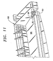
- One end of the lift plate 28 has a portion 29 (see FIG. 11 ) bent at a right angle thereto with an opening 30 to fit over a post 31.
- the post 31 is a portion of a deflector assembly 32, which is formed of molded plastic.
- One side of the deflector assembly 32 is secured to a side frame 33 (see FIG. 1 ) of the printer 11 by screws 34 passing through a pair of openings 34A (see FIG. 8 ) in a flat vertical portion 34B of the deflector assembly 32.
- the deflector assembly 32 has its other side similarly secured to another side frame (not shown) of the printer 11 (see FIG. 1 ) through openings 34C (see FIG. 9 ) in a flat vertical portion 34D.
- the other side of the lift plate 28 (see FIG. 4 ) has an end cap 35, which is formed of molded plastic, affixed thereto.
- the end cap 35 has a bearing portion 36 to receive a post 37 of the deflector assembly 32.
- the post 37 is aligned with the post 31 (see FIG. 11 ).
- the door 13 (see FIG. 1 ) is pivotally supported by the deflector assembly 32.
- the door 13 pivots about an axis aligned with the posts 31 (see FIG. 11 ) and 37 (see FIG. 2 ), which form the pivot axis of the lift plate 28.
- the door 13 (see FIG. 1 ) has a portion 38 pivotally mounted on the post 31 (see FIG. 11 ) and a portion 39 (see FIG. 1 ) pivotally mounted on the post 37.
- the lift plate 28 (see FIG. 2 ) is held in its lowermost position through the cam 23 engaging a cam follower 40, which is a roller, rotatably supported by a pair of upstanding ears 41 on the end cap 35.
- the cam follower 40 is held against the cam 23 by a spring 42 (see FIG. 9 ), which has its upper end bearing against the bottom surface of the end cap 35 and its lower end engaging a flat surface 43 of the deflector assembly 32.
- a pivotally mounted separator arm or carrier 45 (see FIG. 7 ) is pivotally mounted on the deflector assembly 32 (see FIG. 8 ).
- the deflector assembly 32 has a pair of aligned studs 46 and 47 for disposition within arcuate portions 48 (see FIG. 7 ) on opposite sides of the lower end of the separator arm 45.
- the separator arm or carrier 45 has a pair of aligned bearing support areas 49 and 50 in its side walls 51 and 52, respectively.
- the bearing support areas 49 and 50 receive pivot pins 53 (see FIG. 6 ) and 54, respectively, extending from opposite sides of a pad housing 55 to pivotally support the pad housing 55 on the separator arm 45 (see FIG. 7 ).
- the pad housing 55 (see FIG. 6 ) has a separator pad 56 fixed thereto, preferably by a suitable adhesive.
- the separator pad 56 is formed of a material having a greater coefficient of friction with respect to each of the sheets 16 (see FIG. 3 ) of paper than the coefficient of friction between two of the adjacent sheets 16. However, the coefficient of friction of the material of the separator pad 56 (see FIG. 6 ) with each of the sheets 16 (see FIG. 3 ) of paper is less than the coefficient of friction between the rubber portion 25 of the pick roll 24 and each of the sheets 16 of paper.
- One suitable example of the material of the separator pad 56 is a polymer sold by Dow Chemical Company under the trademark PELLETHANE as Series 2355-75. To obtain a desired coefficient of friction of 1.0 against 20 pound xerographic paper, the top surface of the polymer is ground to remove the mold skin.
- the buckling spring 57 has its upper end mounted on a downwardly extending post 57' on the pad housing 55 and its lower end disposed within in inclined track 58 in the separator arm 45.
- the buckling spring 57 exerts a relatively light force of about 20 grams on the bottom of the pad housing 55.
- the spring 42 (see FIG. 9 ) continues to act on the end cap 35 to pivot the lift plate 28 about the posts 31 (see FIG. 8 ) and 37 upwardly from the home position of FIG. 3 to the pick position of FIG. 5 .
- the cam follower 40 does not engage the cam 23 but is slightly spaced therefrom.
- the upward pivotal motion of the lift plate 28 by the spring 42 ceases when the top sheet 16 (see FIG 5 ) of the stack on the lift plate 28 engages the pick roll 24.
- the pick roll 24 has been rotated to the position in which the rubber portion 25 engages and advances the uppermost sheet 16 (see FIG. 3 ) in the stack on the lift plate 28.
- the lift plate 28 In its uppermost position, the lift plate 28 is disposed, as shown in FIG. 5 , so that the rubber portion 25 of the pick roll 24 engages the uppermost sheet of the sheets 16 supported by the lift plate 28.
- the position of the lift plate 28 in FIG. 5 is when only one of the sheets 16 is remaining on the lift plate 28. It should be understood that the final position of the lift plate 28 depends upon the number of the sheets 16 remaining on the lift plate 28.
- a depressed portion 62 of the lift plate 28 engages a plurality of ribs 63 on the separator arm or carrier 45. This pivots the separator arm 45 to prevent a spring 64 from exerting a force on the separator pad 56.
- One end of the spring 64 fits around a projecting portion 65 (see FIG. 8 ) on an inclined surface 66 of the deflector assembly 32.
- the other end of the spring 64 fits within a hollow cylinder 67 on the bottom of a portion 68 (see FIG. 7 ) of the separator arm 45.
- the spring 64 (see FIG. 3 ), which produces a force of about 250 grams on the separator pad 56, is not applied against the pick roll 24 when the pick roll 24 and the lift plate 28 are in the home position.
- the buckling spring 57 is acting against the end portions 26 and 27 (see FIG. 4 ) of the pick roll 24 (see FIG. 3 ) to move the separator pad 56 to the elevated position of FIG. 10 . Because of the higher angle of the separator pad 56 relative to the axis of the pick roll 24, the separator pad 56 is more effective in preventing the advancement of the underlying sheets 16
- the low force produced by the buckling spring 57 is not sufficient to enable advancement and separation of the uppermost sheet of the sheets 16 from the stack when the pick roll 24 is in its pick position of FIG. 5 .
- the spring 64 exerts a force through the portion 68 (see FIG. 7 ) of the separator arm 45. This is because pivoting of the lift plate 28 (see FIG. 5 ) to its upper position has allowed the separator arm 45 to pivot to a position in which a raised end 69 (see FIG.
- the lift plate 28 has a restraint pad 70 disposed on top of the depressed portion 62.
- the restraint pad 70 prevents shifting of the stack of the she ets 16 through restraining the bottom sheet 16 of the stack.
- One suitable example of the material of the restraint pad 70 is a cellular urethane sold under the trademark PORON as Part No. 4701-05 30-062-1637 by Rogers Corporation, Rogers, Connecticut.
- one surface is ground to remove the mold skin to provide the correct coefficient of friction against the sheet 16 (see FIG. 5 ) of paper.
- the sheet 16 of paper After the sheet 16 of paper is advanced past the separator pad 56, it advances between a driver transport roll 71 and a driven transport roll 72.
- the rolls 71 and 72 advance the sheet 16 of paper to a process station at the printer 11 (see FIG. 1 ).
- sheet feed apparatus 10 has been shown and described as being used with the printer 11, it should be understood that the sheet feed apparatus 10 may be used with any apparatus feeding a sheet from a stack to a process station, for example, in which only one sheet is to be fed from the stack to the processing station.
- An advantage of this invention is that the adverse effects of skew and other print degradation in an edge aligned system are significantly reduced.
- Another advantage of this invention is that it decreases picking of multiple sheets from a stack of sheets in an edge aligned system.
Landscapes
- Engineering & Computer Science (AREA)
- Mechanical Engineering (AREA)
- Sheets, Magazines, And Separation Thereof (AREA)
- Handling Of Cut Paper (AREA)
- Paper Feeding For Electrophotography (AREA)
Description
- This invention relates to a sheet feeding apparatus in which feeding of more than an uppermost sheet of media from a stack of sheets is prevented so that only one sheet is fed to a process station and, more particularly, to a friction pad for exerting different forces on a pick roll of the sheet feeding apparatus depending on the position of the fed sheet along its feed path.
-
US-A-5 058 877 describes a sheet feeding apparatus having support means for supporting a plurality of sheets in a stack, an intermittently driven pick roll, a friction pad and a spring for causing said friction pad to exert a force on said pick roll. - Friction separator paper pick mechanisms are commonly used in printers and copiers, for example, to feed a single sheet of paper into transportrolls, which forward the single sheet to a process station of the printer or copier. A typical friction separator paper pick mechanism includes a spring loaded paper-lift plate, a high friction pick roll, and a spring loaded separator pad.
- The separator pad is formed of a material having a coefficient of friction with paper greater than the coefficient of friction between adjacent sheets of paper but smaller than the coefficient of friction between the pick roll and a sheet of paper. This relationship of the coefficients of friction insures that the pad will not prevent advancement of the sheet by the pick roll but will separate any sheet beneath the uppermost sheet. The geometry of the mechanism has both the paper-lift plate and the separator pad contact the high friction pick roll with the uppermost sheet in the paper-lift plate contacting the high friction pick roll prior to the sheet being fed between the separator pad and the high friction pick roll.
- When actuated to advance a sheet of paper from a stack, the paper-lift plate moves to a position in which the uppermost sheet in the stack is engaged by the intermittently driven pick roll so that the uppermost sheet is fed into a nip formed between the pick roll and the separator pad. If only a single sheet is picked by the pick roll, the fed sheet will pass through the nip formed between the pick roll and the separator pad into the printer or copier because of the high coefficient of friction between the pick roll and the sheet in comparison with the coefficient of friction between the separator pad and the sheet. If two or more sheets are picked by the pick roll as occurs with many high friction media, the purpose of the separator pad is to restrain all but the uppermost sheet in the stack from being advanced during a specific cycle of operation.
- After the sheet is fed to the transport rolls for advancement into the printer or copier, it is critical to minimize drag on the fed sheet in an edge aligned printer or copier. This is because one of the sheet's side edges rides along guide means as the sheet is transported by relatively small rollers and relatively low nip forces.
- In an edge aligned system, extraneous drag on the sheet can cause skew of print and other imaging degradation. In severe cases, the extraneous drag on the sheet can cause the sheet to slip in the transport rolls whereby the sheet jams in its feed path through the printer or copier.
- Since the drag must be minimized in an edge aligned system, the spring load between the sheet and the pick roll is normally removed after the sheet is picked from the stack by the pick roll to open the nip. This is accomplished by either moving the paper-lift plate away from the pick roll or raising the pick roll away from the stack of sheets. The spring load between the separator pad and the pick roll also is removed to prevent the unwanted drag.
- This opening of the two nips is the principal contributor to feeding more than one sheet during a cycle of operation in this type of mechanism. This is because opening of the two nips enables one or more of the underlying sheets in the stack to be dragged into the printer along with the uppermost sheet unless the motion of the underlying sheets is retarded in some manner.
- Retarding of the motion of the underlying sheets is usually accomplished by rotating an arm having sharp steps, which catch the underlying sheets, into the sheet feed path by the same mechanism, which drops the separator pad from engagement with the pick roll. In this arrangement, the timing, geometry, and tolerances are very critical since the retarding means must be disposed to catch the underlying sheets as the nip is opened or multiple sheets will be fed. Even when the retarding means is disposed in its proper position, media of high friction and low weight in particular still tend to be dragged into the printer or copier by the fed sheet through "jumping" over the retarding means.
- This problem is averted in a center driven system by having the spring loaded paper-lift plate and the spring loaded separator pad remain in contact with the high friction pick roll throughout the feeding of the entire stack. This is possible because it is not necessary to open the nips after feeding of each sheet since center driven sheet feeders for printers and copiers have much larger transport rolls, much higher nip forces, and no reference edge with which the sheet must be aligned. Of course, this is a more costly system in comparison with the edge aligned system having the relatively smaller rollers.
- The much larger transport rolls of the center driven system can exert a sufficient force to pull each sheet from the nips without having to open either of the two nips. The pick roll is usually driven through a one-way clutch to aid the transport rolls in moving the sheet.
- Since the two nips are not opened and closed for each fed sheet in the center driven system, the timing, geometry, and tolerances are not as critical in terms of feed reliability as in the edge aligned system. This is because the sheets are always tightly held in the nips so that there is less chance of the underlying sheets being dragged into the printer or copier along with the uppermost sheet. However, as previously mentioned, the center driven system requires a higher cost for its parts in comparison with the edge aligned system, and it also requires more power to operate.
-
JP-U-647243 - Cams as such are known e.g. from
US-A-5 186 488 . - The sheet feeding apparatus of the present invention overcomes the foregoing problems of the edge aligned system through always maintaining a nip between the pick roll and the friction or separator pad. In the present invention, the friction or separator pad always exerts a force on the pick roll to maintain the nip. A first force is exerted on the friction or separator pad, preferably through first resilient means, when a sheet is being advanced by the pick roll. A second force, smaller than the first force, is exerted on the friction or separator pad, preferably through second resilient means, when the pick roll is no longer being driven.
- The friction or separator pad is preferably pivotally supported by a pivotally mounted separator arm or carrier. When a sheet is being fed by the pick roll, the pad is at a first angle to the pick roll and subjected to the first force. When the pick roll is stopped, the pad is at a second angle, greater than the first angle, to the pick roll to provide a greater obstacle to any underlying sheet trying to pass over it and subjected to the second force.
- An object of this invention is to provide a separator pad exerting two different forces on a pick roll in accordance with the position of the fed sheet.
- Another object of this invention is to improve the feed reliability of an edge aligned system.
- A further object of this invention is to maintain a nip between a friction pad and a pick roll after a pick-up lift plate ceases to be in a position in which it holds the uppermost sheet in a stack against the pick roll.
- Other objects of this invention will be readily perceived from the following description, claims, and drawings.
- The attached drawings illustrate a preferred embodiment of the invention, in which:
-
FIG. 1 is a perspective view of a portion of a sheet feed apparatus of a printer with the sheet feed apparatus having a friction or separator pad of the present invention. -
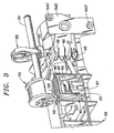
FIG. 2 is a perspective view, partly in section, of a portion of the sheet feed apparatus ofFIG. 1 and taken from the side ofFIG. 1 with a pick roll of the sheet feed apparatus in its home position. -
FIG. 3 is a side elevational view, partly in section, of a portion of the sheet feed apparatus ofFIG. 1 with the pick roll of the sheet feed apparatus in its home position and showing a plurality of sheets in a stack on a lift plate. -
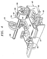
FIG. 4 is a perspective view, partly in section, of a portion of the sheet feed apparatus ofFIG. 1 and showing the pick roll of the sheet feed apparatus in its pick position. -
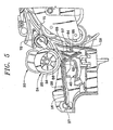
FIG. 5 is a side elevational view, partly in section, of a portion of the sheet feed apparatus ofFIG. 1 with the pick roll of the sheet feed apparatus in its pick position and showing only a single sheet in the lift plate. -
FIG. 6 is an enlarged perspective view of a separator pad assembly. -
FIG. 7 is an enlarged perspective view of a separator arm or carrier for pivotally supporting the separator pad assembly ofFIG. 6 . -
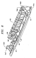
FIG. 8 is a perspective view of a deflector assembly pivotally supporting the separator arm and the separator pad. -
FIG. 9 is a rear elevational view, partly in section, of a portion of the sheet feed apparatus ofFIG. 1 with the pick roll of the sheet feed apparatus in its pick position and showing the two springs that provide the two forces or the friction or separator pad. -
FIG. 10 is a rear elevational view of the separator pad assembly ofFIG. 6 assembled on the separator arm or carrier ofFIG. 7 with the pick roll of the sheet feed apparatus in its home position and showing the two springs that provide the two forces on the friction or separator pad with the friction or separator pad at ts maximum angle. -
FIG. 11 is an enlarged perspective view of a portion of the sheet feed apparatus ofFIG. 1 showing the pivotal mounting of one side of the lift plate on the deflector assembly. - Referring to the drawings and particularly
FIG. 1 , there is shown asheet feed apparatus 10 of a printer 11. Thesheet feed apparatus 10 includes atray assembly 12, which is mounted on a pivotally mounteddoor 13 of the printer 11. - The
tray assembly 12 hasreference edges FIG. 3 ) of a media such as paper, for example, abuts during its advancement. A movable paper guide 17 (seeFIG. 1 ) engages the right edge of each of the sheets 16 (seeFIG. 3 ) when they are disposed in a stack in the tray assembly 12 (seeFIG. 1 ). Thus, thesheet feed apparatus 10 uses an edge aligned system for guiding the sheets 16 (seeFIG. 3 ) of the stack to the printer 11 (seeFIG. 1 ). - The
tray assembly 12 includes afirst slide 18 slidable within an opening 18' and asecond slide 19 slidable within an opening 19A in thefirst slide 18. Ametal wire 19B is attached to thesecond slide 19 to pull it from thefirst slide 18 until a stop (not shown) in thesecond slide 19 engages a stop (not shown) on thefirst slide 18. The same arrangement exists between thefirst slide 18 and the interior of thetray assembly 12. - Advancement of the uppermost sheet 16 (see
FIG. 3 ) of the stack is accomplished whenever a solenoid 20 (seeFIG. 1 ) is energized by a signal from a printer or copier (not shown), for example, that one of the sheets 16 (seeFIG. 3 ) is to be advanced to the printer 11 (seeFIG. 1 ) for printing. Thesolenoid 20 activates a pickclutch assembly 21 to cause a shaft 22 (seeFIG. 2 ) to be rotated through a cycle of operation by a motor (not shown). Theshaft 22 has acam 23 and apick roll 24 affixed thereto for rotation therewith. - The
pick roll 24 includes acentral portion 25 of rubber having a constant radius.End portions 26 and 27 (seeFIG. 1 ) of thepick roll 24 are formed of acetal, which has a very low coefficient of friction with paper. The periphery of each of theend portions central portion 25. - When the
shaft 22 is rotated, therubber portion 25 of thepick roll 24 is rotated into the engagement with the uppermost sheet of the sheets 16 (seeFIG. 3 ) in the stack resting on a metal lift plate 28 (seeFIG. 1 ). When therubber portion 25 of thepick roll 24 engages the uppermost sheet 16 (seeFIG. 3 ), the sh set 16 is advanced from the stack, which is supported by the lift plate 28 (seeFIG. 1 ). - The
lift plate 28 is pivotally mounted for movement between the position ofFIG. 2 , which is the home position of thepick roll 24, and the position ofFIG. 4 , which is the pick position of thepick roll 24 in which the upper nost sheet 16 (seeFIG. 5 ) is engaged by thepick roll 24 for advancement from the stack of thesheets 16. One end of thelift plate 28 has a portion 29 (seeFIG. 11 ) bent at a right angle thereto with anopening 30 to fit over apost 31. Thepost 31 is a portion of adeflector assembly 32, which is formed of molded plastic. - One side of the
deflector assembly 32 is secured to a side frame 33 (seeFIG. 1 ) of the printer 11 byscrews 34 passing through a pair ofopenings 34A (seeFIG. 8 ) in a flatvertical portion 34B of thedeflector assembly 32. Thedeflector assembly 32 has its other side similarly secured to another side frame (not shown) of the printer 11 (seeFIG. 1 ) through openings 34C (seeFIG. 9 ) in a flatvertical portion 34D. - The other side of the lift plate 28 (see
FIG. 4 ) has anend cap 35, which is formed of molded plastic, affixed thereto. Theend cap 35 has a bearingportion 36 to receive apost 37 of thedeflector assembly 32. Thepost 37 is aligned with the post 31 (seeFIG. 11 ). - The door 13 (see
FIG. 1 ) is pivotally supported by thedeflector assembly 32. Thedoor 13 pivots about an axis aligned with the posts 31 (seeFIG. 11 ) and 37 (seeFIG. 2 ), which form the pivot axis of thelift plate 28. Thus, the door 13 (seeFIG. 1 ) has aportion 38 pivotally mounted on the post 31 (seeFIG. 11 ) and a portion 39 (seeFIG. 1 ) pivotally mounted on thepost 37. - In the home position, the lift plate 28 (see
FIG. 2 ) is held in its lowermost position through thecam 23 engaging acam follower 40, which is a roller, rotatably supported by a pair of upstanding ears 41 on theend cap 35. Thecam follower 40 is held against thecam 23 by a spring 42 (seeFIG. 9 ), which has its upper end bearing against the bottom surface of theend cap 35 and its lower end engaging aflat surface 43 of thedeflector assembly 32. - A pivotally mounted separator arm or carrier 45 (see
FIG. 7 ) is pivotally mounted on the deflector assembly 32 (seeFIG. 8 ). Thedeflector assembly 32 has a pair of alignedstuds FIG. 7 ) on opposite sides of the lower end of theseparator arm 45. - The separator arm or
carrier 45 has a pair of aligned bearingsupport areas side walls support areas FIG. 6 ) and 54, respectively, extending from opposite sides of apad housing 55 to pivotally support thepad housing 55 on the separator arm 45 (seeFIG. 7 ). - The pad housing 55 (see
FIG. 6 ) has aseparator pad 56 fixed thereto, preferably by a suitable adhesive. Theseparator pad 56 is formed of a material having a greater coefficient of friction with respect to each of the sheets 16 (seeFIG. 3 ) of paper than the coefficient of friction between two of theadjacent sheets 16. However, the coefficient of friction of the material of the separator pad 56 (seeFIG. 6 ) with each of the sheets 16 (seeFIG. 3 ) of paper is less than the coefficient of friction between therubber portion 25 of thepick roll 24 and each of thesheets 16 of paper. - One suitable example of the material of the separator pad 56 (see
FIG. 6 ) is a polymer sold by Dow Chemical Company under the trademark PELLETHANE as Series 2355-75. To obtain a desired coefficient of friction of 1.0 against 20 pound xerographic paper, the top surface of the polymer is ground to remove the mold skin. - When the sheet feed apparatus 10 (see
FIG. 3 ) is in its home position, the friction orseparator pad 56 is engaged by theend portions pick roll 24 extending beyond therubber portion 25. The force of a bucklingspring 57 holds theseparator pad 56 against thepick roll 24. - The buckling
spring 57 has its upper end mounted on a downwardly extendingpost 57' on thepad housing 55 and its lower end disposed within ininclined track 58 in theseparator arm 45. The bucklingspring 57 exerts a relatively light force of about 20 grams on the bottom of thepad housing 55. - As the cam 23 (see
FIG. 5 ) rotates during a cycle of operation, the spring 42 (seeFIG. 9 ) continues to act on theend cap 35 to pivot thelift plate 28 about the posts 31 (seeFIG. 8 ) and 37 upwardly from the home position ofFIG. 3 to the pick position ofFIG. 5 . In the pick position ofFIG. 4 , thecam follower 40 does not engage thecam 23 but is slightly spaced therefrom. The upward pivotal motion of thelift plate 28 by the spring 42 (seeFIG. 9 ) ceases when the top sheet 16 (seeFIG 5 ) of the stack on thelift plate 28 engages thepick roll 24. - When the
cam 23 has been rotated to the pick position ofFIG. 4 , thepick roll 24 has been rotated to the position in which therubber portion 25 engages and advances the uppermost sheet 16 (seeFIG. 3 ) in the stack on thelift plate 28. In its uppermost position, thelift plate 28 is disposed, as shown inFIG. 5 , so that therubber portion 25 of thepick roll 24 engages the uppermost sheet of thesheets 16 supported by thelift plate 28. The position of thelift plate 28 inFIG. 5 is when only one of thesheets 16 is remaining on thelift plate 28. It should be understood that the final position of thelift plate 28 depends upon the number of thesheets 16 remaining on thelift plate 28. - In the home position of
FIG. 3 in which thelift plate 28 is at its lowermost position and has a plurality of thesheets 16 thereon, adepressed portion 62 of thelift plate 28 engages a plurality ofribs 63 on the separator arm orcarrier 45. This pivots theseparator arm 45 to prevent aspring 64 from exerting a force on theseparator pad 56. - One end of the
spring 64 fits around a projecting portion 65 (seeFIG. 8 ) on aninclined surface 66 of thedeflector assembly 32. The other end of the spring 64 (seeFIG. 9 ) fits within ahollow cylinder 67 on the bottom of a portion 68 (seeFIG. 7 ) of theseparator arm 45. - Thus, the spring 64 (see
FIG. 3 ), which produces a force of about 250 grams on theseparator pad 56, is not applied against thepick roll 24 when thepick roll 24 and thelift plate 28 are in the home position. As a result, only the small force of the bucklingspring 57 is acting against theend portions 26 and 27 (seeFIG. 4 ) of the pick roll 24 (seeFIG. 3 ) to move theseparator pad 56 to the elevated position ofFIG. 10 . Because of the higher angle of theseparator pad 56 relative to the axis of thepick roll 24, theseparator pad 56 is more effective in preventing the advancement of theunderlying sheets 16 - This arrangement insures that the nip between the pick roll 24 (see
FIG. 3 ) and theseparator pad 56 is always blocked. Of course, there is a very low coefficient of friction acting on the movingsheet 16 of paper because theseparator pad 56 is forcing thesheet 16 to bear against theend portions 26 and 27 (seeFIG. 4 ) of the pick roll 24 (seeFIG. 3 ) rather than therubber portion 25. - While the coefficient of friction of the
separator pad 56 with thesheets 16 is greater than the coefficient of friction between two of thesheets 16 so that this will prevent more than one of thesheets 16 from passing through the nip, the low force produced by the bucklingspring 57 is not sufficient to enable advancement and separation of the uppermost sheet of thesheets 16 from the stack when thepick roll 24 is in its pick position ofFIG. 5 . When thepick roll 24 is in its pick position, thespring 64 exerts a force through the portion 68 (seeFIG. 7 ) of theseparator arm 45. This is because pivoting of the lift plate 28 (seeFIG. 5 ) to its upper position has allowed theseparator arm 45 to pivot to a position in which a raised end 69 (seeFIG. 7 ) of theportion 68 of theseparator arm 45 is engaging the pad housing 55 (seeFIG. 5 ) so that the force of thespring 64 is exerted through the friction orseparator pad 56 to insure that the uppermost of thesheets 16 is held against therubber portion 25 of thepick roll 24 with a sufficient force to enable advancement and separation of theuppermost sheet 16. - Accordingly, sufficient force is applied by the spring 64 ( see
FIG. 5 ) to insure advancement and separation of theuppermost sheet 16 from the stack by thepick roll 24. At the same time, when thepick roll 24 is in the home position ofFIG. 3 , only the force of the bucklingspring 57 is effective. However, this relatively small force of about 20 grams is sufficient to prevent opening of the nip between thepick roll 24 and theseparator pad 56 at any time. - The
lift plate 28 has arestraint pad 70 disposed on top of thedepressed portion 62. Therestraint pad 70 prevents shifting of the stack of theshe ets 16 through restraining thebottom sheet 16 of the stack. - One suitable example of the material of the
restraint pad 70 is a cellular urethane sold under the trademark PORON as Part No. 4701-05 30-062-1637 by Rogers Corporation, Rogers, Connecticut. To obtain the desired coefficient of friction against paper, one surface is ground to remove the mold skin to provide the correct coefficient of friction against the sheet 16 (seeFIG. 5 ) of paper. - After the
sheet 16 of paper is advanced past theseparator pad 56, it advances between adriver transport roll 71 and a driventransport roll 72. Therolls sheet 16 of paper to a process station at the printer 11 (seeFIG. 1 ). - While the
sheet feed apparatus 10 has been shown and described as being used with the printer 11, it should be understood that thesheet feed apparatus 10 may be used with any apparatus feeding a sheet from a stack to a process station, for example, in which only one sheet is to be fed from the stack to the processing station. - An advantage of this invention is that the adverse effects of skew and other print degradation in an edge aligned system are significantly reduced. Another advantage of this invention is that it decreases picking of multiple sheets from a stack of sheets in an edge aligned system.
- For purposes of exemplification, a particular embodiment of the invention has been shown and described according to the best present understanding thereof. However, it will be apparent that changes and modifications in the arrangement and construction of the parts thereof may be resorted to without departing from the scope of the invention.
Claims (18)
- A sheet feeding apparatus (10) for feeding a single sheet from a stack of sheets (16) including:support means (28) for supporting a plurality of sheets in a stack and pivotable between a home position and a pick position;an intermittently driven pick roll (24) affixed to a shaft (22) for rotation therewith for engaging the uppermost of the sheets in the stack to advance the uppermost sheet from the stack;a friction pad (56) disposed downstream from engagement of said pick roll with the uppermost sheet of the stack of sheets supported by said support means, said friction pad always exerting a force on said pick roll;first causing means (64) for causing said friction pad to exert a first force on said pick roll when said pick roll is driven and engages the uppermost sheet of the stack of sheets on said support means to remove the sheet therefrom while the uppermost sheet is still supported by said support means in said pick position;and second causing means (57) for causing said friction pad to exert a second force smaller than the first force on said pick roll when relative movement occurs between said pick roll and said support means from said pick position to said home position, so that the uppermost sheet of the stack of sheets is held between said pick roll and said friction pad;
characterized bya cam (23) affixed to the shaft (22) for rotation therewith movable with said pick roll (24) when said pick roll (24) is driven to cause said relative movement between said pick roll (24) and said support means (28) which removes said first force. - The apparatus according to claim 1 including pivotal mounting means (45) for pivotally mounting said friction pad to change the angle of said friction pad relative to the axis of rotation of said pick roll in accordance with whether said support means is disposed in a first position so that the uppermost sheet of the stack of sheets supported by said support means is engaged by said pick roll or in a second position in which the uppermost sheet of the stack of sheets is held between said pick roll and said friction pad.
- The apparatus according to claim 2 in which said pivotal mounting means (45) includes:a pivotally mounted carrier;said pivotally mounted carrier having said friction pad pivotally supported thereon;said first causing means acting on said pivotally mounted carrier to cause pivoting of said pivotally mounted carrier so that said friction pad exerts the first force on said pick roll;and said second causing means causing said friction pad to pivot relative to said pivotally mounted carrier so that said friction pad exerts the second force on said pick roll when said first causing means is not effective.
- The apparatus according to claim 3 in which said support means (28) engages said pivotally mounted carrier to render said pivotally mounted carrier ineffective when said support means is not in its first position in which the uppermest sheet may be removed from said support means by said pick roll.
- The apparatus according to claim 3 in which said support means (28) includes a pivotally mounted lift plate engaging said pivotally mounted carrier.
- The apparatus according to claim 5 in which said first causing means (64) includes first resilient means acting on said pivotally mounted carrier.
- The apparatus according to claim 4 in which said first causing means (64) includes first resilient means acting on said pivotally mounted carrier.
- The apparatus according to claim 3 including:a pad housing (55) having said friction pad fixed thereto;pivotal mounting means for pivotally mounting said pad housing on said pivotally mounted carrier to pivotally support said pad housing on said pivotally mounted carrier for pivotal movement relative to said pivotally mounted carrier.
- The apparatus according to claim 8 in which said second causing means (57) includes resilient means acting between said pad housing and said pivotally nounted carrier to exert the second force on said pad housing for transmission to said pick roll.
- The apparatus according to claim 9 in which said second causing means (57) includes resilient means acting on said friction pad.
- The apparatus according to claim 3 in which said first causing means (64) includes first resilient means acting on said pivotally mounted carrier.
- The apparatus according to claim 11 in which said second causing means (57) includes second resilient means acting on said friction pad.
- The apparatus according to claim 3 in which said second causing means (57) is effective when said support means moves to its second position so that said friction pad pivots relative to said pivotally mounted carrier to exert the second force on said pick roll.
- The apparatus according to claim 13 in which said second causing means (57) includes resilient means acting on said friction pad.
- The apparatus according to claim 3 in which said first causing means (64) includes first resilient means acting on said friction pad.
- The apparatus according to claim 15 in which said second causing means (57) includes second resilient means acting on said friction pad.
- The apparatus according to claim 3 in which said second causing means (57) includes resilient means acting on said friction pad.
- The apparatus according to claim 1 including guide means for engaging a side edge of each sheet to guide each sheet during its advancement by said pick roll (24).
Applications Claiming Priority (2)
| Application Number | Priority Date | Filing Date | Title |
|---|---|---|---|
| US850897 | 1997-05-02 | ||
| US08/850,897 US5996989A (en) | 1997-05-02 | 1997-05-02 | Sheet separator friction pad |
Publications (3)
| Publication Number | Publication Date |
|---|---|
| EP0875474A1 EP0875474A1 (en) | 1998-11-04 |
| EP0875474B1 EP0875474B1 (en) | 2001-11-28 |
| EP0875474B2 true EP0875474B2 (en) | 2009-01-28 |
Family
ID=25309400
Family Applications (1)
| Application Number | Title | Priority Date | Filing Date |
|---|---|---|---|
| EP98107939A Expired - Lifetime EP0875474B2 (en) | 1997-05-02 | 1998-04-30 | Sheet separator friction pad |
Country Status (7)
| Country | Link |
|---|---|
| US (1) | US5996989A (en) |
| EP (1) | EP0875474B2 (en) |
| JP (1) | JP3882066B2 (en) |
| KR (1) | KR100701371B1 (en) |
| CN (2) | CN1112613C (en) |
| DE (1) | DE69802612T2 (en) |
| TW (1) | TW418158B (en) |
Families Citing this family (21)
| Publication number | Priority date | Publication date | Assignee | Title |
|---|---|---|---|---|
| JP3581519B2 (en) * | 1997-04-24 | 2004-10-27 | キヤノン株式会社 | Sheet storage cassette, sheet feeding apparatus and image forming apparatus provided with the same |
| JP3702600B2 (en) * | 1997-08-25 | 2005-10-05 | ブラザー工業株式会社 | Sheet transport device |
| JP3743138B2 (en) * | 1997-10-15 | 2006-02-08 | ブラザー工業株式会社 | Sheet transport device |
| US6446960B1 (en) * | 1999-03-04 | 2002-09-10 | Fuji Photo Film Co., Ltd. | Sheet feeding device |
| KR100370206B1 (en) * | 1999-12-30 | 2003-01-29 | 삼성전자 주식회사 | Paper pick-up apparatus having frictional pad for printer |
| JP3733841B2 (en) * | 2000-07-06 | 2006-01-11 | セイコーエプソン株式会社 | Sheet feeding device |
| US6824131B2 (en) * | 2000-08-08 | 2004-11-30 | Ricoh Company, Ltd. | Method and apparatus for image forming and effectively performing sheet feeding using a sheet feed roller and a tilt member |
| JP3685144B2 (en) * | 2002-03-29 | 2005-08-17 | ブラザー工業株式会社 | Paper feeding device and image forming apparatus having the same |
| US6824133B2 (en) | 2002-10-17 | 2004-11-30 | Hewlett-Packard Development Company, L.P. | Stack monitoring method and system |
| US6978997B2 (en) * | 2003-11-24 | 2005-12-27 | Lexmark International, Inc. | Recovery from double media feed |
| US7152859B2 (en) * | 2004-06-15 | 2006-12-26 | Xerox Corporation | Sheet separator |
| KR100739780B1 (en) * | 2005-12-26 | 2007-07-13 | 삼성전자주식회사 | Image forming apparatus with shutter arm unit |
| CN101348195B (en) * | 2007-07-19 | 2010-06-09 | 光宝科技股份有限公司 | Automatic paper feeder |
| US7913992B2 (en) * | 2007-12-19 | 2011-03-29 | Lexmark International, Inc. | Methods of moving a media sheet in a scanning device |
| KR101521076B1 (en) * | 2008-12-19 | 2015-05-18 | 삼성전자 주식회사 | Image forming apparatus and paper feeding device thereof |
| FR2955093A1 (en) * | 2009-12-10 | 2011-07-15 | Sagem Comm | Processing device e.g. photocopier, for processing documents e.g. identity card, has decollator introducing documents into internal path in disengaging position such that introduced documents is thicker than documents introduced in bundle |
| JP5760673B2 (en) * | 2011-05-16 | 2015-08-12 | セイコーエプソン株式会社 | Medium feeding device, scanner device, recording device |
| EP2551223B1 (en) * | 2011-07-29 | 2015-03-11 | Canon Kabushiki Kaisha | Sheet stacking apparatus and image forming apparatus |
| CN102942017A (en) * | 2012-11-26 | 2013-02-27 | 昆山特力伯传动科技有限公司 | Conveying driving component of conveying belt component |
| CN104925568B (en) * | 2014-03-17 | 2017-03-15 | 柯尼卡美能达办公系统研发(无锡)有限公司 | Discharge tray unit, after-treatment device, image processing system and system |
| CN105668274B (en) * | 2014-10-14 | 2020-05-26 | 虹光精密工业股份有限公司 | Paper separating device |
Citations (6)
| Publication number | Priority date | Publication date | Assignee | Title |
|---|---|---|---|---|
| US4717139A (en) † | 1985-03-29 | 1988-01-05 | Canon Kabushiki Kaisha | Sheet feeding apparatus |
| US5186446A (en) † | 1990-10-03 | 1993-02-16 | Ricoh Company, Ltd. | Recycling automatic document feeder |
| US5240242A (en) † | 1990-07-05 | 1993-08-31 | Canon Kabushiki Kaisha | Sheet feeding device |
| US5318287A (en) † | 1991-09-11 | 1994-06-07 | Konica Corporation | Bypass sheet feeding device |
| JPH0647243U (en) † | 1992-12-02 | 1994-06-28 | 沖電気工業株式会社 | Automatic document feeder |
| US5454559A (en) † | 1991-01-07 | 1995-10-03 | Sumio Gomu Kogyo Kabushiki Kaisha | Rubber member for paper feed device |
Family Cites Families (20)
| Publication number | Priority date | Publication date | Assignee | Title |
|---|---|---|---|---|
| US4113244A (en) * | 1975-04-15 | 1978-09-12 | Kurt Ruenzi | Apparatus for automatically feeding individual sheets from a stack through an office machine |
| JPS5941892B2 (en) * | 1978-09-05 | 1984-10-11 | ロ−レルバンクマシン株式会社 | Feeding device for paper sheet counting machine |
| US4368880A (en) * | 1980-08-13 | 1983-01-18 | Masaaki Shimizu | Machine for feeding sheets of paper |
| JPS5992839A (en) * | 1982-11-16 | 1984-05-29 | Minolta Camera Co Ltd | Paper feeder |
| JPS59172339A (en) * | 1983-03-18 | 1984-09-29 | Deyupuro Seizo Kk | Paper feeder |
| DE3674066D1 (en) * | 1985-05-24 | 1990-10-18 | Mita Industrial Co Ltd | PAPER FEEDER. |
| JPS62140041U (en) * | 1986-02-28 | 1987-09-03 | ||
| NL8601261A (en) * | 1986-05-20 | 1987-12-16 | Oce Nederland Bv | DEVICE FOR DRAINING SHEETS FROM THE TOP OF A STACK. |
| JPH0829850B2 (en) * | 1987-03-02 | 1996-03-27 | 三田工業株式会社 | Friction pad fixture |
| US5058877A (en) * | 1989-05-19 | 1991-10-22 | Ricoh Company, Ltd. | Automatic cut-sheet feeding apparatus |
| JPH03192039A (en) * | 1989-12-18 | 1991-08-21 | Matsushita Graphic Commun Syst Inc | Image reading-out device |
| US5056604A (en) * | 1990-05-02 | 1991-10-15 | Xerox Corporation | Sheet feeder devices |
| JP2966054B2 (en) * | 1990-07-13 | 1999-10-25 | キヤノン株式会社 | Sheet feeding device |
| JP2943415B2 (en) * | 1991-03-19 | 1999-08-30 | キヤノン株式会社 | Paper feeder and image forming apparatus using the same |
| US5163668A (en) * | 1991-08-29 | 1992-11-17 | Xerox Corporation | Retard pad assembly with movable compliant entrance guide |
| US5255903A (en) * | 1991-11-12 | 1993-10-26 | Eastman Kodak Company | Sheet feed and alignment apparatus |
| JP2512258B2 (en) * | 1992-03-11 | 1996-07-03 | 松下電器産業株式会社 | Sheet feeding device |
| JPH07267389A (en) * | 1994-03-30 | 1995-10-17 | Tec Corp | Paper feeder |
| US5494277A (en) * | 1994-09-21 | 1996-02-27 | Lexmark International, Inc. | Universal paper feed |
| US5718424A (en) * | 1995-02-01 | 1998-02-17 | Canon Kabushiki Kaisha | Sheet feeding device having a separating and prestressing device |
-
1997
- 1997-05-02 US US08/850,897 patent/US5996989A/en not_active Expired - Lifetime
-
1998
- 1998-04-30 DE DE69802612T patent/DE69802612T2/en not_active Expired - Fee Related
- 1998-04-30 CN CN98109448A patent/CN1112613C/en not_active Expired - Fee Related
- 1998-04-30 EP EP98107939A patent/EP0875474B2/en not_active Expired - Lifetime
- 1998-04-30 CN CNB031087035A patent/CN1277731C/en not_active Expired - Fee Related
- 1998-05-02 KR KR1019980015880A patent/KR100701371B1/en not_active Expired - Fee Related
- 1998-05-06 JP JP13917398A patent/JP3882066B2/en not_active Expired - Fee Related
- 1998-07-18 TW TW087106807A patent/TW418158B/en not_active IP Right Cessation
Patent Citations (6)
| Publication number | Priority date | Publication date | Assignee | Title |
|---|---|---|---|---|
| US4717139A (en) † | 1985-03-29 | 1988-01-05 | Canon Kabushiki Kaisha | Sheet feeding apparatus |
| US5240242A (en) † | 1990-07-05 | 1993-08-31 | Canon Kabushiki Kaisha | Sheet feeding device |
| US5186446A (en) † | 1990-10-03 | 1993-02-16 | Ricoh Company, Ltd. | Recycling automatic document feeder |
| US5454559A (en) † | 1991-01-07 | 1995-10-03 | Sumio Gomu Kogyo Kabushiki Kaisha | Rubber member for paper feed device |
| US5318287A (en) † | 1991-09-11 | 1994-06-07 | Konica Corporation | Bypass sheet feeding device |
| JPH0647243U (en) † | 1992-12-02 | 1994-06-28 | 沖電気工業株式会社 | Automatic document feeder |
Also Published As
| Publication number | Publication date |
|---|---|
| KR19980086728A (en) | 1998-12-05 |
| JP3882066B2 (en) | 2007-02-14 |
| CN1515425A (en) | 2004-07-28 |
| CN1277731C (en) | 2006-10-04 |
| JPH10338373A (en) | 1998-12-22 |
| US5996989A (en) | 1999-12-07 |
| KR100701371B1 (en) | 2007-07-06 |
| TW418158B (en) | 2001-01-11 |
| DE69802612D1 (en) | 2002-01-10 |
| CN1112613C (en) | 2003-06-25 |
| EP0875474A1 (en) | 1998-11-04 |
| DE69802612T2 (en) | 2002-08-01 |
| CN1198546A (en) | 1998-11-11 |
| EP0875474B1 (en) | 2001-11-28 |
Similar Documents
| Publication | Publication Date | Title |
|---|---|---|
| EP0875474B2 (en) | Sheet separator friction pad | |
| US5022642A (en) | Sheet feeding device for a image developing and processing machine | |
| US5931455A (en) | Sheet feeding apparatus and two side image forming apparatus therewith | |
| US5192068A (en) | Sheet feeding and separating apparatus with an improved entrance guide | |
| CA1047970A (en) | Separator card retriever | |
| JPH07199556A (en) | Automatic document feeder | |
| US5230503A (en) | Sheet feeding apparatus with adjustable urging members | |
| JPS6132219B2 (en) | ||
| US5465948A (en) | Sheet feeding and separating apparatus | |
| US5441250A (en) | Sheet feeding apparatus | |
| JP2522391B2 (en) | Sheet material feeder | |
| JP3422237B2 (en) | Paper feeder | |
| MXPA98003435A (en) | Friction pad for ho separator | |
| JPS5822259A (en) | Sorter | |
| US6135436A (en) | Envelope pressing device in printer | |
| JPH08198459A (en) | Sheet feeding apparatus and image forming apparatus provided with the sheet feeding apparatus | |
| JPH0430197Y2 (en) | ||
| JP3128595B2 (en) | Paper feed cassette device and recording device using the same | |
| KR200186325Y1 (en) | Paper pick-up unit for paper cassette | |
| KR200238178Y1 (en) | Device for reduction noise in a printer | |
| EP0367202A2 (en) | Sheet feeding apparatus | |
| HK1065982A (en) | Sheet separator friction pad | |
| JPH07157203A (en) | Paper sheets separating/delivering/accumulating mechanism | |
| JPH0398927A (en) | Paper feeding device | |
| JPH09132336A (en) | Paper feeding and conveying device in image forming apparatus |
Legal Events
| Date | Code | Title | Description |
|---|---|---|---|
| PUAI | Public reference made under article 153(3) epc to a published international application that has entered the european phase |
Free format text: ORIGINAL CODE: 0009012 |
|
| AK | Designated contracting states |
Kind code of ref document: A1 Designated state(s): DE FR GB |
|
| AX | Request for extension of the european patent |
Free format text: AL;LT;LV;MK;RO;SI |
|
| 17P | Request for examination filed |
Effective date: 19990428 |
|
| AKX | Designation fees paid |
Free format text: DE FR GB |
|
| GRAG | Despatch of communication of intention to grant |
Free format text: ORIGINAL CODE: EPIDOS AGRA |
|
| 17Q | First examination report despatched |
Effective date: 20010220 |
|
| GRAG | Despatch of communication of intention to grant |
Free format text: ORIGINAL CODE: EPIDOS AGRA |
|
| GRAG | Despatch of communication of intention to grant |
Free format text: ORIGINAL CODE: EPIDOS AGRA |
|
| GRAH | Despatch of communication of intention to grant a patent |
Free format text: ORIGINAL CODE: EPIDOS IGRA |
|
| GRAH | Despatch of communication of intention to grant a patent |
Free format text: ORIGINAL CODE: EPIDOS IGRA |
|
| GRAA | (expected) grant |
Free format text: ORIGINAL CODE: 0009210 |
|
| AK | Designated contracting states |
Kind code of ref document: B1 Designated state(s): DE FR GB |
|
| RIN1 | Information on inventor provided before grant (corrected) |
Inventor name: WILLIAMS, SCOTT STEPHEN Inventor name: RUSH, EDWARD ALAN Inventor name: CAHILL, DANIEL PAUL |
|
| REG | Reference to a national code |
Ref country code: GB Ref legal event code: IF02 |
|
| REF | Corresponds to: |
Ref document number: 69802612 Country of ref document: DE Date of ref document: 20020110 |
|
| ET | Fr: translation filed | ||
| PLBQ | Unpublished change to opponent data |
Free format text: ORIGINAL CODE: EPIDOS OPPO |
|
| PLBI | Opposition filed |
Free format text: ORIGINAL CODE: 0009260 |
|
| PLBF | Reply of patent proprietor to notice(s) of opposition |
Free format text: ORIGINAL CODE: EPIDOS OBSO |
|
| 26 | Opposition filed |
Opponent name: CANON INC. CORPORATE INTELLECTUAL PROPERTY AND LEG Effective date: 20020828 |
|
| PLBF | Reply of patent proprietor to notice(s) of opposition |
Free format text: ORIGINAL CODE: EPIDOS OBSO |
|
| APBP | Date of receipt of notice of appeal recorded |
Free format text: ORIGINAL CODE: EPIDOSNNOA2O |
|
| APBM | Appeal reference recorded |
Free format text: ORIGINAL CODE: EPIDOSNREFNO |
|
| APAW | Appeal reference deleted |
Free format text: ORIGINAL CODE: EPIDOSDREFNO |
|
| APAY | Date of receipt of notice of appeal deleted |
Free format text: ORIGINAL CODE: EPIDOSDNOA2O |
|
| APBM | Appeal reference recorded |
Free format text: ORIGINAL CODE: EPIDOSNREFNO |
|
| APBP | Date of receipt of notice of appeal recorded |
Free format text: ORIGINAL CODE: EPIDOSNNOA2O |
|
| APBA | Date of receipt of statement of grounds of appeal deleted |
Free format text: ORIGINAL CODE: EPIDOSDNOA3O |
|
| APBQ | Date of receipt of statement of grounds of appeal recorded |
Free format text: ORIGINAL CODE: EPIDOSNNOA3O |
|
| PLAB | Opposition data, opponent's data or that of the opponent's representative modified |
Free format text: ORIGINAL CODE: 0009299OPPO |
|
| APAH | Appeal reference modified |
Free format text: ORIGINAL CODE: EPIDOSCREFNO |
|
| PLBI | Opposition filed |
Free format text: ORIGINAL CODE: 0009260 |
|
| APBU | Appeal procedure closed |
Free format text: ORIGINAL CODE: EPIDOSNNOA9O |
|
| APBW | Interlocutory revision of appeal recorded |
Free format text: ORIGINAL CODE: EPIDOSNIRAPO |
|
| PLAB | Opposition data, opponent's data or that of the opponent's representative modified |
Free format text: ORIGINAL CODE: 0009299OPPO |
|
| 26 | Opposition filed |
Opponent name: CANON INC. CORPORATE INTELLECTUAL PROPERTY AND LE Effective date: 20020828 |
|
| R26 | Opposition filed (corrected) |
Opponent name: CANON INC. CORPORATE INTELLECTUAL PROPERTY AND LEG Effective date: 20020828 |
|
| PGFP | Annual fee paid to national office [announced via postgrant information from national office to epo] |
Ref country code: DE Payment date: 20070531 Year of fee payment: 10 |
|
| PGFP | Annual fee paid to national office [announced via postgrant information from national office to epo] |
Ref country code: GB Payment date: 20070425 Year of fee payment: 10 |
|
| PGFP | Annual fee paid to national office [announced via postgrant information from national office to epo] |
Ref country code: FR Payment date: 20070417 Year of fee payment: 10 |
|
| GBPC | Gb: european patent ceased through non-payment of renewal fee |
Effective date: 20080430 |
|
| PUAH | Patent maintained in amended form |
Free format text: ORIGINAL CODE: 0009272 |
|
| STAA | Information on the status of an ep patent application or granted ep patent |
Free format text: STATUS: PATENT MAINTAINED AS AMENDED |
|
| 27A | Patent maintained in amended form |
Effective date: 20090128 |
|
| AK | Designated contracting states |
Kind code of ref document: B2 Designated state(s): DE FR GB |
|
| PG25 | Lapsed in a contracting state [announced via postgrant information from national office to epo] |
Ref country code: DE Free format text: LAPSE BECAUSE OF NON-PAYMENT OF DUE FEES Effective date: 20081101 |
|
| REG | Reference to a national code |
Ref country code: FR Ref legal event code: ST Effective date: 20081231 |
|
| PG25 | Lapsed in a contracting state [announced via postgrant information from national office to epo] |
Ref country code: FR Free format text: LAPSE BECAUSE OF NON-PAYMENT OF DUE FEES Effective date: 20080430 |
|
| PG25 | Lapsed in a contracting state [announced via postgrant information from national office to epo] |
Ref country code: GB Free format text: LAPSE BECAUSE OF NON-PAYMENT OF DUE FEES Effective date: 20080430 |