EP0872625A2 - Trépans de forage rotatif avec buses - Google Patents
Trépans de forage rotatif avec buses Download PDFInfo
- Publication number
- EP0872625A2 EP0872625A2 EP98302826A EP98302826A EP0872625A2 EP 0872625 A2 EP0872625 A2 EP 0872625A2 EP 98302826 A EP98302826 A EP 98302826A EP 98302826 A EP98302826 A EP 98302826A EP 0872625 A2 EP0872625 A2 EP 0872625A2
- Authority
- EP
- European Patent Office
- Prior art keywords
- bit body
- opening
- bit
- gauge region
- drill bit
- Prior art date
- Legal status (The legal status is an assumption and is not a legal conclusion. Google has not performed a legal analysis and makes no representation as to the accuracy of the status listed.)
- Granted
Links
- 238000005553 drilling Methods 0.000 claims abstract description 64
- 239000012530 fluid Substances 0.000 claims abstract description 63
- 238000005520 cutting process Methods 0.000 claims abstract description 49
- 230000015572 biosynthetic process Effects 0.000 claims abstract description 27
- 238000005755 formation reaction Methods 0.000 claims abstract description 27
- 238000004140 cleaning Methods 0.000 claims abstract description 14
- 238000001816 cooling Methods 0.000 claims abstract description 12
- 230000002093 peripheral effect Effects 0.000 claims description 10
- 230000004323 axial length Effects 0.000 description 5
- 238000005299 abrasion Methods 0.000 description 4
- 229910003460 diamond Inorganic materials 0.000 description 4
- 239000010432 diamond Substances 0.000 description 4
- 239000000758 substrate Substances 0.000 description 4
- UONOETXJSWQNOL-UHFFFAOYSA-N tungsten carbide Chemical group [W+]#[C-] UONOETXJSWQNOL-UHFFFAOYSA-N 0.000 description 4
- 210000003414 extremity Anatomy 0.000 description 3
- 238000010276 construction Methods 0.000 description 2
- 238000013459 approach Methods 0.000 description 1
- 238000005219 brazing Methods 0.000 description 1
- 239000000969 carrier Substances 0.000 description 1
- 238000011161 development Methods 0.000 description 1
- 230000018109 developmental process Effects 0.000 description 1
- 210000003141 lower extremity Anatomy 0.000 description 1
- 239000000203 mixture Substances 0.000 description 1
- 230000004048 modification Effects 0.000 description 1
- 238000012986 modification Methods 0.000 description 1
- 230000035515 penetration Effects 0.000 description 1
- 210000001364 upper extremity Anatomy 0.000 description 1
- 230000003313 weakening effect Effects 0.000 description 1
Images


Classifications
-
- E—FIXED CONSTRUCTIONS
- E21—EARTH OR ROCK DRILLING; MINING
- E21B—EARTH OR ROCK DRILLING; OBTAINING OIL, GAS, WATER, SOLUBLE OR MELTABLE MATERIALS OR A SLURRY OF MINERALS FROM WELLS
- E21B10/00—Drill bits
- E21B10/46—Drill bits characterised by wear resisting parts, e.g. diamond inserts
- E21B10/54—Drill bits characterised by wear resisting parts, e.g. diamond inserts the bit being of the rotary drag type, e.g. fork-type bits
- E21B10/55—Drill bits characterised by wear resisting parts, e.g. diamond inserts the bit being of the rotary drag type, e.g. fork-type bits with preformed cutting elements
-
- E—FIXED CONSTRUCTIONS
- E21—EARTH OR ROCK DRILLING; MINING
- E21B—EARTH OR ROCK DRILLING; OBTAINING OIL, GAS, WATER, SOLUBLE OR MELTABLE MATERIALS OR A SLURRY OF MINERALS FROM WELLS
- E21B10/00—Drill bits
- E21B10/003—Drill bits with cutting edges facing in opposite axial directions
-
- E—FIXED CONSTRUCTIONS
- E21—EARTH OR ROCK DRILLING; MINING
- E21B—EARTH OR ROCK DRILLING; OBTAINING OIL, GAS, WATER, SOLUBLE OR MELTABLE MATERIALS OR A SLURRY OF MINERALS FROM WELLS
- E21B10/00—Drill bits
- E21B10/26—Drill bits with leading portion, i.e. drill bits with a pilot cutter; Drill bits for enlarging the borehole, e.g. reamers
-
- E—FIXED CONSTRUCTIONS
- E21—EARTH OR ROCK DRILLING; MINING
- E21B—EARTH OR ROCK DRILLING; OBTAINING OIL, GAS, WATER, SOLUBLE OR MELTABLE MATERIALS OR A SLURRY OF MINERALS FROM WELLS
- E21B10/00—Drill bits
- E21B10/60—Drill bits characterised by conduits or nozzles for drilling fluids
-
- E—FIXED CONSTRUCTIONS
- E21—EARTH OR ROCK DRILLING; MINING
- E21B—EARTH OR ROCK DRILLING; OBTAINING OIL, GAS, WATER, SOLUBLE OR MELTABLE MATERIALS OR A SLURRY OF MINERALS FROM WELLS
- E21B10/00—Drill bits
- E21B10/60—Drill bits characterised by conduits or nozzles for drilling fluids
- E21B10/602—Drill bits characterised by conduits or nozzles for drilling fluids the bit being a rotary drag type bit with blades
-
- E—FIXED CONSTRUCTIONS
- E21—EARTH OR ROCK DRILLING; MINING
- E21B—EARTH OR ROCK DRILLING; OBTAINING OIL, GAS, WATER, SOLUBLE OR MELTABLE MATERIALS OR A SLURRY OF MINERALS FROM WELLS
- E21B17/00—Drilling rods or pipes; Flexible drill strings; Kellies; Drill collars; Sucker rods; Cables; Casings; Tubings
- E21B17/10—Wear protectors; Centralising devices, e.g. stabilisers
- E21B17/1092—Gauge section of drill bits
Definitions
- the invention relates generally to rotary drill bits and, more particularly, to rotary drill bits for use in drilling holes in subsurface formations.
- the gauge region of a drill bit is formed by a plurality of kickers which are spaced apart around the outer periphery of the bit body and are formed with bearing surfaces which, in use, bear against the wall of the borehole.
- the kickers generally form continuations of respective blades formed on the leading face of the bit and extending outwardly away from the axis of the bit towards the gauge region so as to define between the blades fluid channels leading towards the gauge region.
- the spaces between the kickers define junk slots with which the channels between the blades communicate.
- PDC bits While such PDC bits have been very successful in drilling relatively soft formations, they have been less successful in drilling harder formations, including soft formations which include harder occlusions or stringers. Although good rates of penetration are possible in harder formations, the PDC cutters may suffer accelerated wear. Thus, bit life may be too short to be commercially acceptable.
- bit whirl a phenomenon in which the drill bit begins to precess around the hole in the opposite direction to the direction of rotation of the drill bit.
- bit whirl a phenomenon in which bit begins to precess around the hole in the opposite direction to the direction of rotation of the drill bit.
- EP 0707132 describes and claims arrangements for reducing or overcoming some of the above disadvantages.
- the specification describes a rotary drill bit having a leading face and a gauge region, a plurality of blades formed on the leading face of the bit and extending outwardly away from the axis of the bit towards the gauge region so as to define between the blades a plurality of fluid channels leading towards the gauge region, a plurality of cutting elements mounted along each blade, and a plurality of nozzles in the bit body for supplying drilling fluid to the channels for cleaning and cooling the cutting elements.
- the present invention relates to modifications and developments of the invention referred to in EP 0707132.
- a rotary drill bit for connection to a drill string and for drilling boreholes in subsurface formations comprising: a bit body having a leading face and a gauge region; a plurality of cutting elements mounted on the leading face of the bit body; a plurality of fluid channels formed in the leading face of the bit body; a plurality of nozzles in the bit body for supplying drilling fluid to the channels for cleaning and cooling the cutting elements; an opening in each circumferentially alternate channel, each of which openings leads into an enclosed passage which passes internally through the bit body to a respective outlet; a bearing surface disposed at a portion of said gauge region radially outwardly from each opening; and each circumferentially alternate channel which is not provided with an opening leading to an internal passage having at its outer extremity a junk slot extending through the gauge region.
- each said enclosed passage a nozzle for supplying drilling fluid, said nozzle being at least partly directed towards said opening so as to deliver drilling fluid through said opening to the leading face of the bit body.
- a nozzle for supplying drilling fluid said nozzle being at least partly directed towards said outlet from the passage, so as to deliver drilling fluid through said outlet.
- the nozzle may be mounted in a socket in a wall of said passage, the axis of the socket and of the nozzle being inclined with respect to the axis of the passage.
- Each said bearing surface preferably extends across said channel, thereby to inhibit flow of drilling fluid from said channel across the gauge region of the drill bit.
- the leading face of the bit body may be formed with a plurality of blades extending outwardly away from the axis of the bit towards the gauge region, said fluid channels being defined between said blades.
- Each enclosed passage passing internally through the bit body preferably extends generally parallel to the longitudinal central axis of the drill bit, and said outlet from the enclosed passage preferably communicates, in use, with the annulus between the drill string and the wall of the borehole being drilled.
- the invention also provides a rotary drill bit for connection to a drill string and for drilling boreholes in subsurface formations comprising: a bit body having a leading face and a gauge region; a plurality of cutting elements mounted on the leading face of the bit body; a plurality of nozzles in the bit body for supplying drilling fluid to the surface of the bit body for cleaning and cooling the cutting elements, at least one opening disposed in said leading face, said opening leading to a passage passing internally through said bit body between said opening and an outlet; a bearing surface disposed at a portion of said gauge region radially outwardly from said opening; and a shank coupled to said bit body, said shank having at least one relieved portion, and each said outlet from the passage passing internally through said bit body being located opposite said at least one relieved portion of the shank.
- the gauge region of the drill bit may comprise a bearing surface which extends around substantially the whole of the gauge region.
- the leading face of the bit body may be formed with a plurality of channels extending towards the gauge region, the first said nozzles supplying drilling fluid to said channels, and at least one said opening being provided in at least one of said channels.
- the leading face of the bit body may be formed with a plurality of blades extending outwardly away from the axis of the bit towards the gauge region, said fluid channels being defined between said blades.
- the bearing surface extends around substantially the whole of the gauge region it preferably extends across each of said channels, thereby to inhibit flow of drilling fluid from each channel across the gauge region of the drill bit.
- Each of said channels may be provided with an opening into an enclosed passage which passes internally through the bit body to an outlet and each enclosed passage passing internally through the bit body may extend generally parallel to the longitudinal central axis of the drill bit.
- the invention further provides a rotary drill bit for connection to a drill string and for drilling boreholes in subsurface formations comprising: a bit body having a leading face and a gauge region; a plurality of cutting elements mounted on the leading face of the bit body; a plurality of nozzles in the bit body for supplying drilling fluid to the surface of the bit body for cleaning and cooling the cutting elements; at least one opening disposed in said leading face, said opening leading to a passage passing internally through said bit body between said opening and an outlet; a bearing surface disposed at a portion of said gauge region radially outwardly from said opening; and a plurality of reaming cutters spaced apart around a portion of said gauge region which is remote from said leading face of the bit body.
- the invention further provides a rotary drill bit for connection to a drill string and for drilling boreholes in subsurface formations comprising: a bit body having a leading face and a gauge region; a plurality of cutting elements mounted on the leading face of the bit body; a plurality of nozzles in the bit body for supplying drilling fluid to the surface of the bit body for cleaning and cooling the cutting elements; at least one opening disposed in said leading face, said opening leading to a passage passing internally through said bit body between said opening and an outlet; and a bearing surface disposed at a portion of said gauge region radially outwardly from said opening; said gauge region having a peripheral chamfered edge remote from said leading face of the bit body.
- the invention further provides a rotary drill bit for connection to a drill string and for drilling boreholes in subsurface formations comprising: a bit body having a leading face and a gauge region; a plurality of cutting elements mounted on the leading face of the bit body; a plurality of nozzles in the bit body for supplying drilling fluid to the surface of the bit body for cleaning and cooling the cutting elements; at least one opening disposed in said leading face, said opening leading to a passage passing internally through said bit body between said opening and an outlet; a bearing surface disposed at a portion of said gauge region radially outwardly from said opening; and a plurality of formation-engaging elements mounted on said gauge region, said bearing surface which is disposed at a portion of the gauge region radially outwardly from said opening being free of said formation-engaging elements.
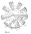
- the prior art drill bit includes a bit body 10 and nine blades 12, 14, 16, 18, 20, 22, 24, 26, and 28 formed on the leading face of the bit and extending outwardly from the axis of the bit body 10 towards to a gauge region 29. Between adjacent blades there are defined channels 30, 32, 34, 36, 38, 40, 42, 44, and 46.
- the cutting structures 48 are of any appropriate type. For example, as shown, they may be circular pre-formed cutting elements brazed to cylindrical carriers which are embedded or otherwise mounted in the blades.
- the cutting elements each may include a pre-formed compact having a polycrystalline diamond front cutting layer bonded to a tungsten carbide substrate, the compact being brazed to a cylindrical tungsten carbide carrier.
- the cutting structure 48 may include the substrate of the pre-formed compact being of sufficient axial length to be mounted directly in the blade, so that the additional carrier may then be omitted.
- Back-up abrasion elements or cutters 49 may be spaced rearwardly of some of the cutting structures, as shown.
- Inner nozzles 50, 52, and 54 are mounted in the surface of the bit body 10 and are located fairly close to the central axis of rotation of the bit. Each inner nozzle 50, 52, and 54 is so located that it can deliver drilling fluid to two or more channels.
- peripheral nozzles 56, 58, and 60 are located in the channels 34, 40, and 44, respectively, and are oriented to direct drilling fluid inwardly along their respective channels towards the center of the drill bit. All of the nozzles communicate with a central axial passage (not shown) in the shank of the bit, to which drilling fluid is supplied under pressure downwardly through the drill string in known manner.
- the outer extremities of the blades 12, 14, 16, 18, 20, 22, 24, 26, and 28 are formed with axially extending kickers 62, 64, 66, 68, 70, 72, 74, 76, and 78, respectively, which provide part-cylindrical bearing surfaces 79 which, in use, bear against the surrounding wall of the borehole and stabilize the bit in the borehole.
- Abrasion-resistant bearing elements 81 may be embedded in the bearing surfaces 79.
- Each of the channels 32, 34, 36, 38, 40, 41, 44, and 46 leads to a respective junk slot 80, 82, 84, 86, 88, 90, 92, and 94.
- the junk slots extend upwardly between the kickers, generally parallel to the central longitudinal axis of the drill bit, so that drilling fluid flowing outwardly along each channel passes into the associated junk slot and flows upwardly, between the bit body and the surrounding formation, into the annulus between the drill string and the wall of the borehole.
- the channel 30 between the blades 12 and 14 does not lead to a conventional junk slot, but continues right up to the gauge region 79 of the drill bit.
- Formed in the channel 30 adjacent the gauge region 79 is a circular opening 96 into an enclosed cylindrical passage 98 which extends through the bit body 10 to an outlet 100 (see Figure 3) which communicates with the annulus.
- the kickers 78 and 62 at the outer extremities of the blades 12 and 14 are connected by an intermediate bearing member 101 that has a bearing surface 102 which extends across the width of the channel 30 so as to form, with the kickers 78 and 62, a large continuous part-cylindrical bearing surface 104.
- a cylindrical socket 106 is formed in the side wall of the passage 98 and is included at an angle to the longitudinal axis of the passage 98.
- a nozzle 108 is mounted in the socket 106 and is angled to direct drilling fluid along the passage 98 towards the opening 96, so that the drilling fluid emerges from the opening 96 and flows inwardly along the channel 30.
- the conventional junk slot is replaced by the enclosed passage 98 which passes internally through the bit body 10.
- This enables the provision on the adjacent part of the gauge region 29 of a bearing surface 104 of extended peripheral extent. This increased bearing surface 104 may enhance the stability of the drill bit in the borehole.
- Fig. 4 shows diagrammatically a typical pattern of flow of drilling fluid over the face of the bit. It will be seen that drilling fluid flows inwardly, as indicated by the arrows, from the peripheral nozzles 108, 56, 58, and 60 towards the center of the bit and then across the face of the bit to flow outwardly along other channels. The outward flow is reinforced by the flow from the inner nozzles 50, 52, and 54.
- the nozzle 108 in the passage 98 may be oriented so as to direct a flow of drilling fluid upwardly through the passage 98 towards the outlet 100, in which case the flow along the channel 30 will be in an outward direction towards the opening 96.
- the nozzle 108 may be omitted altogether, and in this case also drilling fluid will flow outwardly along the channel 30, such flow being derived, for example, from the nozzles 50 and 56.
- Fig. 5 shows an alternative prior art arrangement where the opening 110 into the passage 112 is irregularly shaped so as to extend over almost all of the entire area of the channel 30 between the blades 12 and 14.
- a nozzle is not provided in the passage 112 and the flow of drilling fluid along the channel 30 and through the passage 112 is derived from the peripheral nozzle 56, as indicated by the arrows in Fig. 5.
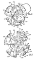
- Figs. 6-8 One form of drill bit according to the present invention is illustrated in Figs. 6-8. Similar to the drill bit illustrated in Figs. 1-5, the drill bit includes a bit body 120 and eight blades 122 formed on the leading face of he bit and extending outwardly from the axis of the bit body towards the gauge region. Between adjacent blades 122 there are defined channels 124.
- Each cutting structure 126 includes a preformed cutting element brazed to a cylindrical carrier which is embedded or otherwise mounted in one of the blades 122.
- Each cutting element may include a preformed compact having a polycrystalline diamond front cutting table which is bonded, by brazing for instance, to a tungsten carbide substrate.
- the substrate of the preformed compact may be of sufficient axially length to be mounted directly in the blade, so that the additional carrier may then be omitted.
- the cutting elements are set with a high back rake of 25 on the nose ofthe drill bit increasing to 40 on the shoulder adjacent the gauge section to reduce the reactive torque.
- the outer region of the drill bit also has increased protection provided by the addition of back-up cutters 130 or abrasion elements 132 disposed rearwardly of the outer three or four cutters on each blade.
- the back-up cutters 130 may have the same exposure as the primary cutters 126, i.e., they may project to the same distance from the surface of the blade on which they are mounted. Alternatively, they may have a higher or a lower exposure.
- the back rake of the back-up cutters 130 may be the same as the primary cutters 126, or they may have a greater or smaller back rake angle.
- each back-up cutter 130 may be located at the same radial position as a corresponding primary cutter 126 so as to follow the groove in the formation cut by its associated primary cutter 126.
- the back-up cutters 130 may be located at radial positions which are intermediate the radial positions of the associated primary cutters, so that each back-up cutter 130 removes from the formation the upstanding kerf left between the two grooves cut by adjacent primary cutters and, thus, provides a smoother surface to the borehole.
- each back-up cutter 130 may be located on the same blade as its associated primary cutter 126, or it may be on a different blade.
- the gauge region 128 of the bit body includes a continuous bearing surface 134 which extends around the whole of the gauge region.
- Gauge protection is provided by inserts 136 which may be a mixture of polycrystalline diamond compacts and diamond inserts. Alternatively, the inserts may be made of tungsten carbide.
- the gauge inserts 136 may be located on those parts ofthe bearing surface 134 which are located at the outer ends of the blades 122, i.e., in areas where the gauge region 29 is fully supported by the bit body 10 radially inwardly of the gauge region 29.
- the gauge inserts 136 act on the formation more aggressively than the intermediate portions of the bearing surface 134 where no inserts are provided. These greater forces are more easily accommodated by the full support of the inserts 136 by the bit body 10, as compared with the relatively unsupported portions of the bearing surface 134 adjacent the openings 140.
- Inner nozzles 138 are mounted in the surface of the bit body and are located fairly close to the central axis of rotation of the bit.
- the inner nozzles 138 are positioned to give efficient cleaning in the central region of the bit and are also directed to deliver drilling fluid along a channel 124 on the leading side of one of the four longer blades 122 on the bit body, so as to clean and cool the cutting elements 126 mounted on that blade.
- the channels 124 between the blades 122 do not lead to conventional junk slots which extend upwardly through the gauge region 128. Rather, the channels 124 continue right up to the continuous bearing surface 134 of the gauge region 128.
- a shaped opening 140 is formed in each channel 124 adjacent the gauge region 128.
- the opening 140 leads to an enclosed passage 142 which extends through the bit body 12 0 to an outlet 144, as illustrated in Fig. 8.
- the passage 142 communicates, in use, with the annulus between the drill string and the surrounding formation forming the walls of the borehole.
- outer nozzles 146 are located in those passages 142 which are disposed on the leading sides of the shorter blades 122. These four outer nozzles 146 are directed to the outer shoulder of the drill bit where a higher proportion of hydraulic energy is required to clean the increased cutter count in this region provided by the back-up cutters 130. Fluid flow from the inner nozzles 138 creates a pressure difference such that fluid from the outer nozzles 146 also flows inwardly towards the inner nozzles 138, across the inner cutters on the shorter blades, before flowing outwardly again with the outward flow from the inner cutters 138.
- Flow from both the inner nozzles 138 and outer nozzles 146 flows to the annulus through the openings 140 and passages 142 through the bit body. All of the nozzles 138 and 146 communicate with a central axial passage (not shown) in the shank of the bit, to which drilling fluid is supplied under pressure downwardly through the drill string in known manner.
- a continuous bearing surface 134 around the whole of the gauge region of the drill bit substantially enhances the stability of the bit in operation. It reduces the bits susceptibility to vibration, due to the absence of edges, cutting elements or other protrusions in the gauge region which otherwise might act on the surrounding formation to cause vibration and, under some circumstances, to initiate "bit whirl".
- the gauge length of the drill bit is considerably less than is normally the case with a conventional PDC drill bit.
- a conventional 12.25 inch drill bit will normally have a gauge of3 to 4 inches in axial length and will normally have an overall length of 12 to 16 inches.
- 6-8 may have a gauge of only 2 inches in axial length and an overall bit length of only 9 inches, thereby not only reducing the axial length of the gauge section but also reducing the distance from the motor to the bit, in a steerable motor-driven system, and thereby improving the directional response of the drill bit when steering is taking place.
- passage 98 is described as being a cylindrical passage parallel to the longitudinal axis of the drill bit, other arrangements are possible.
- the passage may vary in cross-sectional shape and/or diameter along its length. Two or more openings may be provided in the channel, the openings leading to separate passages through the bit body, or two or more openings may lead into a single passage.
- FIG. 9 shows such a lighter set drill bit, according to the invention, where only four blades 148 are provided, separated by channels 150 which are almost 90 in angular extent.
- each channel is formed with two openings 154 and 156 which communicate with separate passages leading through the bit body to the annulus.
- the larger of the two openings 154 is disposed adjacent the gauge section 152 and on the leading side of a respective blade 148, and the smaller opening 156 is disposed adjacent the trailing side of the preceding blade.
- the inner nozzles 158 direct drilling fluid outwardly along the leading edges of the blades 148 respectively.
- the portion 160 of the bit body between each pair of openings 154, 156 may thus be regarded as a support strut which provides radial strength to the gauge section 152 between the widely angularly spaced blades 148.
- FIG. 10 Another embodiment of a drill bit according to the invention is illustrated in Fig. 10.
- This drill bit includes a bit body 162.
- Eight blades 164 are formed on the leading face of the bit. These blades 164 extend generally outwardly from the central axis of the bit body 162 towards a gauge region 165 and, thus, define channels 166 therebetween.
- a plurality of cutting structures 168 which may be similar to the cutting structures described in reference to previous embodiments, extend side- by-side along each of the blades 164.
- the gauge region 165 ofthe bit body 162 includes a continuous bearing surface that extends continuously around the whole of the gauge region 165.
- inner nozzles (not shown) may be mounted in the surface of the bit body, close to the central axis of rotation for instance, to deliver drilling fluid along the channels 166.
- An opening (not shown), similar to the previously described openings, may be formed in each channel 166 adjacent the gauge region 165. Each opening leads to an internal passage that extends through the bit body 162 to an outlet 172.
- the outlet 172 advantageously communicates with the annulus between the drill string and the surrounding formation of the borehole when the drill bit is in use.
- the drill bit of Fig. 10 may also include a portion 174 of the bit body 162 that is relieved.
- the relieved portion 174 includes four breaker slots 176 that are equally spaced about the circumference of the relieved portion 174.
- Each breaker slot 176 may be thought of as a flat-bottomed recess cut into the cylindrical outer surface of the portion 174.
- the breaker slots 176 facilitate tool engagement with the drill bit during attachment or detachment of the tapered threaded pin 178 into an internally threaded collar (not shown) at the lower end of drill string.
- the breaker slots 176 are advantageously in register with one or more outlets 172 to facilitate the flow of drilling fluid as it emerges from the outlets 172 after passing through the internal passages of the drill bit. Specifically, this registration permits the size of the outlets 172 to be maximized to provide a greater flow potential.
- gauge cutters 180 are disposed at the peripheral bearing surface 170 of the gauge region 165.
- the gauge cutters 180 may be mounted in recesses 182 in the bearing surface 170 so that the cutting edges of the gauge cutters 180 project only a short distance from the bearing surface 170.
- two gauge cutters 180 are provided on each portion of the bearing surface 170 which lies at the outer end of a blade 164 on the leading face of the drill bit.
- gauge protection inserts (not shown), similar to the inserts 136 discussed previously, may be disposed in the bearing surface 170.
- a chamfer such as a frusto-conical peripheral chamfer 184, may be formed in the upper edge of the gauge region 165.
- back-reaming cutters 186 may be mounted in a peripherally spaced apart relationship on the upper edge of the gauge region 165. Under particularly difficult conditions, the back-reaming cutters 186 may facilitate removal of the drill bit from the borehole by reaming out the walls of the borehole as the rotating drill bit is withdrawn. In this case, the combination of the back-reaming cutters 186 with the chamfer 184 may increase the exposure of the cutters 186 and, thus, increase their efficiency.
- Figs 11 and 12 illustrate a drill bit having a passage disposed in a first plurality of channels which terminate with a bearing member in the gauge region, and where a second plurality of channels lead to a conventional junk slot. Specifically, channels leading to an internal passage and bearing member are alternated with channels leading to a conventional junk slot.
- the drill bit includes a bit body 188.
- Eight blades 189 are formed on the leading face of the bit and extend generally outwardly from the axis of the bit towards the gauge region 191.
- the blades 189 include four longer blades 190 alternating with four shorter blades 192.
- a plurality of cutting structures 194 extend side-by-side along each of the blades 189.
- Back-up cutters 196 may be provided rearwardly of the primary cutting structures 194 on the shorter blades 192, whereas abrasion elements 198 may be disposed rearwardly of the primary cutting structures 194 on the longer blades 190.
- a channel 200 is defined between the leading edge of each longer blade 190 and the trailing edge of the preceding shorter blade 192.
- Each channel 200 leads outwardly to a junk slot 202 which extends upwardly through the gauge region 191 to the annulus between the drill string and the borehole.
- a channel 204 is defined between the leading edge of each shorter blade 192 and the trailing edge of the preceding longer blade 190.
- an opening 206 is formed in each channel 204 adjacent the gauge region 191.
- Each opening 206 leads to a passage 208 that passes internally through the bit body 188 to an outlet which passes fluid into the annulus between the drill string and the surrounding borehole.
- a bearing member 209 is formed outwardly of each opening 206 between the outer ends of the respective adjacent blades 190 and 192.
- Each bearing member 209 includes a substantially continuous peripheral bearing surface 210 at the gauge region 191.
- the bearing surfaces 210 may also incorporate any of the features previously described with reference to the bearing surfaces of Figs. 11 - 10.
- Inner nozzles 212 are mounted in the surface of the bit body 188 and are located fairly close to the central axis of the bit. The inner nozzles 212 are positioned to provide efficient cleaning in the central region of the bit. The inner nozzles 212 may also be directed to deliver drilling fluid outwardly along each channel 200 along the leading side of one of the four longer blades 190 to clean and cool the cutting elements 194 mounted on that blade.
- An outer nozzle 214 is mounted in a socket in the wall of each internal passage 208 and is directed to cool and clean the outer cutters 194 on the adjacent shorter blade 192. Fluid from each outer nozzle 214 flows both upwardly through the internal passage 206 and also inwardly towards the adjacent inner nozzle 212 to cool and clean the inner cutters on the shorter blades 192. This inwardly directed fluid then becomes entrained with the fluid flowing outwardly from the adjacent inner nozzle 212 so that it flows outwardly through the rearwardly adjacent channel 200 leading to a junk slot 202. The flow of drilling fluid is illustrated by arrows in Fig. 12.
- the junk slots 202 extend substantially parallel to the longitudinal axis of the bit body 188.
- the junk slots may extend helically with respect to the longitudinal axis so that the upper extremity of the bearing surface 210 on one side of the junk slot 202 approaches or overlaps the circumferential position of the lower extremity of the bearing surface 210 on the other side of the junk slot.
- Such arrangement may then provide that there is a portion of the bearing surface 210 around substantially the whole 360 degree periphery of the gauge region 191.
Landscapes
- Engineering & Computer Science (AREA)
- Life Sciences & Earth Sciences (AREA)
- Geology (AREA)
- Mining & Mineral Resources (AREA)
- Mechanical Engineering (AREA)
- Physics & Mathematics (AREA)
- Environmental & Geological Engineering (AREA)
- Fluid Mechanics (AREA)
- General Life Sciences & Earth Sciences (AREA)
- Geochemistry & Mineralogy (AREA)
- Earth Drilling (AREA)
Applications Claiming Priority (2)
| Application Number | Priority Date | Filing Date | Title |
|---|---|---|---|
| US08/834,439 US6089336A (en) | 1995-10-10 | 1997-04-16 | Rotary drill bits |
| US834439 | 1997-04-16 |
Publications (3)
| Publication Number | Publication Date |
|---|---|
| EP0872625A2 true EP0872625A2 (fr) | 1998-10-21 |
| EP0872625A3 EP0872625A3 (fr) | 2000-04-05 |
| EP0872625B1 EP0872625B1 (fr) | 2005-11-16 |
Family
ID=25266947
Family Applications (1)
| Application Number | Title | Priority Date | Filing Date |
|---|---|---|---|
| EP98302826A Expired - Lifetime EP0872625B1 (fr) | 1997-04-16 | 1998-04-09 | Trépans de forage rotatif avec buses |
Country Status (4)
| Country | Link |
|---|---|
| US (1) | US6089336A (fr) |
| EP (1) | EP0872625B1 (fr) |
| DE (1) | DE69832318T2 (fr) |
| GB (1) | GB2326656B (fr) |
Cited By (6)
| Publication number | Priority date | Publication date | Assignee | Title |
|---|---|---|---|---|
| EP1227214A3 (fr) * | 2001-01-27 | 2003-03-19 | Camco International (UK) Limited | Structure de coupe pour trépan de forage |
| WO2007098159A2 (fr) * | 2006-02-23 | 2007-08-30 | Baker Hughes Incorporated | Insert d'élément de coupe de dispositifs de coupe de réserve dans des trépans rotatifs, trépans rotatifs équipés d'un tel insert, et procédés de fabrication correspondants |
| WO2008092113A2 (fr) * | 2007-01-25 | 2008-07-31 | Baker Hughes Incorporated | Trépan à lames rotatif et procédés associés |
| WO2009140006A1 (fr) * | 2008-05-12 | 2009-11-19 | Baker Hughes Incorporated | Fraise à flux inversé |
| US7896106B2 (en) | 2006-12-07 | 2011-03-01 | Baker Hughes Incorporated | Rotary drag bits having a pilot cutter configuraton and method to pre-fracture subterranean formations therewith |
| EP2904183A4 (fr) * | 2012-10-02 | 2016-06-22 | Varel Int Ind Lp | Dispositif de mesure à écoulement traversant pour trépan de forage |
Families Citing this family (28)
| Publication number | Priority date | Publication date | Assignee | Title |
|---|---|---|---|---|
| US20020043404A1 (en) * | 1997-06-06 | 2002-04-18 | Robert Trueman | Erectable arm assembly for use in boreholes |
| US6125947A (en) | 1997-09-19 | 2000-10-03 | Baker Hughes Incorporated | Earth-boring drill bits with enhanced formation cuttings removal features and methods of drilling |
| GB9906114D0 (en) | 1999-03-18 | 1999-05-12 | Camco Int Uk Ltd | A method of applying a wear-resistant layer to a surface of a downhole component |
| SE524046C2 (sv) | 1999-09-24 | 2004-06-22 | Varel Internat Inc | Rullborrkrona |
| AU2001276505A1 (en) * | 2000-08-23 | 2002-03-04 | Schlumberger Canada Limited | Method of mounting a tsp |
| US6408958B1 (en) * | 2000-10-23 | 2002-06-25 | Baker Hughes Incorporated | Superabrasive cutting assemblies including cutters of varying orientations and drill bits so equipped |
| CN1280516C (zh) * | 2000-11-27 | 2006-10-18 | 国际壳牌研究有限公司 | 钻孔钻头 |
| US6568492B2 (en) | 2001-03-02 | 2003-05-27 | Varel International, Inc. | Drag-type casing mill/drill bit |
| AUPR886401A0 (en) * | 2001-11-14 | 2001-12-06 | Cmte Development Limited | Fluid drilling head |
| AU2002952176A0 (en) | 2002-10-18 | 2002-10-31 | Cmte Development Limited | Drill head steering |
| US6920084B2 (en) * | 2003-01-15 | 2005-07-19 | Western Geco, L.L.C. | Offset transformation to zero dip that preserves angle of incidence |
| AT500169A1 (de) * | 2003-10-16 | 2005-11-15 | Boehlerit Gmbh & Co Kg | Reibahle |
| CA2538545C (fr) | 2005-03-03 | 2013-01-15 | Sidney J. Isnor | Foret de coupe fixe pour applications d'abrasion |
| US8047309B2 (en) * | 2007-03-14 | 2011-11-01 | Baker Hughes Incorporated | Passive and active up-drill features on fixed cutter earth-boring tools and related systems and methods |
| US20090084607A1 (en) * | 2007-10-01 | 2009-04-02 | Ernst Stephen J | Drill bits and tools for subterranean drilling |
| US20090084606A1 (en) * | 2007-10-01 | 2009-04-02 | Doster Michael L | Drill bits and tools for subterranean drilling |
| US20100025121A1 (en) * | 2008-07-30 | 2010-02-04 | Thorsten Schwefe | Earth boring drill bits with using opposed kerfing for cutters |
| US20100078223A1 (en) * | 2008-09-26 | 2010-04-01 | Buske Robert J | Plate structure for earth-boring tools, tools including plate structures and methods of forming such tools |
| US8505634B2 (en) * | 2009-12-28 | 2013-08-13 | Baker Hughes Incorporated | Earth-boring tools having differing cutting elements on a blade and related methods |
| CA2788816C (fr) * | 2010-02-05 | 2015-11-24 | Baker Hughes Incorporated | Elements de coupe profiles sur des trepans et autres outils de forage, et procedes de formation de tels elements |
| US8851207B2 (en) | 2011-05-05 | 2014-10-07 | Baker Hughes Incorporated | Earth-boring tools and methods of forming such earth-boring tools |
| SA111320671B1 (ar) | 2010-08-06 | 2015-01-22 | بيكر هوغيس انكور | عوامل القطع المشكلة لادوات ثقب الارض و ادوات ثقب الارض شاملة عوامل القطع هذه و الطرق المختصة بها |
| EP2812523B1 (fr) | 2012-02-08 | 2019-08-07 | Baker Hughes, a GE company, LLC | Éléments de coupe profilés pour outils de forage et outils de forage comprenant lesdits éléments de coupe |
| US9464490B2 (en) * | 2012-05-03 | 2016-10-11 | Smith International, Inc. | Gage cutter protection for drilling bits |
| EP2872723A4 (fr) * | 2012-07-13 | 2016-01-27 | Halliburton Energy Services Inc | Trépans de forage rotatifs avec éléments de coupe de secours pour optimiser une durée de vie de trépan |
| CA2929078C (fr) | 2013-12-06 | 2018-07-17 | Halliburton Energy Services, Inc. | Trepan rotatif comprenant des elements de coupe multicouche |
| MX2017008848A (es) * | 2015-02-09 | 2017-10-24 | Halliburton Energy Services Inc | Cubierta para elementos electronicos del centralizador. |
| US9981406B2 (en) | 2015-06-25 | 2018-05-29 | Black & Decker Inc. | Drill bit |
Citations (1)
| Publication number | Priority date | Publication date | Assignee | Title |
|---|---|---|---|---|
| EP0707132A2 (fr) | 1994-10-15 | 1996-04-17 | Camco Drilling Group Limited | Trépan de forage rotatif |
Family Cites Families (12)
| Publication number | Priority date | Publication date | Assignee | Title |
|---|---|---|---|---|
| GB1348694A (en) * | 1971-05-10 | 1974-03-20 | Shell Int Research | Diamond bit |
| US4440247A (en) * | 1982-04-29 | 1984-04-03 | Sartor Raymond W | Rotary earth drilling bit |
| CA1217475A (fr) * | 1982-09-16 | 1987-02-03 | John D. Barr | Trepan de forage |
| US4512425A (en) * | 1983-02-22 | 1985-04-23 | Christensen, Inc. | Up-drill sub for use in rotary drilling |
| GB8524146D0 (en) * | 1985-10-01 | 1985-11-06 | Nl Petroleum Prod | Rotary drill bits |
| EP0295045A3 (fr) * | 1987-06-09 | 1989-10-25 | Reed Tool Company | Trépan racleur rotatif avec des buses de nettoyage |
| US5145017A (en) * | 1991-01-07 | 1992-09-08 | Exxon Production Research Company | Kerf-cutting apparatus for increased drilling rates |
| US5199511A (en) * | 1991-09-16 | 1993-04-06 | Baker-Hughes, Incorporated | Drill bit and method for reducing formation fluid invasion and for improved drilling in plastic formations |
| US5467836A (en) * | 1992-01-31 | 1995-11-21 | Baker Hughes Incorporated | Fixed cutter bit with shear cutting gage |
| AU5850694A (en) * | 1992-12-23 | 1994-07-19 | Baroid Technology, Inc. | Drill bit having chip breaker polycrystalline diamond compact and hard metal insert at gauge surface |
| GB2294070B (en) * | 1994-10-15 | 1998-04-22 | Camco Drilling Group Ltd | Improvements in or relating to rotary drill bits |
| US5794725A (en) * | 1996-04-12 | 1998-08-18 | Baker Hughes Incorporated | Drill bits with enhanced hydraulic flow characteristics |
-
1997
- 1997-04-16 US US08/834,439 patent/US6089336A/en not_active Expired - Lifetime
-
1998
- 1998-04-09 EP EP98302826A patent/EP0872625B1/fr not_active Expired - Lifetime
- 1998-04-09 GB GB9807553A patent/GB2326656B/en not_active Expired - Lifetime
- 1998-04-09 DE DE69832318T patent/DE69832318T2/de not_active Expired - Lifetime
Patent Citations (1)
| Publication number | Priority date | Publication date | Assignee | Title |
|---|---|---|---|---|
| EP0707132A2 (fr) | 1994-10-15 | 1996-04-17 | Camco Drilling Group Limited | Trépan de forage rotatif |
Cited By (12)
| Publication number | Priority date | Publication date | Assignee | Title |
|---|---|---|---|---|
| EP1227214A3 (fr) * | 2001-01-27 | 2003-03-19 | Camco International (UK) Limited | Structure de coupe pour trépan de forage |
| WO2007098159A2 (fr) * | 2006-02-23 | 2007-08-30 | Baker Hughes Incorporated | Insert d'élément de coupe de dispositifs de coupe de réserve dans des trépans rotatifs, trépans rotatifs équipés d'un tel insert, et procédés de fabrication correspondants |
| WO2007098159A3 (fr) * | 2006-02-23 | 2007-10-04 | Baker Hughes Inc | Insert d'élément de coupe de dispositifs de coupe de réserve dans des trépans rotatifs, trépans rotatifs équipés d'un tel insert, et procédés de fabrication correspondants |
| US7896106B2 (en) | 2006-12-07 | 2011-03-01 | Baker Hughes Incorporated | Rotary drag bits having a pilot cutter configuraton and method to pre-fracture subterranean formations therewith |
| WO2008092113A2 (fr) * | 2007-01-25 | 2008-07-31 | Baker Hughes Incorporated | Trépan à lames rotatif et procédés associés |
| WO2008092113A3 (fr) * | 2007-01-25 | 2008-09-12 | Baker Hughes Inc | Trépan à lames rotatif et procédés associés |
| WO2008091654A3 (fr) * | 2007-01-25 | 2008-09-18 | Baker Hughes Inc | Trépan à lame rotative |
| US7762355B2 (en) | 2007-01-25 | 2010-07-27 | Baker Hughes Incorporated | Rotary drag bit and methods therefor |
| US7861809B2 (en) | 2007-01-25 | 2011-01-04 | Baker Hughes Incorporated | Rotary drag bit with multiple backup cutters |
| WO2009140006A1 (fr) * | 2008-05-12 | 2009-11-19 | Baker Hughes Incorporated | Fraise à flux inversé |
| GB2474148A (en) * | 2008-05-12 | 2011-04-06 | Baker Hughes Inc | Reverse flow mill |
| EP2904183A4 (fr) * | 2012-10-02 | 2016-06-22 | Varel Int Ind Lp | Dispositif de mesure à écoulement traversant pour trépan de forage |
Also Published As
| Publication number | Publication date |
|---|---|
| GB2326656B (en) | 2001-12-12 |
| US6089336A (en) | 2000-07-18 |
| DE69832318T2 (de) | 2006-08-10 |
| DE69832318D1 (de) | 2005-12-22 |
| EP0872625B1 (fr) | 2005-11-16 |
| GB2326656A (en) | 1998-12-30 |
| GB9807553D0 (en) | 1998-06-10 |
| EP0872625A3 (fr) | 2000-04-05 |
Similar Documents
| Publication | Publication Date | Title |
|---|---|---|
| EP0872625B1 (fr) | Trépans de forage rotatif avec buses | |
| EP0884449B1 (fr) | Trépan de forage rotatif | |
| EP0872624B1 (fr) | Perfectionnements aux trépans de forage rotatifs | |
| US6062325A (en) | Rotary drill bits | |
| EP0707132B1 (fr) | Trépan de forage rotatif | |
| US7059430B2 (en) | Hydro-lifter rock bit with PDC inserts | |
| EP0710765B1 (fr) | Perfectionnements relatifs aux trépans de forage rotatifs | |
| EP1794406B1 (fr) | Fleuret de perforatrice | |
| EP0974730B1 (fr) | Trépan racleur | |
| US20060278442A1 (en) | Drill bit | |
| EP0624708B1 (fr) | Arrangement de buses pour trépan racleur | |
| EP0171915B1 (fr) | Trépans de forage | |
| EP0898044B1 (fr) | Trépan racleur rotatif avec buses pour fluide de forage | |
| GB2294070A (en) | Rotary drill bit with enclosed fluid passage | |
| GB2361496A (en) | Placement of primary and secondary cutters on rotary drill bit | |
| KR20210049810A (ko) | 만곡된 슬러지 그루브들을 갖는 드릴 비트 | |
| GB2359838A (en) | Rotary drill bit | |
| CA2510136A1 (fr) | Trepan |
Legal Events
| Date | Code | Title | Description |
|---|---|---|---|
| PUAI | Public reference made under article 153(3) epc to a published international application that has entered the european phase |
Free format text: ORIGINAL CODE: 0009012 |
|
| AK | Designated contracting states |
Kind code of ref document: A2 Designated state(s): BE DE FR NL |
|
| AX | Request for extension of the european patent |
Free format text: AL;LT;LV;MK;RO;SI |
|
| PUAL | Search report despatched |
Free format text: ORIGINAL CODE: 0009013 |
|
| RIC1 | Information provided on ipc code assigned before grant |
Free format text: 7E 21B 10/60 A, 7E 21B 10/54 B, 7E 21B 10/26 B |
|
| AK | Designated contracting states |
Kind code of ref document: A3 Designated state(s): AT BE CH CY DE DK ES FI FR GB GR IE IT LI LU MC NL PT SE |
|
| AX | Request for extension of the european patent |
Free format text: AL;LT;LV;MK;RO;SI |
|
| 17P | Request for examination filed |
Effective date: 20000623 |
|
| AKX | Designation fees paid |
Free format text: BE DE FR NL |
|
| 17Q | First examination report despatched |
Effective date: 20030911 |
|
| GRAP | Despatch of communication of intention to grant a patent |
Free format text: ORIGINAL CODE: EPIDOSNIGR1 |
|
| GRAS | Grant fee paid |
Free format text: ORIGINAL CODE: EPIDOSNIGR3 |
|
| GRAA | (expected) grant |
Free format text: ORIGINAL CODE: 0009210 |
|
| AK | Designated contracting states |
Kind code of ref document: B1 Designated state(s): BE DE FR NL |
|
| PG25 | Lapsed in a contracting state [announced via postgrant information from national office to epo] |
Ref country code: NL Free format text: LAPSE BECAUSE OF FAILURE TO SUBMIT A TRANSLATION OF THE DESCRIPTION OR TO PAY THE FEE WITHIN THE PRESCRIBED TIME-LIMIT Effective date: 20051116 |
|
| REF | Corresponds to: |
Ref document number: 69832318 Country of ref document: DE Date of ref document: 20051222 Kind code of ref document: P |
|
| NLV1 | Nl: lapsed or annulled due to failure to fulfill the requirements of art. 29p and 29m of the patents act | ||
| PGFP | Annual fee paid to national office [announced via postgrant information from national office to epo] |
Ref country code: BE Payment date: 20060619 Year of fee payment: 9 |
|
| PLBE | No opposition filed within time limit |
Free format text: ORIGINAL CODE: 0009261 |
|
| STAA | Information on the status of an ep patent application or granted ep patent |
Free format text: STATUS: NO OPPOSITION FILED WITHIN TIME LIMIT |
|
| 26N | No opposition filed |
Effective date: 20060817 |
|
| EN | Fr: translation not filed | ||
| BERE | Be: lapsed |
Owner name: *CAMCO INTERNATIONAL (UK) LTD Effective date: 20070430 |
|
| PG25 | Lapsed in a contracting state [announced via postgrant information from national office to epo] |
Ref country code: FR Free format text: LAPSE BECAUSE OF FAILURE TO SUBMIT A TRANSLATION OF THE DESCRIPTION OR TO PAY THE FEE WITHIN THE PRESCRIBED TIME-LIMIT Effective date: 20070105 |
|
| PG25 | Lapsed in a contracting state [announced via postgrant information from national office to epo] |
Ref country code: BE Free format text: LAPSE BECAUSE OF NON-PAYMENT OF DUE FEES Effective date: 20070430 |
|
| PG25 | Lapsed in a contracting state [announced via postgrant information from national office to epo] |
Ref country code: FR Free format text: LAPSE BECAUSE OF FAILURE TO SUBMIT A TRANSLATION OF THE DESCRIPTION OR TO PAY THE FEE WITHIN THE PRESCRIBED TIME-LIMIT Effective date: 20051116 |
|
| PGFP | Annual fee paid to national office [announced via postgrant information from national office to epo] |
Ref country code: DE Payment date: 20170404 Year of fee payment: 20 |
|
| REG | Reference to a national code |
Ref country code: DE Ref legal event code: R071 Ref document number: 69832318 Country of ref document: DE |