EP0872418B1 - Ausfallsichere Triebwerksaufhängung durch drei Gestänge mit drei Hebeln - Google Patents
Ausfallsichere Triebwerksaufhängung durch drei Gestänge mit drei HebelnInfo
- Publication number
- EP0872418B1 EP0872418B1 EP98201087A EP98201087A EP0872418B1 EP 0872418 B1 EP0872418 B1 EP 0872418B1 EP 98201087 A EP98201087 A EP 98201087A EP 98201087 A EP98201087 A EP 98201087A EP 0872418 B1 EP0872418 B1 EP 0872418B1
- Authority
- EP
- European Patent Office
- Prior art keywords
- link
- engine
- clevis
- engine mount
- upper fitting
- Prior art date
- Legal status (The legal status is an assumption and is not a legal conclusion. Google has not performed a legal analysis and makes no representation as to the accuracy of the status listed.)
- Expired - Lifetime
Links
- 241000256259 Noctuidae Species 0.000 description 4
- 230000008602 contraction Effects 0.000 description 3
- 238000012986 modification Methods 0.000 description 3
- 230000004048 modification Effects 0.000 description 3
- 229910001200 Ferrotitanium Inorganic materials 0.000 description 2
- RTAQQCXQSZGOHL-UHFFFAOYSA-N Titanium Chemical compound [Ti] RTAQQCXQSZGOHL-UHFFFAOYSA-N 0.000 description 2
- 229910001026 inconel Inorganic materials 0.000 description 2
- 238000004513 sizing Methods 0.000 description 2
- 229910001220 stainless steel Inorganic materials 0.000 description 2
- 239000010935 stainless steel Substances 0.000 description 2
- 239000010936 titanium Substances 0.000 description 2
- 230000003466 anti-cipated effect Effects 0.000 description 1
- 230000000712 assembly Effects 0.000 description 1
- 238000000429 assembly Methods 0.000 description 1
- 238000005452 bending Methods 0.000 description 1
- 230000000694 effects Effects 0.000 description 1
- 238000003754 machining Methods 0.000 description 1
- 239000000463 material Substances 0.000 description 1
- 239000013598 vector Substances 0.000 description 1
Images


Classifications
-
- F—MECHANICAL ENGINEERING; LIGHTING; HEATING; WEAPONS; BLASTING
- F02—COMBUSTION ENGINES; HOT-GAS OR COMBUSTION-PRODUCT ENGINE PLANTS
- F02C—GAS-TURBINE PLANTS; AIR INTAKES FOR JET-PROPULSION PLANTS; CONTROLLING FUEL SUPPLY IN AIR-BREATHING JET-PROPULSION PLANTS
- F02C7/00—Features, components parts, details or accessories, not provided for in, or of interest apart form groups F02C1/00 - F02C6/00; Air intakes for jet-propulsion plants
- F02C7/20—Mounting or supporting of plant; Accommodating heat expansion or creep
-
- B—PERFORMING OPERATIONS; TRANSPORTING
- B64—AIRCRAFT; AVIATION; COSMONAUTICS
- B64D—EQUIPMENT FOR FITTING IN OR TO AIRCRAFT; FLIGHT SUITS; PARACHUTES; ARRANGEMENT OR MOUNTING OF POWER PLANTS OR PROPULSION TRANSMISSIONS IN AIRCRAFT
- B64D27/00—Arrangement or mounting of power plants in aircraft; Aircraft characterised by the type or position of power plants
- B64D27/02—Aircraft characterised by the type or position of power plants
- B64D27/16—Aircraft characterised by the type or position of power plants of jet type
- B64D27/18—Aircraft characterised by the type or position of power plants of jet type within, or attached to, wings
-
- B—PERFORMING OPERATIONS; TRANSPORTING
- B64—AIRCRAFT; AVIATION; COSMONAUTICS
- B64D—EQUIPMENT FOR FITTING IN OR TO AIRCRAFT; FLIGHT SUITS; PARACHUTES; ARRANGEMENT OR MOUNTING OF POWER PLANTS OR PROPULSION TRANSMISSIONS IN AIRCRAFT
- B64D27/00—Arrangement or mounting of power plants in aircraft; Aircraft characterised by the type or position of power plants
- B64D27/40—Arrangements for mounting power plants in aircraft
- B64D27/402—Arrangements for mounting power plants in aircraft comprising box like supporting frames, e.g. pylons or arrangements for embracing the power plant
-
- B—PERFORMING OPERATIONS; TRANSPORTING
- B64—AIRCRAFT; AVIATION; COSMONAUTICS
- B64D—EQUIPMENT FOR FITTING IN OR TO AIRCRAFT; FLIGHT SUITS; PARACHUTES; ARRANGEMENT OR MOUNTING OF POWER PLANTS OR PROPULSION TRANSMISSIONS IN AIRCRAFT
- B64D27/00—Arrangement or mounting of power plants in aircraft; Aircraft characterised by the type or position of power plants
- B64D27/40—Arrangements for mounting power plants in aircraft
- B64D27/404—Suspension arrangements specially adapted for supporting vertical loads
-
- B—PERFORMING OPERATIONS; TRANSPORTING
- B64—AIRCRAFT; AVIATION; COSMONAUTICS
- B64D—EQUIPMENT FOR FITTING IN OR TO AIRCRAFT; FLIGHT SUITS; PARACHUTES; ARRANGEMENT OR MOUNTING OF POWER PLANTS OR PROPULSION TRANSMISSIONS IN AIRCRAFT
- B64D27/00—Arrangement or mounting of power plants in aircraft; Aircraft characterised by the type or position of power plants
- B64D27/40—Arrangements for mounting power plants in aircraft
- B64D27/406—Suspension arrangements specially adapted for supporting thrust loads, e.g. thrust links
-
- Y—GENERAL TAGGING OF NEW TECHNOLOGICAL DEVELOPMENTS; GENERAL TAGGING OF CROSS-SECTIONAL TECHNOLOGIES SPANNING OVER SEVERAL SECTIONS OF THE IPC; TECHNICAL SUBJECTS COVERED BY FORMER USPC CROSS-REFERENCE ART COLLECTIONS [XRACs] AND DIGESTS
- Y02—TECHNOLOGIES OR APPLICATIONS FOR MITIGATION OR ADAPTATION AGAINST CLIMATE CHANGE
- Y02T—CLIMATE CHANGE MITIGATION TECHNOLOGIES RELATED TO TRANSPORTATION
- Y02T50/00—Aeronautics or air transport
- Y02T50/40—Weight reduction
-
- Y—GENERAL TAGGING OF NEW TECHNOLOGICAL DEVELOPMENTS; GENERAL TAGGING OF CROSS-SECTIONAL TECHNOLOGIES SPANNING OVER SEVERAL SECTIONS OF THE IPC; TECHNICAL SUBJECTS COVERED BY FORMER USPC CROSS-REFERENCE ART COLLECTIONS [XRACs] AND DIGESTS
- Y02—TECHNOLOGIES OR APPLICATIONS FOR MITIGATION OR ADAPTATION AGAINST CLIMATE CHANGE
- Y02T—CLIMATE CHANGE MITIGATION TECHNOLOGIES RELATED TO TRANSPORTATION
- Y02T50/00—Aeronautics or air transport
- Y02T50/60—Efficient propulsion technologies, e.g. for aircraft
Definitions
- This present invention relates to a failsafe engine mount for attaching an engine casing of a jet engine to a support structure on an airplane, comprising:
- Such a failsafe engine mount is known from EP-A-0741074.
- Airplane engines are typically mounted below an aircraft wing or near the tail section by an engine mount. Mounts are usually provided for both the forward portion of the engine and the aft portion of the engine, so as to distribute the engine load.
- Typical engine mounts include several components. One of the components is a generally planar upper fitting that has a mounting platform located along its upper edge that is used to attach the engine mount to a support structure of the aircraft, e.g., a wing strut or tail pylon. Multiple devises are located on the lower edge of the upper fitting and also along a portion of an engine casing. Multiple links, pinned in the clevises of both the upper fitting and the engine casing, connect the engine to the support structure. Similar engine mounts of this type are used at both the forward and aft portions of the engine.
- Engine mounts are designed to handle a variety of loads, during all phases of flight.
- the loads include vertical loads (the weight of the engine plus maneuver loads), axial loads (caused by the engine's thrust), side loads (caused by wind buffeting, for example), and torsion loads (caused by the rotary operation of the engine, or by the loss of a turbine blade).
- An engine mount must also accommodate thermal expansion and contraction of the engine relative to the mount. The effect of thermal expansion and contraction is most significant during cruise phase. During cruise, thermal expansion and contraction can cause an appreciable shift in the direction of loads acting on an engine mount.
- Failsafe operation is provided by a secondary, or backup, load-carrying system.
- Two types of secondary systems are common.
- the first type utilizes components of the thrust reverser (such as the translating cowl) to carry engine loads.
- the second type utilizes catcher links placed within the engine mount itself.
- Catcher links are additional links in the engine mount that are typically unloaded during normal operation. Should a primary (i.e., non-catcher) link fail, the catcher links are capable of cooperating with the remaining unfailed links to carry engine loads.
- Link failures may result from many causes, including failure of pins or devises; broken, deformed, missing, or mis-installed links; sheared pins; etc.
- the thrust reverser system is the more widely used approach.
- the use of catcher links is a more efficient solution, because they require relatively much less weight and space.
- relatively few catcher link engine mounts are known, and of these, not many describe three-link systems.
- Applicant's earlier patent application EP-A-0 741 074 already describes a three link failsafe engine mount including an upper fitting that is attached to a support structure, e.g. a pylon suspended from the wing of an aircraft, and a clevis strip attached to the engine casing.
- Three links connect the clevis strip to the upper fitting, both of which include four connection locations.
- the first of the three links, an outer link, is straight, whereas the other two links are dog leg shaped.
- the middle dog leg link has its two outer ends connected to the two middle connection locations on the clevis strip, and its corner connected to the second of the connection locations in the upper fitting.
- the outer end connected to the third connection location on the clevis strip is connected thereto with play, such as to be unloaded under normal flight conditions.
- the dog leg third or outer link has one end connected to the fourth connection location in the clevis strip and its corner connected to the fourth connection location in the upper fitting. The other end of the dog leg outer link is connected with play to the third connection location of the upper fitting. All connections are by means of pin-and-clevis joints.
- an improved failsafe engine mount for attaching a jet engine to an aircraft support structure, which efficiently distributes engine loads among several of the mount links during normal operation, as well as among the remaining links during a single link failure.
- the failsafe engine mount of the present invention is distinguished from the above-discussed prior art engine mount in that the third link includes a peg extending from an upper region of the third link, the peg being insertable into a hole formed in the upper fitting.
- Engine mounts formed in accordance with the invention can be attached to various locations on an airplane (e.g., under the wing or to the tail section) or on'an engine (e.g., at the forward portion of the engine or at the aft portion of the engine), with only slight modification to the sizings of the mount components being required.
- the first and third links carry the majority of the vertical loads, while the first arm of the second link carries most of the horizontal loads. Torsion loads are shared by all three links. If the first link fails, the second arm of the second link works to absorb some of the load previously carried by the first link.
- the peg of the third link and hole in the upper fitting can be sized and positioned to be unloaded during normal airplane operations and during a failure of the first link.
- the peg and the upper fitting hole can be arranged to work with the first link to carry the engine loads should the second link fail.
- the peg of the third link is cross-sectionally ovoid in shape and the space between the peg exterior surfaces and the upper fitting hole surface during normal operations is in the range of about 2.54 mm (0.100 inches) to about 7.62 mm (0.300 inches), a preferred distance being about 6.4 mm (0.25 inch).
- the present invention provides a new and distinctly better engine mount. If any link fails, the vertical, horizontal, and torsion loads once carried by the failed link are efficiently distributed among the remaining links.
- the entire engine mount is relatively compact, thus making optimal use of the limited amount of space available in jet airplanes and providing greater ground clearance if used on an underwing engine.
- the present invention has a relatively wide load-couple during a failed link condition.
- the links are configured so that during normal operations the catcher links are unloaded, which eliminates unnecessary wear. In addition, there are no loose links to vibrate, thus component wear is reduced.
- FIGURE 1 is a side schematic view of a conventional aircraft jet engine 11 supported by a pylon 17 located below an aircraft wing.
- the engine 11 is attached to the pylon 17 by an engine mount 19 formed in accordance with the present invention. More specifically, the engine mount 19 is attached to an aft portion of the engine 11 near the turbine rear frame 21.
- the engine mount 19 depicted in FIGURE 1 is an aft engine mount.
- FIGURE 1 illustrates an aft engine mount
- engine mounts formed in accordance with the teachings of the present invention may be used in a variety of engine mounting locations. For example, they can be used as a forward or aft mount, or both. They can be used to mount the engine either under the wing or to the tail section of the aircraft.
- FIGURE 1 is meant to be illustrative, not limiting. In this regard, the following written description of a specific engine mount for use in the position shown in FIGURE 1 should also be considered as illustrative and not limiting.
- the precise position selected to use an engine mount formed in accordance with the present invention may require modification of the sizings of the mount components for that particular application. These modifications depend upon a variety of factors known to those skilled in the art of engine mounting, e.g., engine size, anticipated loads, aerodynamic considerations, etc.
- FIGURE 2 is a rear view of a prior art failsafe engine mount disclosed in EP-A-0 741 074 and suitable for use as in FIGURE 1, as seen by an observer standing behind the engine 11.
- the engine mount 19 includes an upper fitting 31 and three links 45, 47, 53.
- the upper fitting 31 is attached to the pylon 17 (shown in FIGURE 1) or some other airplane support structure.
- the links 45, 47, 53 are arranged to connect four connection locations 39a, 39b, 39c, 39d on the upper fitting 31 with four connection locations 75a, 75b, 75c, 75d on a clevis strip 73 which is attached to an engine casing 71 (shown in FIGURE 5).
- Attachments of the links 45, 47, 53 to the upper fitting 31 and to the engine casing 71 at the various connection locations are accomplished using pin-and-clevis joints.
- the links 45, 47, 53 support the vertical and horizontal/torsion loads of the engine 11. Should a link fail, the remaining links are arranged to completely assume the loads previously carried by the failed link.
- the material used for the upper fitting 31, links 45, 47, 53, pins and clevises should be preferably Inconel, titanium, or stainless steel.
- the upper fitting 31 has a mounting platform 33 formed along an upper surface for attaching the engine mount 19 to the pylon 17.
- the mounting platform 33 includes a plurality of bolt holes for accepting a bolt arrangement (not shown) that attaches the platform 33 to the pylon 17. The bolts transfer the vertical loads carried by the aft engine mount 19 to the pylon 17.
- the mounting platform 33 also includes one or more shear pin bores for accepting a shear pin arrangement (not shown) that also attaches the platform to the pylon 17. The shear pin arrangement transfers the side and thrust loads carried by the aft engine mount 19 to the pylon 17.
- the upper fitting 31 further includes a short rib section located below the mounting platform.
- the rib section includes structurally reinforced areas, or ribs 35, that carry engine loads between the mounting platform 33 and the links 45, 47, 53.
- the ribs 35 aid in controlling the alignment of the force vectors created by engine loads. Sufficient numbers of ribs 35 are included to ensure that the engine loads are fully supported. Because engine loads are transmitted primarily along the ribs 35, the areas in-between the ribs may be pocketed to reduce the weight of the upper fitting 31.
- the embodiments of the FIGURES show a rib section that is relatively compact, the height of the rib section may be increased in ways apparent to those skilled in the art, to allow an engine vibration isolator to be installed, should the need arise.
- each upper connection location includes a clevis 41 with a pin hole 44a, 44b bored through each of two tines 42a, 42b of the clevis.
- each of the links 45, 47, 53 is positioned between the clevis tines 42a, 42b and is held in place by a clevis pin 43 that passes through the pin hole 44a in one of the clevis tines 42a, through a hole 61 in the end of the link, and then through the pin hole 44b in other clevis tine 42b. This arrangement is described in further detail below.
- the contour of the lower edge of the upper fitting 31 is preferably determined by connecting lower arcs formed about each clevis pin hole, with simple curves.
- the lower arcs are formed by rotating a radius at each pin hole that is larger than the radius of the pin hole. Care should be taken to allow sufficient structure in the clevis tines 42a, 42b around each of the clevis pin holes 44a, 44b to carry the expected loads.
- the clevises 41 are formed by machining, preferably, Inconel, titanium, or stainless steel; and are shaped such that the ends of the links 45, 47, 53 will fit easily into their respective clevises 41 during all phases of flight. Care should be taken to ensure that adequate space for the links is available during both normal and failed-link operations, as discussed below.
- the clevis strip 73 is located along the radial upper edge of the engine case 71.
- the clevis strip 73 lies in a plane generally transverse to the longitudinal axis 13 of the engine 11, generally inline with the plane formed by the upper connection locations.
- the clevis strip 73 contains four lower connection locations: one 75a for the first link 45; two 75b, 75c for the second link 470; and one 75d for the third link 53.
- Each lower connection location 75a, 75b, 75c, 75d includes a clevis 41 with a clevis pin hole 44a, 44b bored through each of the tines 42a, 42b of the clevis (as shown in FIGURE 4).
- the other ends of the links 45, 47, 53 are each positioned between the tines 42a, 42b of a clevis and are held in place by inserting clevis pins 43 through both the tines 42a, 42b of the related clevis and through a hole 61 in the end of the link.
- the outer contour of the clevis strip 73 is determined by connecting lower arcs formed about each clevis pin hole, with simple curves. The lower arcs are formed by rotating a radius at each pin hole 44a, 44b that is larger than the radius of the pin hole. Care should be taken to allow sufficient structure around each of the clevis pin holes 44a, 44b to carry the expected loads.
- the first aspect is the general shape and location of the links relative to the upper fitting 31 and to the engine casing 71.
- the second aspect is the use of pin-and-clevis joints to attach the links to the upper fitting 31 and the engine casing 71.
- the third aspect is the operation of the links during normal operation and when a link fails.
- the three links 45, 47, 53 are installed side-by-side in a generally common plane lying transverse to the longitudinal axis 13 of the engine 11.
- the first link 45 is positioned on the left side of the aft engine mount 19, at roughly a 30° clockwise angle from the vertical, as shown in FIGURE 2.
- the first link 45 is substantially straight and fans outwardly from one end of the upper fitting 31.
- the first link 45 contains upper and lower link holes with spherical bearings, one hole at each end of the link 45.
- the upper hole of the first link 45 is connected to the upper fitting 31 at the first upper connection location 39a in the previously described pin-and-clevis manner. A more detailed description of a pin-and-clevis connection is given below.
- the lower hole of the first link 45 is attached to the engine casing 71 at the first lower connection location 75a, again using a pin-and-clevis joint.
- the second link 47 has a dog leg shape and includes a first arm 49 and a second arm 51.
- the arms 49, 51 are of the same general length and define an obtuse angle of roughly 145°.
- Three link holes are provided, one at the intersection of the two arms 49, 51 and one at each of the outer ends of the arms.
- the hole in the outer end of the first arm 49 is attached to the engine casing 71 at the second lower connection location 75b, which is located inwardly (relative to the airplane) of the first lower connection location 75a.
- the hole at the intersection of the two arms 49, 51 is connected to the upper fitting 31 at the second upper connection location 39b, which is located inwardly of the first upper connection location 39a.
- the hole in the outer end of the second arm 51 is connected to the engine casing 71 at the third lower connection location 75c, which is located inwardly of the second lower connection location 75b. All of the second link connections are pin-and-clevis joints.
- the third link 53 also has a dog leg shape and includes a first arm 55 and a second arm 57.
- the arms 55, 57 are of the same general length and define an angle of roughly 105°.
- Three link holes are provided, one at the intersection of the two arms 55, 57 and one at each of the outer ends of the arms.
- the hole in the outer end of the first arm 55 is connected to the upper fitting 31 at the third upper connection location 35c, which is located inwardly of the second upper connection location 35b.
- the hole at the intersection of the two arms 55,57 is connected to the upper fitting 31 at the fourth upper connection location 39d, which is located inwardly of the third upper connection location 39c.
- the hole in the outer end of the second arm 57 is connected to the engine casing 71 at the fourth lower connection location 75d, which is located inwardly of the third lower connection location 75c. All of the third link connections are pin-and-clevis joints.
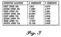
- FIGURE 3 One particular embodiment of the relative locations of the upper and lower connections on such a prior art engine mount is described in the table of FIGURE 3.
- the values in FIGURE 3 are for use with a C.F.M.I.56-7 underwing aft engine mount, as used on (but not limited to) a Boeing 737 Next Generation aircraft (-600/-700/-800).
- a Boeing 737 Next Generation aircraft -600/-700/-800.
- the x and y coordinate system is shown in FIGURE 2 centered at the first lower connection location 75a.
- the locations listed in FIGURE 3 will vary depending on the particular engine application to which a mount is being applied.
- FIGURE 4 is a cross-sectional side view of the second arm 51 of the second link 47 taken along line 4-4 of FIGURE 2.
- the pin-and-clevis joint at the second upper connection location 39b comprises the two previously described clevis tines 42a, 42b within which the second link 47 is held by a clevis pin 43.
- the clevis pin 43 passes through a circular clevis hole 44a located in one of the clevis tines 42a, through a hole 61 in the second link 47, and a circular hole 44b located in the other clevis tine 42b.
- the third lower connection location pin-and-clevis joint is configured similarly.
- Each link hole 61 in the links 45, 47, 53 includes a spherical bearing 63.
- the spherical bearing comprises a bearing ball 65 and a bearing race 67.
- the bearing race 67 is swaged onto the link hole 61 by means of a lip 69.
- the bearing ball 65 is positioned in the bearing race 67 and includes a bearing ball hole 68 through its center.
- the clevis pins 43 pass through the bearing ball holes 68.
- the spherical bearings 63 allow the link to rotate relative to the clevis.
- bushings 91 are located in the pin holes 44a, 44b located in the clevis tines 42a, 42b.
- the bushings 91 extend from the bearing ball 65 to almost the outer surface of the clevis 41.
- the bushings 91 reduce the vibration of the link and clevis pins.
- the clevis tines 42a, 42b; bearing ball 65; bearing race 67; and bushings 91 of all of the clevis assemblies are sized to fit closely together.
- the clevis pins 43 include a head 93 located at one end and threads 95 located at the other end. When inserted in the clevis tines 42a, 42b, the size of the clevis pin 43 is long enough to allow the threaded portion 95 to extend past the clevis tines 42a, 42b. An end cap 97 and nut 99 attached to the threaded end of the clevis pin 43 firmly secure the clevis pin 43 in the clevis 41.
- the diameter of the clevis pin 43 and the diameter of the bearing hole 68 are substantially the same for the clevises 41 at the first, second, and fourth upper connection locations 39a, 39b, 39d and at the first, second, and fourth lower connection locations 75a, 75b, 75d.
- the diameter of the bearing ball hole 68 is slightly larger than the radius of the clevis pin 43.
- the diametric gap between the clevis pin 43 and bearing ball hole 68 of the third lower connection location 75c is approximately 7.87 mm (0.310 inch).
- the diametric gap between the clevis pin 43 and bearing ball hole 68 of the third upper connection location 39c is approximately 5.08 mm (0.200 inch). As discussed in more detail below, the diametric gaps ensure that the links will float around the clevis pin and will not contact the clevis pin during normal operation. Obviously, these dimensions are to be taken as exemplary, since other dimensions may be better for other applications.
- All of the link holes 61 are circular and are formed about an axis normal to the outer surface of each of the links 45, 47, 53.
- the link holes 61 are sized to fit closely against the bearing race 67, which is designed to fit closely about the bearing ball 65.
- the links are positioned within the clevises 41 at a slight tilt. The precise tilt amount will depend upon the amount of movement expected due to thermal expansion at a particular connection location during flight. Even though the links 45, 47, 53 may be tilted at a different angle, during the cruise phase of flight, the movement of the engine 11 will cause all links to become generally vertically oriented and transversely aligned relative to the longitudinal axis 13 of the engine 11.
- FIGURE 5 is a schematic view of the failsafe aft engine mount 19 of FIGURE 2, showing the position of the links 45, 47, 53 during normal operations.
- the links 45, 47, 53 and clevis pins 43 are sized and placed within the aft engine mount 19 so that under normal loading conditions, the first link 45 and the second arm 57 of the third link 53 carry substantially all of the vertical loads, first arm 49 of the second link 47 carries substantially all of the horizontal loads, the second arm 51 of the second link 47 carries no loads, and the first arm 55 of the third link 53 carries no loads.
- the upper and lower connection locations are shown by a dot in the center of each of the circles of FIGURE 5.
- the dots also indicate the general axial center of the clevis pin 43.
- a single circle surrounds the first, second and fourth upper connection locations 39a, 39b, 39d and the first, second, and fourth lower connection locations 75a, 75b, 75d indicating that the clevis pin 43 and bearing ball hole 68 at that connection location are sized to fit one another closely, as described above.
- At the third upper connection location 39c and the third lower connection location 75c there are two circles indicating that the bearing ball hole diameter is larger than the clevis pin radius.
- the large circle represents the bearing ball hole 68 and the smaller circle represents the clevis pin 43 diameter.
- the lines 77 connecting the connection locations of the links 45, 47, 53 are straight and show that the loading between two connection locations follows a straight path through a link. Therefore, no link is subjected to a bending load in a non-failure condition.
- FIGURE 6 is a schematic view of the aft engine mount 19 of FIGURE 2, showing the position of the second and third links 47, 53 during a failed first link 45 condition. If the first link 45 fails, then the bearing ball 65 of the second arm 51 of the second link 47 will be forced into contact with the clevis pin 43 at the clevis joint of the third lower connection location 75c (as shown in FIGURE 6). This allows the second link 47 to work with the remaining third link 53 to absorb the loads previously carried by the failed first link 45. The clevis pin 43 of the clevis joint at the third upper connection location 39c moves closer to the bearing ball hole 68 in the first arm 55 of the third link 53 (as shown in FIGURE 6). However, a connection is not made.
- FIGURE 7 is a schematic view of the aft engine mount 19 of FIGURE 2, showing the position of the first and third links 45, 53 during a failed second link 47 condition. If the second link 47 fails, then the bearing ball 65 of the first arm 55 of the third link 53 will be forced into contact with the clevis pin 43 at the clevis joint of the third upper connection location 39c. The third link 53 works with the first link 45 to absorb the loads previously carried by the failed second link 47.
- FIGURE 8 is a schematic view of the aft engine mount 19 of FIGURE 2, showing the position of the first and second links 45, 47 during a failed third link 53 condition. If the third link 53 fails, then the bearing ball 65 of the second arm 51 of the second link 47 will be forced into contact with the clevis pin 43 at the clevis joint of the third lower connection location 75c. This allows the second link 47 to work with the remaining first link 45 to absorb the loads previously carried by the failed third link 53.
- FIGURES 9-13 illustrate a failsafe aft engine mount formed in accordance with the present invention.
- This novel engine mount is similar to the mount described with reference to FIGURES 2-8, with the exception of changes to the third link 53, its connection to the upper fitting, and the manner in which the mount operates during failure conditions.
- the novel third link 153 also has a dog leg shape formed by a peg 155 and a substantially straight arm 157.
- the peg 155 and arm 157 define an angle of roughly 115 degrees.
- the peg 155 extends inwardly (i.e., toward the mount middle portion) from an upper region of the third link 153.
- the upper fitting 31 includes a hole 159 within which the peg 155 is inserted.
- the hole is formed through the structural webbing of the upper fitting.
- Both the peg and the hole are cross-sectionally circular or ovoid, with the hole cross-sectional shape being larger than the peg cross-sectional shape.
- the peg does not contact the hole surfaces.
- the peg is spaced in the range of about 2.54 mm to 7.62 mm (0.100 inches to 0.300 inches) from its side surfaces to the upper fitting hole surfaces during normal operations. The preferred distance being about 6.4 mm (1 ⁇ 4 inch) between the peg side surfaces and the upper fitting hole surfaces during normal operations.
- FIGURE 10 is a schematic view of the novel failsafe aft engine mount of FIGURE 9, showing the position of the links 45, 47, 53 during normal operations.
- the first link 45 and the third link arm 157 carry substantially all of the vertical loads
- the first arm 49 of the second link 47 carries substantially all of the horizontal loads
- the second arm of the second link 47 carries no loads
- the peg 155 of the third link carries no loads.
- FIGURES 11-13 Operation of the mount during a failed link condition is shown schematically in FIGURES 11-13.
- the upper and lower connection locations are shown by a dot or cross in the center of each of the circles.
- the dots also indicate the general axial center of the clevis pin 43.
- FIGURE 11 is a schematic view of the aft engine mount of FIGURE 9, showing the position of the second and third links 47, 153 during a failed first link 45 condition. If the first link 45 fails, then the bearing ball of the second arm 51 of the second link 47 will be forced into contact with the clevis pin 43 at the clevis joint of the third lower connection location 75c. This allows the second link 47 to work with the remaining third link 153 to absorb the loads previously carried by the failed first link 45.
- the third link peg 155 moves closer to the upper fitting hole 159 surfaces as shown in FIGURE 11, however, a connection is not made between the peg 155 and the hole 159 at this time.
- FIGURE 12 is a schematic view of the aft engine mount of FIGURE 9, showing the position of the first and third links 45, 53 during a failed second link 47 condition. If the second link fails, then the third link peg 155 is forced into contact with the upper fitting hole 159. Because the peg is acting as an anti-rotation member, the peg (and the hole) may be oriented from the other third link portions (and the upper fitting) in any one of a number of directions. What is important to the present invention is that the peg and hole are configured to limit the movement of the third link during a second link failure condition. The third link 153 thus works with the first link 45 to absorb the loads previously carried by the now failed second link 47.
- FIGURE 13 is a schematic view of the aft engine mount of FIGURE 9, showing the position of the first and second links 45, 47 during a failed third link 153 condition.
- the bearing ball 65 of the second arm 51 of the second link 47 is forced into contact with the clevis pin 43 at the clevis joint of the third lower connection location 75c.
Landscapes
- Engineering & Computer Science (AREA)
- Aviation & Aerospace Engineering (AREA)
- Chemical & Material Sciences (AREA)
- Combustion & Propulsion (AREA)
- Mechanical Engineering (AREA)
- General Engineering & Computer Science (AREA)
- Vibration Prevention Devices (AREA)
- Springs (AREA)
- Body Structure For Vehicles (AREA)
Claims (10)
- Ausfallsichere Triebwerkshalterung (19) zum Anbringen eines Triebswerksgehäuses (71) eines Strahltriebwerks (11) an einer Trägerstruktur (17) auf bzw. an einem Flugzeug, umfassend:eine an der Flugzeugträgerstruktur (17) anbringbare obere Armatur (31), wobei die obere Armatur (31) einen unteren Rand aufweist, der einen ersten, zweiten und dritten oberen Verbindungsort (39a, 39b, 39d) hat, welche in einer Ebene lokalisiert sind, die generell quer zu der Längsmittellinie des Triebwerks (11) verläuft;einen Bügel- bzw. Gabelkopfstreifen (73), der an dem äußeren Umfang des Triebwerksgehäuses (71) in einer Ebene angebracht ist, die generell quer zu der Längsmittellinie des Triebwerks (11) verläuft, wobei der Bügel- bzw. Gabelkopfstreifen (73) einen ersten, zweiten, dritten und vierten unteren Verbindungsort (75a, 75b, 75c, 75d) umfasst, die in einer Ebene lokalisiert sind, welche generell quer zu der Längsmittellinie des Triebwerks (11) verläuft;ein im wesentlichen gerades erstes Verbindungsglied (45), das eine Verbindung zu der oberen Armatur (31) an dem ersten oberen Verbindungsort (39a) bildet und eine Verbindung zu dem Bügel- bzw. Gabelkopfstreifen (73) an dem ersten unteren Verbindungsort (75a) bildet;ein zweites Verbindungsglied (47), das einen ersten Arm (49) und einen zweiten Arm (51) enthält, wobei der erste Arm (49) eine Verbindung zu dem Bügel- bzw. Gabelkopfstreifen (73) an dem zweiten unteren Verbindungsort (75b) bildet und eine Verbindung mit der oberen Armatur (31) an dem zweiten oberen Verbindungsort (39b) bildet, wobei der zweite Arm (51) eine Verbindung zu dem Bügel- bzw. Gabelkopfstreifen (73) an dem dritten unteren Verbindungsort (75c) bildet; undein drittes Verbindungsglied (153), das eine Verbindung zu der oberen Armatur (31) an dem dritten oberen Verbindungsort (39d) bildet und eine Verbindung zu dem Bügel- bzw. Gabelkopfstreifen (73) an dem vierten unteren Verbindungsort (75d) bildet, dadurch gekennzeichnet, dass das dritte Verbindungsglied (153) eine Nase (155) umfasst, die sich von einem oberen Bereich des dritten Verbindungsglieds (153) aus erstreckt, wobei die Nase (155) in ein Loch (159) einfügbar ist, das in der oberen Armatur (31) ausgebildet ist.
- Ausfallsichere Triebwerkshalterung (19) gemäß Anspruch 1, dadurch gekennzeichnet, dass die Verbindungen der Verbindungsglieder (45, 47, 153) zu den oberen Verbindungsorten (39a, 39b, 39d) der oberen Armatur und zu den unteren Verbindungsorten (75a-d) des Bügel- bzw. Gabelkopfstreifens (73) Bolzen-und-Bügel-Verbindungen bzw. Bolzen-und-Gabelkopf-Verbindungen (41-44) sind.
- Ausfallsichere Triebwerkshalterung (19) gemäß Anspruch 2, gekennzeichnet durch sphärische Lager (65, 67) an bzw. in den Bolzen-und-Bügel-Verbindungen bzw. Bolzen-und-Gabelkopf-Verbindungen (41-44), die so positioniert sind, dass alle Verbindungsglieder (45, 47, 153) in generell der gleichen Querebene relativ zu der Längsmittellinie des Triebwerks (11) während des normalen Reiseflugbetriebs des Flugs liegen.
- Ausfallsichere Triebwerkshalterung (19) gemäß irgendeinem der vorhergehenden Ansprüche, dadurch gekennzeichnet, dass die obere Armatur (31) weiter strukturell verstärkte bzw. bewehrte Teile bzw. Bereiche (35) umfasst.
- Ausfallsichere Triebwerkshalterung (19) gemäß irgendeinem der vorhergehenden Ansprüche, dadurch gekennzeichnet, dass die obere Armatur (31) weiter eine Anbringungsplattform (33) umfasst, die für die Verbindung mit der Flugzeugträgerstruktur (17) geeignet ist.
- Ausfallsichere Triebwerkshalterung (19) gemäß irgendeinem der vorhergehenden Ansprüche, dadurch gekennzeichnet, dass der zweite Arm (51) des zweiten Verbindungsglieds (47) so angeordnet bzw. eingerichtet ist, dass er während des normalen Flugzeugbetriebs unbelastet ist und/oder so angeordnet bzw. eingerichtet ist, dass er mit dem ersten Verbindungsglied (45) zum Tragen der Triebwerkslasten bzw. -belastungen zusammenarbeitet, sollte das dritte Verbindungsglied (153) ausfallen.
- Ausfallsichere Triebwerkshalterung gemäß irgendeinem der vorhergehenden Ansprüche, dadurch gekennzeichnet, dass die Nase (155) des dritten Verbindungsglieds (153) so positioniert ist, dass sie während des normalen Flugzeugbetriebs unbelastet ist und/oder so positioniert ist, dass sie während eines Ausfalls des ersten Verbindungsglieds (145) unbelastet ist.
- Ausfallsichere Triebwerkshalterung (19) gemäß irgendeinem der vorhergehenden Ansprüche, dadurch gekennzeichnet, dass die Nase (155) des dritten Verbindungsglieds (153) und das Loch (159) der oberen Armatur so angeordnet sind, dass sie mit dem ersten Verbindungsglied (45) zu Tragen der Triebwerksbelastungen bzw. -lasten zusammenarbeiten, sollte das zweite Verbindungsglied (47) ausfallen.
- Ausfallsichere Triebwerkshalterung (19) gemäß irgendeinem der vorhergehenden Ansprüche, dadurch gekennzeichnet, dass die Nase (155) des dritten Verbindungsglieds (153) querschnittsmäßig von eiförmiger Gestalt ist.
- Ausfallsichere Triebwerkshalterung gemäß Anspruch 9, dadurch gekennzeichnet, dass die Nase (155) in dem Bereich von etwa 2,54 mm bis 7,62 mm (0,100 Zoll bis 0,300 Zoll) um ihre Seitenoberflächen von den Oberflächen der Oberflächen des Lochs (159) der oberen Armatur während normalen Operationen bzw. Betriebsweisen beabstandet ist, und vorzugsweise etwa 6,4 mm (1/4 Zoll) an ihren Seitenoberflächen von den Oberflächen des Lochs der oberen Armatur (159) während normalen Operationen bzw. Betriebsweisen beabstandet ist.
Applications Claiming Priority (2)
| Application Number | Priority Date | Filing Date | Title |
|---|---|---|---|
| US08/834,329 US5860623A (en) | 1995-05-03 | 1997-04-14 | Three link failsafe engine mount |
| US834329 | 1997-04-14 |
Publications (3)
| Publication Number | Publication Date |
|---|---|
| EP0872418A2 EP0872418A2 (de) | 1998-10-21 |
| EP0872418A3 EP0872418A3 (de) | 1999-01-07 |
| EP0872418B1 true EP0872418B1 (de) | 2002-02-27 |
Family
ID=25266675
Family Applications (1)
| Application Number | Title | Priority Date | Filing Date |
|---|---|---|---|
| EP98201087A Expired - Lifetime EP0872418B1 (de) | 1997-04-14 | 1998-04-07 | Ausfallsichere Triebwerksaufhängung durch drei Gestänge mit drei Hebeln |
Country Status (4)
| Country | Link |
|---|---|
| US (1) | US5860623A (de) |
| EP (1) | EP0872418B1 (de) |
| CN (1) | CN1082004C (de) |
| DE (1) | DE69803951T2 (de) |
Cited By (1)
| Publication number | Priority date | Publication date | Assignee | Title |
|---|---|---|---|---|
| RU2487821C2 (ru) * | 2007-12-07 | 2013-07-20 | Снекма | Узел подвески турбореактивного двигателя к летательному аппарату |
Families Citing this family (62)
| Publication number | Priority date | Publication date | Assignee | Title |
|---|---|---|---|---|
| US5927644A (en) * | 1997-10-08 | 1999-07-27 | General Electric Company | Double failsafe engine mount |
| US5921500A (en) * | 1997-10-08 | 1999-07-13 | General Electric Company | Integrated failsafe engine mount |
| FR2774358B1 (fr) * | 1998-02-04 | 2000-04-21 | Aerospatiale | Dispositif d'accrochage d'un moteur d'aeronef |
| FR2775465B1 (fr) * | 1998-03-02 | 2000-05-26 | Aerospatiale | Dispositif d'accrochage d'un moteur sur un pylone d'aeronef |
| FR2799432A1 (fr) * | 1999-10-07 | 2001-04-13 | Snecma | Suspension a securite integree pour groupes motopropulseurs d'aeronefs |
| US6330995B1 (en) * | 2000-02-29 | 2001-12-18 | General Electric Company | Aircraft engine mount |
| FR2806699B1 (fr) * | 2000-03-22 | 2002-05-10 | Aerospatiale Matra Airbus | Dispositif de reprise de poussee apte a relier un turbomoteur et un mat d'aeronef |
| CA2413958A1 (en) | 2000-06-02 | 2001-12-13 | Lord Corporation | Vibration isolator |
| US6715746B2 (en) | 2000-07-21 | 2004-04-06 | Lord Corporation | Vibration isolation device with load dependent stiffness |
| US6517027B1 (en) * | 2001-12-03 | 2003-02-11 | Pratt & Whitney Canada Corp. | Flexible/fixed support for engine cowl |
| US6607165B1 (en) * | 2002-06-28 | 2003-08-19 | General Electric Company | Aircraft engine mount with single thrust link |
| FR2855494B1 (fr) * | 2003-05-27 | 2006-09-22 | Snecma Moteurs | Dispositif d'accrocharge arriere de moteur d'avion |
| FR2855495B1 (fr) * | 2003-05-27 | 2006-11-24 | Snecma Moteurs | Dispositif d'accrochage avant de moteur d'avion |
| US6843449B1 (en) * | 2004-02-09 | 2005-01-18 | General Electric Company | Fail-safe aircraft engine mounting system |
| FR2867155B1 (fr) * | 2004-03-08 | 2007-06-29 | Snecma Moteurs | Suspension d'un moteur a la structure d'un avion |
| FR2868041B1 (fr) * | 2004-03-25 | 2006-05-26 | Snecma Moteurs Sa | Suspension d'un moteur d'avion |
| FR2869874B1 (fr) * | 2004-05-04 | 2006-06-23 | Snecma Moteurs Sa | Moteur d'avion avec des moyens de suspension a la structure d'un avion |
| FR2883839B1 (fr) * | 2005-03-29 | 2007-06-29 | Snecma Moteurs Sa | Suspension arriere de turboreacteur |
| GB0507721D0 (en) | 2005-04-16 | 2005-05-25 | Rolls Royce Plc | Gas turbine engine mounting arrangement |
| US20070056292A1 (en) * | 2005-09-14 | 2007-03-15 | Honeywell International, Inc. | Auxiliary power unit case flange to cone bolt adapter |
| FR2905932B1 (fr) | 2006-09-20 | 2008-12-05 | Airbus France Sa | Agencement pour attache de dispositif d'accrochage d'un moteur d'aeronef |
| US7810239B2 (en) | 2006-10-23 | 2010-10-12 | United Technologies Corporation | Engine mount bearing sleeve repair |
| FR2917711B1 (fr) * | 2007-06-25 | 2010-01-15 | Snecma | Suspension d'un turbomoteur a la structure d'un aeronef |
| FR2921900B1 (fr) * | 2007-10-05 | 2011-03-18 | Aircelle Sa | Ensemble propulsif pour aeronef. |
| US8167237B2 (en) | 2008-03-21 | 2012-05-01 | United Technologies Corporation | Mounting system for a gas turbine engine |
| DE102008021431A1 (de) * | 2008-04-29 | 2009-11-12 | Airbus Deutschland Gmbh | Flugzeug mit einer Energie-Versorgungsvorrichtung |
| FR2931800B1 (fr) * | 2008-05-29 | 2010-07-30 | Airbus France | Dispositif de reprise des efforts de poussee pour mat d'accrochage de moteur d'aeronef, comprenant des bielles laterales a butees de palonnier integrees |
| US20140174056A1 (en) * | 2008-06-02 | 2014-06-26 | United Technologies Corporation | Gas turbine engine with low stage count low pressure turbine |
| FR2939100B1 (fr) * | 2008-12-01 | 2010-12-31 | Airbus France | Ensemble moteur pour aeronef comprenant une structure rigide modulaire de mat d'accrochage |
| FR2939409B1 (fr) * | 2008-12-08 | 2011-02-11 | Airbus France | Systeme de fixation entre deux composants tels qu'un moteur d'aeronef et son mat d'accrochage |
| US8342444B2 (en) * | 2008-12-16 | 2013-01-01 | The Boeing Company | Fail safe extended torque box strut-to-wing mount |
| US20100189502A1 (en) * | 2009-01-22 | 2010-07-29 | Basta Samuel T | Watercraft lift system |
| US8313293B2 (en) * | 2009-05-15 | 2012-11-20 | Pratt & Whitney Canada Corp. | Turbofan mounting system |
| US8567202B2 (en) | 2009-05-15 | 2013-10-29 | Pratt & Whitney Canada Corp. | Support links with lockable adjustment feature |
| US8979491B2 (en) | 2009-05-15 | 2015-03-17 | Pratt & Whitney Canada Corp. | Turbofan mounting arrangement |
| FR2948635B1 (fr) * | 2009-07-31 | 2011-08-26 | Airbus Operations Sas | Assemblage pour aeronef comprenant un mat d'accrochage de turbomachine dont les moyens d'attache sur la voilure sont agences en t |
| KR101767071B1 (ko) | 2010-06-14 | 2017-08-10 | 로오드 코포레이션 | 헬리콥터 엔진 장착 시스템 및 방법 |
| FR2965796B1 (fr) * | 2010-10-07 | 2013-06-07 | Snecma | Suspension d'un moteur a un mat d'aeronef comportant un arceau de suspension |
| FR2973339B1 (fr) * | 2011-03-29 | 2014-08-22 | Snecma | Dispositif de suspension d'une turbomachine a un avion |
| US20130074517A1 (en) * | 2011-09-23 | 2013-03-28 | United Technologies Corporation | Gas turbine engine mount assembly |
| GB201118548D0 (en) * | 2011-10-27 | 2011-12-07 | Airbus Operations Ltd | Plain journal bearing |
| FR2982331B1 (fr) * | 2011-11-07 | 2013-11-29 | Eurocopter France | Mecanisme d'articulation en rotule entre une chape et une bielle, notamment pour un appareillage de commande equipant un giravion |
| US9297438B2 (en) * | 2012-01-25 | 2016-03-29 | Honeywell International Inc. | Three parameter damper anisotropic vibration isolation mounting assembly |
| US9365278B2 (en) * | 2013-01-21 | 2016-06-14 | The Boeing Company | Variation compensating assembly |
| US9863324B2 (en) * | 2013-03-21 | 2018-01-09 | United Technologies Corporation | Oil tank mount with stiffeners |
| GB201315968D0 (en) * | 2013-09-09 | 2013-10-23 | Rolls Royce Plc | Aircraft engine mount |
| US10059412B1 (en) | 2014-04-11 | 2018-08-28 | Basta Inc. | Boat lift systems and methods |
| US9784129B2 (en) | 2014-08-01 | 2017-10-10 | Pratt & Whitney Canada Corp. | Rear mount assembly for gas turbine engine |
| WO2016112187A2 (en) * | 2015-01-07 | 2016-07-14 | Lord Corporation | Aircraft engine mount |
| US10066552B2 (en) * | 2016-03-14 | 2018-09-04 | Hamilton Sundstrand Corporation | One degree-of-constraint semi-fusible gearbox mounting link |
| US10006373B2 (en) * | 2016-03-14 | 2018-06-26 | Hamilton Sundstrand Coporation | Two degree-of-constraint semi-fusible gearbox mounting link |
| FR3058986B1 (fr) * | 2016-11-21 | 2021-04-16 | Airbus Operations Sas | Attache arriere d'un moteur d'aeronef comportant des temoins de rupture |
| US10858083B1 (en) | 2017-01-22 | 2020-12-08 | Basta Ip Inc. | Bunk mounting systems and methods for watercraft lifts |
| FR3062439B1 (fr) * | 2017-02-02 | 2019-03-15 | Safran Transmission Systems | Chape de turbomachine a filtre integre et son procede de realisation |
| FR3081836B1 (fr) * | 2018-06-01 | 2020-11-06 | Airbus Operations Sas | Ensemble propulsif d'aeronef et procede de verification de l'integrite d'une attache moteur de l'ensemble propulsif |
| FR3093546B1 (fr) * | 2019-03-05 | 2021-04-23 | Airbus Operations Sas | Liaison de sécurité d’une attache moteur d’un ensemble propulsif aéronef et ensemble propulsif d’aéronef équipé d’une telle liaison de sécurité |
| FR3093704B1 (fr) * | 2019-03-11 | 2021-06-11 | Airbus Operations Sas | Attache moteur arrière d’un ensemble propulsif d’aéronef |
| US11820510B2 (en) * | 2019-03-26 | 2023-11-21 | Yaborã Industria Aeronautica S.A. | Quickly adjustable fail-safe link bar assemblies especially useful for connecting structural components of an aircraft |
| US20210023927A1 (en) * | 2019-07-24 | 2021-01-28 | Honeywell International Inc. | System and method for gas turbine engine mount with seal |
| US11479104B2 (en) * | 2019-07-24 | 2022-10-25 | Honeywell International Inc. | System and method for gas turbine engine mount with seal |
| CN110745250B (zh) * | 2019-11-22 | 2023-04-18 | 中国航发沈阳黎明航空发动机有限责任公司 | 一种航空发动机点火附件装配式安装结构及安装方法 |
| FR3124164A1 (fr) * | 2021-06-30 | 2022-12-23 | Airbus Operations | Manille de fixation d’un moteur d’aeronef comprenant un couple de revetements antifriction encapsules, et aeronef comprenant une telle manille. |
Family Cites Families (19)
| Publication number | Priority date | Publication date | Assignee | Title |
|---|---|---|---|---|
| US3844115A (en) * | 1973-02-14 | 1974-10-29 | Gen Electric | Load distributing thrust mount |
| US4055041A (en) * | 1974-11-08 | 1977-10-25 | The United States Of America As Represented By The Administrator Of The National Aeronautics And Space Administration | Integrated gas turbine engine-nacelle |
| GB1521847A (en) * | 1976-04-30 | 1978-08-16 | Rolls Royce | Attachment for attaching jet propulsion engines to vehicle structure |
| WO1985002596A1 (en) * | 1983-12-08 | 1985-06-20 | The Boeing Company | Aft engine mount |
| US4603821A (en) * | 1983-12-30 | 1986-08-05 | The Boeing Company | System for mounting a jet engine |
| US4717094A (en) * | 1986-05-19 | 1988-01-05 | The Boeing Company | Aircraft engine mount system with vibration isolators |
| FR2599708A1 (fr) * | 1986-06-10 | 1987-12-11 | Snecma | Dispositif d'accrochage arriere de securite d'un turboreacteur sur un mat d'avion |
| GB2224707B (en) * | 1988-11-12 | 1992-06-10 | Rolls Royce Plc | Improvements in or relating to engine mounting integrity |
| EP0431800B1 (de) * | 1989-12-05 | 1994-08-31 | ROLLS-ROYCE plc | Ausfallsichere Haltevorrichtung für Treibwerke |
| FR2680353B1 (fr) * | 1991-08-14 | 1993-10-15 | Snecma | Structure d'accrochage arriere d'un turboreacteur. |
| US5174525A (en) * | 1991-09-26 | 1992-12-29 | General Electric Company | Structure for eliminating lift load bending in engine core of turbofan |
| GB9125011D0 (en) * | 1991-11-25 | 1992-01-22 | Rolls Royce Plc | A mounting arrangement for a gas turbine engine |
| US5275357A (en) * | 1992-01-16 | 1994-01-04 | General Electric Company | Aircraft engine mount |
| US5320307A (en) * | 1992-03-25 | 1994-06-14 | General Electric Company | Aircraft engine thrust mount |
| US5351930A (en) * | 1992-08-11 | 1994-10-04 | Lord Corporation | Mounting for engines and the like |
| US5277382A (en) * | 1992-10-13 | 1994-01-11 | General Electric Company | Aircraft engine forward mount |
| US5303880A (en) * | 1992-10-28 | 1994-04-19 | General Electric Company | Aircraft engine pin mount |
| US5649417A (en) * | 1995-03-24 | 1997-07-22 | The Boeing Company | Fail-safe engine mount system |
| US5620154A (en) * | 1995-05-03 | 1997-04-15 | The Boeing Company | Three link failsafe engine mount |
-
1997
- 1997-04-14 US US08/834,329 patent/US5860623A/en not_active Expired - Lifetime
-
1998
- 1998-04-07 DE DE69803951T patent/DE69803951T2/de not_active Expired - Lifetime
- 1998-04-07 EP EP98201087A patent/EP0872418B1/de not_active Expired - Lifetime
- 1998-04-10 CN CN98106291A patent/CN1082004C/zh not_active Expired - Lifetime
Cited By (1)
| Publication number | Priority date | Publication date | Assignee | Title |
|---|---|---|---|---|
| RU2487821C2 (ru) * | 2007-12-07 | 2013-07-20 | Снекма | Узел подвески турбореактивного двигателя к летательному аппарату |
Also Published As
| Publication number | Publication date |
|---|---|
| US5860623A (en) | 1999-01-19 |
| EP0872418A3 (de) | 1999-01-07 |
| CN1082004C (zh) | 2002-04-03 |
| EP0872418A2 (de) | 1998-10-21 |
| CN1196318A (zh) | 1998-10-21 |
| DE69803951T2 (de) | 2002-11-28 |
| DE69803951D1 (de) | 2002-04-04 |
Similar Documents
| Publication | Publication Date | Title |
|---|---|---|
| EP0872418B1 (de) | Ausfallsichere Triebwerksaufhängung durch drei Gestänge mit drei Hebeln | |
| US5620154A (en) | Three link failsafe engine mount | |
| US5649417A (en) | Fail-safe engine mount system | |
| US5725181A (en) | Aircraft engine thrust mount | |
| EP1561684B1 (de) | Ausfallsichere Flugtriebwerksaufhängung | |
| US7566029B2 (en) | Suspension for suspending a jet engine on an aircraft strut | |
| EP0164352B1 (de) | Triebwerkshinteraufhängung | |
| EP0311155B1 (de) | Schwingungsdämpfungsbefestigung eines Triebwerks | |
| RU2435968C2 (ru) | Задний узел подвески двигателя летательного аппарата со сдвоенной серьгой и силовая установка, содержащая такой узел | |
| US5871176A (en) | Redundant front suspension system for a turboshaft engine | |
| US5871177A (en) | Redundant front suspension system for a turboshaft engine | |
| US5275357A (en) | Aircraft engine mount | |
| US5873547A (en) | Aircraft engine thrust mount | |
| US5921500A (en) | Integrated failsafe engine mount | |
| US5871175A (en) | Redundant front suspension system for a turboshaft engine | |
| US4875655A (en) | Vibration isolating engine mount | |
| US4392622A (en) | Combined beam support for landing gear | |
| US11338929B2 (en) | Forward engine attachment system for an aircraft engine comprising a direct coupling between the jet engine pylon and the engine | |
| US5028001A (en) | Method of vibration isolating an aircraft engine | |
| US5642615A (en) | Turbofan engine with a floating pod | |
| US11572184B2 (en) | Front engine attachment system for an aircraft engine, having rod systems with two rods | |
| US20110174918A1 (en) | Device for fastening a turboprop, preferably under an aircraft wing | |
| US6413048B1 (en) | Elastomeric bearing | |
| US20210010424A1 (en) | Fail-safe engine support system | |
| CN1174799A (zh) | 三链节式失效安全引擎安装架 |
Legal Events
| Date | Code | Title | Description |
|---|---|---|---|
| PUAI | Public reference made under article 153(3) epc to a published international application that has entered the european phase |
Free format text: ORIGINAL CODE: 0009012 |
|
| AK | Designated contracting states |
Kind code of ref document: A2 Designated state(s): DE FR GB |
|
| AX | Request for extension of the european patent |
Free format text: AL;LT;LV;MK;RO;SI |
|
| PUAL | Search report despatched |
Free format text: ORIGINAL CODE: 0009013 |
|
| AK | Designated contracting states |
Kind code of ref document: A3 Designated state(s): AT BE CH CY DE DK ES FI FR GB GR IE IT LI LU MC NL PT SE |
|
| AX | Request for extension of the european patent |
Free format text: AL;LT;LV;MK;RO;SI |
|
| 17P | Request for examination filed |
Effective date: 19990707 |
|
| AKX | Designation fees paid |
Free format text: DE FR GB |
|
| 17Q | First examination report despatched |
Effective date: 20000720 |
|
| GRAG | Despatch of communication of intention to grant |
Free format text: ORIGINAL CODE: EPIDOS AGRA |
|
| GRAG | Despatch of communication of intention to grant |
Free format text: ORIGINAL CODE: EPIDOS AGRA |
|
| GRAH | Despatch of communication of intention to grant a patent |
Free format text: ORIGINAL CODE: EPIDOS IGRA |
|
| GRAH | Despatch of communication of intention to grant a patent |
Free format text: ORIGINAL CODE: EPIDOS IGRA |
|
| REG | Reference to a national code |
Ref country code: GB Ref legal event code: IF02 |
|
| GRAA | (expected) grant |
Free format text: ORIGINAL CODE: 0009210 |
|
| AK | Designated contracting states |
Kind code of ref document: B1 Designated state(s): DE FR GB |
|
| REF | Corresponds to: |
Ref document number: 69803951 Country of ref document: DE Date of ref document: 20020404 |
|
| ET | Fr: translation filed | ||
| PLBE | No opposition filed within time limit |
Free format text: ORIGINAL CODE: 0009261 |
|
| STAA | Information on the status of an ep patent application or granted ep patent |
Free format text: STATUS: NO OPPOSITION FILED WITHIN TIME LIMIT |
|
| 26N | No opposition filed |
Effective date: 20021128 |
|
| REG | Reference to a national code |
Ref country code: FR Ref legal event code: PLFP Year of fee payment: 19 |
|
| REG | Reference to a national code |
Ref country code: FR Ref legal event code: PLFP Year of fee payment: 20 |
|
| PGFP | Annual fee paid to national office [announced via postgrant information from national office to epo] |
Ref country code: FR Payment date: 20170426 Year of fee payment: 20 Ref country code: DE Payment date: 20170427 Year of fee payment: 20 Ref country code: GB Payment date: 20170427 Year of fee payment: 20 |
|
| REG | Reference to a national code |
Ref country code: DE Ref legal event code: R071 Ref document number: 69803951 Country of ref document: DE |
|
| REG | Reference to a national code |
Ref country code: GB Ref legal event code: PE20 Expiry date: 20180406 |
|
| PG25 | Lapsed in a contracting state [announced via postgrant information from national office to epo] |
Ref country code: GB Free format text: LAPSE BECAUSE OF EXPIRATION OF PROTECTION Effective date: 20180406 |