EP0871964B1 - Paired electrical cable having improved transmission properties and method for making same - Google Patents
Paired electrical cable having improved transmission properties and method for making same Download PDFInfo
- Publication number
- EP0871964B1 EP0871964B1 EP97901317A EP97901317A EP0871964B1 EP 0871964 B1 EP0871964 B1 EP 0871964B1 EP 97901317 A EP97901317 A EP 97901317A EP 97901317 A EP97901317 A EP 97901317A EP 0871964 B1 EP0871964 B1 EP 0871964B1
- Authority
- EP
- European Patent Office
- Prior art keywords
- cable
- twist
- twisted
- pair
- paired
- Prior art date
- Legal status (The legal status is an assumption and is not a legal conclusion. Google has not performed a legal analysis and makes no representation as to the accuracy of the status listed.)
- Expired - Lifetime
Links
- 238000000034 method Methods 0.000 title description 58
- 230000005540 biological transmission Effects 0.000 title description 9
- 239000004020 conductor Substances 0.000 claims description 47
- 239000012777 electrically insulating material Substances 0.000 claims description 2
- 230000010355 oscillation Effects 0.000 claims description 2
- 150000001875 compounds Chemical class 0.000 description 28
- 230000008569 process Effects 0.000 description 28
- 238000001125 extrusion Methods 0.000 description 20
- 238000009413 insulation Methods 0.000 description 14
- 238000004519 manufacturing process Methods 0.000 description 8
- 238000010791 quenching Methods 0.000 description 7
- 230000000171 quenching effect Effects 0.000 description 7
- 230000001351 cycling effect Effects 0.000 description 6
- 230000000694 effects Effects 0.000 description 6
- 239000000463 material Substances 0.000 description 6
- 238000010276 construction Methods 0.000 description 5
- 230000008901 benefit Effects 0.000 description 4
- 238000002474 experimental method Methods 0.000 description 4
- 230000009467 reduction Effects 0.000 description 4
- 230000004044 response Effects 0.000 description 4
- 238000000576 coating method Methods 0.000 description 3
- 238000003780 insertion Methods 0.000 description 3
- 230000037431 insertion Effects 0.000 description 3
- 239000011810 insulating material Substances 0.000 description 3
- 230000000737 periodic effect Effects 0.000 description 3
- 229920003023 plastic Polymers 0.000 description 3
- 239000004033 plastic Substances 0.000 description 3
- XLYOFNOQVPJJNP-UHFFFAOYSA-N water Substances O XLYOFNOQVPJJNP-UHFFFAOYSA-N 0.000 description 3
- 230000009471 action Effects 0.000 description 2
- 230000004075 alteration Effects 0.000 description 2
- 238000013459 approach Methods 0.000 description 2
- 230000009286 beneficial effect Effects 0.000 description 2
- 230000015556 catabolic process Effects 0.000 description 2
- 239000011248 coating agent Substances 0.000 description 2
- 238000007796 conventional method Methods 0.000 description 2
- 238000006731 degradation reaction Methods 0.000 description 2
- 239000003989 dielectric material Substances 0.000 description 2
- 230000006872 improvement Effects 0.000 description 2
- 238000009434 installation Methods 0.000 description 2
- 238000000926 separation method Methods 0.000 description 2
- RYGMFSIKBFXOCR-UHFFFAOYSA-N Copper Chemical compound [Cu] RYGMFSIKBFXOCR-UHFFFAOYSA-N 0.000 description 1
- 239000004698 Polyethylene Substances 0.000 description 1
- 230000004888 barrier function Effects 0.000 description 1
- 230000008859 change Effects 0.000 description 1
- 229910052802 copper Inorganic materials 0.000 description 1
- 239000010949 copper Substances 0.000 description 1
- 230000008878 coupling Effects 0.000 description 1
- 238000010168 coupling process Methods 0.000 description 1
- 238000005859 coupling reaction Methods 0.000 description 1
- 238000013461 design Methods 0.000 description 1
- 230000001627 detrimental effect Effects 0.000 description 1
- 238000005429 filling process Methods 0.000 description 1
- 239000012467 final product Substances 0.000 description 1
- 238000005304 joining Methods 0.000 description 1
- 238000012423 maintenance Methods 0.000 description 1
- 230000010358 mechanical oscillation Effects 0.000 description 1
- 230000007246 mechanism Effects 0.000 description 1
- 238000012986 modification Methods 0.000 description 1
- 230000004048 modification Effects 0.000 description 1
- -1 polyethylene Polymers 0.000 description 1
- 229920000573 polyethylene Polymers 0.000 description 1
- 229920000915 polyvinyl chloride Polymers 0.000 description 1
- 239000004800 polyvinyl chloride Substances 0.000 description 1
- 230000008054 signal transmission Effects 0.000 description 1
- 125000006850 spacer group Chemical group 0.000 description 1
Images




Classifications
-
- H—ELECTRICITY
- H01—ELECTRIC ELEMENTS
- H01B—CABLES; CONDUCTORS; INSULATORS; SELECTION OF MATERIALS FOR THEIR CONDUCTIVE, INSULATING OR DIELECTRIC PROPERTIES
- H01B7/00—Insulated conductors or cables characterised by their form
- H01B7/08—Flat or ribbon cables
- H01B7/0876—Flat or ribbon cables comprising twisted pairs
-
- H—ELECTRICITY
- H01—ELECTRIC ELEMENTS
- H01B—CABLES; CONDUCTORS; INSULATORS; SELECTION OF MATERIALS FOR THEIR CONDUCTIVE, INSULATING OR DIELECTRIC PROPERTIES
- H01B11/00—Communication cables or conductors
- H01B11/002—Pair constructions
Definitions
- the present invention relates generally to an individually-twisted electrical cable pair according to the preamble of claim 1 used for transmitting digital and analog data and voice information signals and relates to a multiple-paired electrical cable.
- the resultant cable pairs and electrical cable possesses superior transmission properties, including minimal structural return loss, near-end crosstalk, and insertion loss when compared to conventional non-pre-twisted cable pairs and electrical cables made therefrom.
- One method of transmitting these signals is by using an individually-twisted pair of electrical conductors such as insulated copper wires. These wires are typically coated with a plastic insulating material by an extrusion process. Although these conductors have been in use for quite some time, especially in the telephone industry, asymmetrical imperfections such as ovality of the surrounding insulating material, out-of roundness or eccentricity of the wire cross-section, and lack of perfect centering of the wire within the insulation tend to limit their ability to transmit data without an insignificant amount of error.
- a conventional method for pairing two insulated wires together is by twisting them together with a double twist pairing machine.
- the wires receive two "lay twists," or two complete rotations about a common axis. per revolution of the machine.
- each individual wire is twisted two turns about its own axis per revolution of the machine in the same direction as the pair lay twists. and this is commonly referred to as "back-twist.”
- back-twist is imparted to each wire at a rate of one twist per lay twist.
- this combination of off-center conductors, out of roundness of insulation, etc., and back-twist generally creates periodic changes in the spacing between the conductors along the length of the twisted pair.
- the periodic spacing between conductors changes from minimum to maximum at a very rapid rate of one cycle per each turn of the pair.
- This short distance is usually only a small fraction of the wavelength of the highest frequency transmitted on the wire pairs, thus generally making the impedance variations transparent.
- the advancing signal travelling down the wire pair sees only the average impedance, which possesses minimal variability in comparison to the relatively high variability in impedance experienced with cable pairs that possess the normally imparted back-twist.
- single twist pairing machines which impart no back-twist are slower than conventional double twist machines. It is generally more difficult to control the wire tension in single twist pairing machines as well. These problems can raise production costs to unacceptably high levels.
- US-A-4,182,105 which defines the closest prior art describes an efficient method and apparatus for forming wire pairs consisting of single wires having different insulations or other wire characteristics.
- the apparatus is taught to be able to pretwist the individual wires prior to pairing them.
- the apparatus shown pretwists both wires in the pair. There is no teaching regarding the relative twist lengths or frequencies used.
- US-A-4,100,721 describes a method and apparatus for twisting four wires into a star quad configuration. It is taught that using pretwisted wires in a star quad configuration to compensate for eccentricities in the insulation layer will reduce crosstalk.
- Such cables typically contain several cable pairs of twisted conductors, enclosed by a plastic jacket.
- the most popular method is to rotate several pairs together in a process known as cabling or stranding. Once this "core" has been formed, a plastic jacket is extruded over the formed core.
- a tapered tip is shaped to receive the coupled cable pairs in one end. As the cable pairs move through this tip, the tip constricts, forcing the cable pairs into individual channels that at the end of the tip are configured along with the die for the particular form the final cable will take. For instance, four cable pairs aligned side-by-side through an oval tip and associated die will form a flat cable, while four cable pairs arranged in a circular configuration through a circular tip and round die will form a round cable.
- the tip is partially placed into a die so that a gap forms between the outer surface of the tip and the inner surface of the die. This gap narrows as the die and the tip taper to the desired final cable size and shape.
- heat softened cable jacketing compound feeds under pressure into the gap between the tip and die. extruding the material out of the exit at the tapered end of the die. which is known as the die face.
- the tip extends only partially into the die so that when the jacketing compound extrudes through the gap to meet the cable pairs, the heat softened jacketing compound forms not only the outside shape of the cable, but may encapsulate and isolate each of the individual pairs as well.
- an electrical cable pair according to claim 1 which possesses superior electrical properties, including lower structural return loss, improved near-end crosstalk response, and reduced insertion loss when compared to conventionally paired cables.
- the invention further provides multiple-paired electrical cables according to claims 11 and 14 which comprise a plurality of multiple-paired cables according to the invention.
- one of the insulated wires Before pairing, one of the insulated wires is pre-twisted about its own longitudinal axis such that the relative degree of pre-twist in the two wires is the same.
- the wires When paired together by a conventional double-twist pairing machine, the wires maintain this pre-twist ratio as they are paired and additionally twisted about a common axis.
- the angular position i.e., a particular position with respect to the center of the wire
- the word "point” refers to a cross-sectional representation of a line of contact between the surfaces of the two wires along the length of the pair of wires.
- the conductor-to-conductor spacing must be constant and non-changing throughout the cable's length. This could be achieved by perfectly centering the conductor in the insulation surrounding it. which is virtually impossible due to inherent limitations using conventional manufacturing techniques.
- the other solution would be to insulate the conductors of a pair simultaneously adjoining or bonding both wires of the pair together at or near the extrusion head. Since the off-centering of conductors occurs largely due to tip and die positioning, this process locks the insulated conductors together prior to the off-centered insulated conductors being able to rotate, therefore creating very uniform conductor-to-conductor spacing throughout the length of cable. This solution, however, leads to increased termination time in the field due to the need to separate the bonded insulated conductors.
- each wire With the pre-twisted wire pair, the relative angular positions of each wire do not remain constant as they rotate about their own axis at different rates. Thus, the line of contact between the surfaces of each wire is constantly changing its angular position so that no point on the surface of one wire stays in contact with any other point on the surface of the other wire through any given twist length.
- This construction has the effect of cycling the variations in spacing between centers of the conductors caused by ovality of the surrounding insulating material, out-of roundness or eccentricity of the wire cross-section, and lack of perfect centering of wire within the insulation at a very high rate per unit length of the pre-twisted cable pair.
- the result is a cable pair having a significant reduction in impedance fluctuation and significantly improved transmission properties up to a signal frequency having approximately a 1/8 wavelength equal to or greater than the distance within which these variations are repeated.
- the pre-twisted cable pair may then be assembled with any number of other such cable pairs to form a cable by a continuous-extrusion tubed jacketing process.
- a tapered, threaded tip is inserted so as to be either flush or near-flush with a matching tapered die of greater inner dimensions.
- the gap created by this diameter differential creates an extrusion path through which jacketing compound flows.
- a number of pre-twisted cable pairs are fed through the receiving end of the tip while heated jacketing compound is simultaneously and continuously fed through the extrusion path between the tip and die outer surfaces. As the pre-twisted cable pairs move to the tapered end of the tip, they are guided into individual channels for final alignment.
- the extruding heated jacketing compound meets and encloses the pre-twisted cable pairs beyond the die exit.
- the newly-jacketed cable pairs exit the die, they pass through a quenching trough which solidifies the jacketing compound to form a cable whose cross-sectional structure consists of internal ridges that do not extend entirely across the inner width of the cable jacket. yet which define individual channels for each of the pre-twisted cable pairs.
- Superior electrical properties of the resultant cable are achieved because the unique tip/die configuration yields a well-defined inner jacket surface and prevents the ridges from bonding to one another, thereby allowing an optimal "air dielectric" about each pair to be maintained, along with uniform pair-to-pair separation in an easily removed jacket.
- pre-twisting combinations may be realized by the present invention according to which only one wire may be pre-twisted uniformly or pre-twisted with random amounts while the other is not pre-twisted at all.
- the cable pair may be surrounded by an outer jacket of electrically insulating material, or by an outer electrostatic shield of electrically conducting material.
- the cable may consist of anywhere from a minimum of one to a large number of cable pairs, all of which may be configured in a flat or round overall cable design.
- the pairs may also be assembled in unidirectional, oscillating, or helical paths in which the cabled pairs first rotate clockwise, and then rotate counterclockwise along the axis of the cable in a given mechanical oscillation cycle.
- twist length or "lay length” are used in the conventional sense as referring to the distance in which each of two paired wires makes one complete 360 degree revolution about a common axis.
- - twist frequency is hereinafter used to define the number of twists per a specified length of wire pair. In this sense, a paired wire set with a 101,6 mm (four inch) twist length has a twist frequency of three twists per 304,8 mm (per foot).
- Figures 1A and 1B depict a conventional set of non-pre-twisted insulated wires before and after pairing via the conventional techniques.
- the longitudinal stripes 10 and 20, depicted on the surface of the insulation surrounding each insulated conductor of wires 30 and 40, are placed in the figures for purposes of illustration only so that a wire's individual rotation about its longitudinal axis may be more easily depicted. Because these wires are not pre-twisted, the longitudinal stripes on each wire in Figure 1A remain in approximately the same angular orientation (i.e., in a straight line at one particular angular position with respect to the center of the wire) for a considerable distance (greater than 1/8 wavelength of the highest frequency to be supported).
- the wires are typically "lay twisted" by a 360 degree revolution about a common axis along a predetermined length known as the twist length or the lay length (and depicted by the dimension "LL"), forming a "cable pair.”
- the illustrative example of Figure 1B depicts a single-lay twist section of a cable pair, a 19 mm (3 ⁇ 4 inch) twist length and a corresponding twist frequency of 52.6 twists per meter (16 twists per foot).
- each of the wires 30 and 40 has also rotated 360 degrees about its own respective longitudinal axis over the 19 mm (3 ⁇ 4 inch) twist length such that one "back-twist" is imparted into each wire for each lay twist of the cable pair.
- the practical effect of this back-twist is twofold, and is shown in Figure 1C, which are cross-sectional views of two wires 30 and 40 shown in quarter twist length increments as they rotate about a common axis as well as their individual axis as indicated by the arrows.
- the first effect of the back-twist phenomenon is that the relative orientation between any two points, such as lines 10 and 20 in Figure 1B, or points 12 and 22 in Figure 1C, remains generally constant throughout the entire twist length.
- this relatively constant conductor-to-conductor spacing renders a relatively slow-changing impedance profile segment 73 over one period of twist, (i.e., one twist length or lay length, as shown by dimension LL) as shown in Figure 1C as a portion of the cable's continuous impedance profile designated by the index numeral 72 which extends along a "rotation'' length (i.e., dimension "RL") of Figure 1 C.
- the twist length and the consistency of wire rotation will slowly vary, causing any given point of contact and the conductor-to-conductor spacing between the two wires to slowly vary as well.
- the impedance measured over any given twist length may be higher or lower than that measured over a twist length in a different location.
- impedance profile 72 of Figure 1C This is shown by impedance profile 72 of Figure 1C, where the continuous impedance profile Z 0 (which is the basis for calculating the average, or characteristic impedance) is curve 72 mapped as a function of paired cable length at a frequency of 100 MHz, for which the quarter-wavelength is approximately 0,46 m (18 inches) (since the velocity of propagation is about 60% for these twisted pairs).
- a target input impedance of 100 ⁇ can typically fluctuate by ⁇ 30 ⁇ , as shown in Figure 1D, which depicts the measured input impedance of this cable pair) given a significant length of cable 100 m (328 feet) in which multiple reflections occur and add in phase, as shown in Figure 1D.
- this fluctuation in input impedance is very gradual when experienced over any given 51 mm (two-inch) twist length as seen by the curve segment 73. This slow variation is exacerbated if either wire has poor centering, ovality, or is out of round.
- the impedance profile 72 is relatively constant as measured over one twist length, its average magnitude tends to increase or decrease over longer distances as the effects of the aforementioned imperfections and variations are experienced as indicated by different curve segments 72 and 73.
- This increased fluctuation in impedance over longer distances results in excessive structural return losses (SRL) in electronic signals having frequencies in the transmitted band shown up to 100 MHz (e.g., see curve 79 on Figure 1D).
- SRL structural return losses
- the lines 78b and 78c on Figure 1D represent the limits of impedance for a "category 5" cable and, as is easily discerned in Figure 1D, the impedance (i.e., curve 78) of the prior art cable constructed as per Figures 1A, 1B and 1C does not stay within the desired range at signal frequencies between 50 MHz and 100 MHz.
- the curve 79a on Figure 1D represents the "category 5" SRL limit, which is exceeded in places at signal frequencies between 50 MHz and 100 MHz by the prior art cable constructed as per Figures 1A, 1B and 1C.
- wires 30 and 40 move around the common center axis with no back-twist such that any given point on the surface of either wire's insulated coating (such as points 12 or 22), contacts its opposite wire's corresponding point only once within one twist length (which, for example, could be 19 mm (3 ⁇ 4 inches) as illustrated by the dimension LL in Figure 2A).
- wire centering, ovality and wire roundness (which cause variations in conductor-to-conductor spacing) cycle completely within an electrically very short distance of one twist length LL, which, for example, could be as short as 19 mm (3 ⁇ 4 inches).
- FIG. 2B shows a target input impedance of 100 ⁇ over a 100 MHz range that fluctuates by less than ⁇ 12 ⁇ (see curve 75 on Figure 2B) with cables paired by machines that impart no back-twist.
- This fluctuation is easily within the "category 5" limits of impedance and represents a sizable improvement over the ⁇ 15 ⁇ "category 5" specification. Due to this improved impedance response, structural return loss below 100 MHz is accordingly low. Any noticeable impedance variation and structural return loss degradation is pushed to well above 100 MHz signal frequency in this example.
- the conductor center rotation as viewed at different cross-sections over a relatively long length (dimension RL) is due to twisting introduced into the wire during the insulation process and subsequent handling. Since this twisting occurs over long distances, it is undetectable when examining a relatively short 19 mm (3 ⁇ 4 inch) lay length LL.
- one embodiment of the present invention emulates some of the beneficial characteristics derived from the no-back-twist action of the single twist technique, while also using conventional double twist machines to create the pairs by pre-twisting the individual wires before pairing, thereby obtaining the benefits of improved transmission at minimum cost.
- a first wire 80 is pre-twisted before being paired with another wire 90 in a conventional double twist machine.
- a "spiraled" stripe 100 on insulated surface of wire 80 indicates a pre-twist of one complete 360 degree revolution about its longitudinal axis.
- the second insulated wire 90 has no pre-twist imparted before pairing, as indicated by its straight "longitudinal stripe" 110. It will be understood that both the insulative coating and the center conductive portion 82 are twisted to create wire 80.
- Pairing by the conventional double twist method accomplishes the result shown in Figure 3B, in which an individually twisted pair, designated by the index numeral 120, is created from wires 80 and 90 which are lay twisted about a common axis by one complete 360 degree revolution over, for example, a 19 mm (3 ⁇ 4 inch) twist length (i.e., dimension LL).
- the double twist pairing technique imparts one back-twist to each of insulated wires 80 and 90 over the 19 mm (3 ⁇ 4 inch) twist length, so that insulated wire 90 has one back-twist while insulated wire 80, which already contains one pre-twist, contains a total of two twists in this example.
- This unique pre-twisting technique in one configuration can render a differential twist, in which there is a ratio other than 1:1 between the twists of wires 80 and 90.
- This differential twist has the effect of ensuring that the conductor-to-conductor spacing of wires 80 and 90 varies one cycle over a short distance of less than 1/8 wavelength of the highest signal frequency to be transmitted, which minimizes the detrimental effects of off-centering and insulation ovality, thereby yielding minimal reflections and losses of the transmitted signal.
- the lines 88b and 88c on Figure 3C represent the limits of impedance for a "category 5" cable, and the impedance (i.e., curve 88) of the cable constructed as per Figures 3A and 3B remains within the desired range at signal frequencies up to 100 MHz.
- the curve 89a on Figure 3C represents the "category 5" SRL limit, and this cable construction provides an acceptable SRL parameter at signal frequencies up to 100 MHz.
- pre-twisted cable pair structure Some of the variations on the pre-twisted cable pair structure include a configuration where the amount of pre-twisting in one wire may be constant or random throughout its length. Both wires may be paired such that the combined twist length in each wire is uniform or random. It will be understood that, where a wire is pre-twisted, the conductive center of that wire is twisted along with its insulative coatings.
- the conductor-to-conductor spacing "S" (as detailed in Figure 3D) might be varied a greater degree or cycled more frequency within each pre-twist length LL.
- This increased cycling throughout such a short distance may prove beneficial in further cancelling of signal reflection by accounting for a wider range of impedance fluctuation within a short distance in order to cover the slight increases in S that will occur due to the twist imparted in the insulated conductors during the insulation process.
- pre-twisting at very short twist lengths in the same direction as pairing can cause too much total twist to be imparted, thus causing mechanical failures (and should be avoided).
- the rotation length (dimension RL) is quite short (only a few lay lengths, LL) as compared to the rotation length of other example cable constructions described hereinabove.
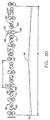
- the conductor-to-conductor spacing "S" varies in a relatively short distance (e.g., 76 mm, i.e. 3 inches).
- the pre-twist length of the wire may be random as well as uniform. If random pre-twisting is to be used in a paired cable, it is preferred that the cycling rate of conductor-to-conductor spacing be controlled to the extent that the distance it extends does not exceed about 1/8 wavelength of the maximum signal frequency.
- the cable pairs may be used alone or in combination with other cable pairs that may or may not have been paired in the same manner.
- the cable pairs may also be used in a variety of configurations, including, but not limited to, jacketed and unjacketed, shielded and unshielded.
- cable pairs configured in parallel or in a circular arrangement including oscillated as well as unidirectional modes, can be employed as required by their application.
- Oscillated constructions consist of cable pairs which sequentially rotate one direction, and then rotate in the other direction, over one oscillation period. Unidirectional and oscillated constructions are preferred for round cables, while paralleled pairs are desired for flat cables.
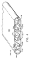
- FIG. 4 is a cross-sectional perspective view of a flat cable 210 containing four pre-twisted cable pairs 120 constructed according to the principles of the present invention used for the transmission of electrical signals.
- the outer jacket 220 is formed to create ridges 230 on the inside diameter of outer jacket 220. These ridges 230 define individual channels 240 for each of the cable pairs 120. Because the ridges 230 from the top and bottom of the outer jacket 220 do not actually join one another, the air dielectric is more readily maintained, resulting in improved electrical performance.
- flat cable 210 is constructed using a continuous-extrusion tubed jacketing process.
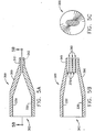
- Figures 5A-5C and 6A-6C show various views of a tip 300 and a die 400 which are used in the tubed jacketing process.
- Figure 7 is a cross-sectional view of the continuous-extrusion tubed jacketing process for a preferred flat cable with four cable pairs.
- the tapered end 310 of tip 300 extends all the way through the die 400, forming a face 430 such that the jacketing compound forms around the tip 300 rather than directly around the cable pairs 120.
- the outer jacketing compound "sets" or solidifies before the ridges 230 have a chance to come in contact with each other from opposite sides of the outer jacket 220.
- tip 300 is threaded and held in position by a threaded tube (not illustrated for the sake of clarity) by way of threads 330 which are disposed on the inner diameter of tip 300 and outer diameter of the threaded tube.
- Threads 330 are disposed on the inner diameter of tip 300 and outer diameter of the threaded tube.
- Positioning of the tip with standard round tips is generally not a critical issue, so tip 300 is merely threaded so that it snugly abuts the shoulder of the threaded tube.
- alignment between the tip 300 and the die 400 is more important, so appropriately selected washers or spacers (not shown) preferably are placed between the shoulder of the threaded tube and tip 300.
- tip 300 and die 400 may be used to hold tip 300 and die 400 in any desired orientation.
- tip 300 and die 400 are oriented flush to one another at face 430, as viewed in Figure 7.
- Tip 300 is inserted into die 400 at its tip receiving end 410. When the tip is in place, sufficient clearance is maintained between the outer surface 360 of tip 300 and the inner surface 420 of die 400 to provide an extrusion path 440 through which jacketing compound 432 may flow.
- the continuous-extrusion tubed jacketing process begins when a number of pre-twisted cable pairs 120 are fed through the cable pair receiving end 362 of tip 300.
- #24 AWG wire is used for each wire of the cable pairs: however, a variety of different sizes of wire can be utilized depending on the desired final product.
- Heat softened cable jacketing compound 432 is simultaneously fed through the extrusion path 440.
- the cable pairs 120 feed through the interior of tip 300 and approach the tapered end 310, they are directed into individual channels 370 for final alignment before joining the extruding cable jacketing compound to form the flat cable 210.
- Channels 370 are formed by barriers 380 present in the tapered end 310 of tip 300.
- the illustrated embodiment of this process is for forming a substantially oval-shaped flat cable, as determined by the shape and configuration of die tip 300 and die 400.
- the cable jacketing compound can be any material suitable for forming cable jackets, such as polyethylene or polyvinyl chloride. Since the preferred process is based on continuous extrusion, the typical head pressure usually does not exceed 0,138 Pa (2,000 psi).
- the preferred cable feed rate is 152,4 m (500 feet) per minute.
- the distance between the face 430 and quenching trough should be enough to hold the cable jacket shape, and good results have been achieved with a distance of 76 mm (3 inches). It will be understood that the preferred values of the aforementioned parameters are interdependent, and will change with different jacketing compounds, tooling materials and dimensions, wire diameters, feed rates, final cable shape, and orientation of the cable pairs.
- the above process results in a twisted-pair cable which is substantially improved over conventional twisted-pair cables.
- the unique cable cross-sectional structure provides improved electrical properties, and gives adequate cross-sectional strength to the cable, thereby minimizing the risk of buckling; which can cause pair-to-pair distortion during installation.
- stripping the jacket to expose the cable pairs is a one-step process, saving both time and energy for ease of installation and maintenance.
- the above process also minimizes handling of the individual cable pairs such that they are not physically brought together until the jacketing operation, where they are then fed directly into their individual channels. This feature allows the cable pairs to maintain virtually the same electrical performance and physical characteristics they exhibited after pairing.
- this continuous jacketing process be used with non-jacketed pairs of wires, but the present invention is not limited to this type of cable only. Individually jacketed or individually shielded pairs of wires can also be assembled using this technique, as can both shielded or non-shielded flat cable jackets.
Landscapes
- Communication Cables (AREA)
- Insulated Conductors (AREA)
Description
Claims (17)
- An individually twisted electrical cable pair, comprising:characterised in thata) a first insulated electrical wire (80) that is pre-twisted;b) a second insulated electrical wire (90), andc) said first and second insulated electrical wires (80, 90) being twisted together, thereby forming an electrical cable pair (120),
the second insulated electrical wire (90) is not pre-twisted. - The cable pair as recited in claim 1, wherein the pre-twist of said first insulated wire (80) is uniform throughout its length.
- The cable pair as recited in claim 2, wherein said first insulated wire (80) is pre-twisted at a first twist length, and said first and second insulated wires (80, 90) being configured such that both are twisted together at a combined uniform second twist length around a common axis, wherein the effective twist length of said first insulated wire (80) is different than the effective twist length of said second insulated wire (90).
- The cable pair as recited in claim 1, wherein the pre-twist of said first insulated wire (80) is not constant throughout its length.
- The cable pair as recited in claims 1, 2 or 4, wherein said first and second insulated wires (80, 90) are twisted together around a common axis.
- The cable pair as recited in any one of the preceding claims, wherein said first and second insulated wires (80, 90) are twisted together at a combined uniform twist length.
- The cable pair as recited in any one of the preceding claims, wherein the rotation of twist of said first insulated wire (80) is in the same direction as the rotation of twist of said cable pair (120).
- The cable pair as recited in any one of claims 1 to 6, wherein the rotation of twist of said first insulated wire (80) is in the opposite direction as the rotation of twist of said cable pair (120).
- The cable pair as recited in any one of the preceding claims, further comprising an outer jacket (220) of electrically insulating material that surrounds said cable pair (120).
- The cable pair as recited in any one of the preceding claims, further comprising an outer electrostatic shield of electrically conducting material that surrounds said cable pair (120).
- A multiple-paired electrical cable having a plurality of individually twisted electrical cable pairs (120) according to any one of the preceding claims, wherein said individually-twisted electrical cable pairs (120) are configured in parallel runs with respect to the axis of said multiple-paired electrical cable.
- The multiple-paired cable as recited in claim 11, wherein said multiple-paired cable is configured as a round cable.
- The multiple-paired cable as recited in claim 11, wherein said multiple-paired cable is configured as a flat cable (210).
- A multiple-paired electrical cable having a plurality of individually-twisted electrical cable pairs (120) according to any one of claims 1 to 10, wherein said individually-twisted electrical cable pairs (120) are configured in oscillating spiral runs in which said cable pairs (120) sequentially rotate clockwise, then rotate counterclockwise, per each cycle of oscillation along the axis of said multiple-paired electrical cable.
- The multiple-paired cable as recited in claim 14, wherein said clockwise rotation continues for approximately 720 degrees and said counterclockwise rotation continues for approximately 720 degrees.
- The multiple-paired cable as recited in claim 14 or 15, wherein said multiple-paired cable is configured as a round cable.
- The multiple-paired cable as recited in claim 16, wherein said plurality of individually-twisted cable pairs (120) have different twist lengths.
Applications Claiming Priority (3)
| Application Number | Priority Date | Filing Date | Title |
|---|---|---|---|
| US08/582,699 US5767441A (en) | 1996-01-04 | 1996-01-04 | Paired electrical cable having improved transmission properties and method for making same |
| US582699 | 1996-01-04 | ||
| PCT/US1997/000029 WO1997025725A2 (en) | 1996-01-04 | 1997-01-03 | Paired electrical cable having improved transmission properties and method for making same |
Publications (2)
| Publication Number | Publication Date |
|---|---|
| EP0871964A2 EP0871964A2 (en) | 1998-10-21 |
| EP0871964B1 true EP0871964B1 (en) | 2004-07-28 |
Family
ID=24330175
Family Applications (1)
| Application Number | Title | Priority Date | Filing Date |
|---|---|---|---|
| EP97901317A Expired - Lifetime EP0871964B1 (en) | 1996-01-04 | 1997-01-03 | Paired electrical cable having improved transmission properties and method for making same |
Country Status (15)
| Country | Link |
|---|---|
| US (2) | US5767441A (en) |
| EP (1) | EP0871964B1 (en) |
| AR (1) | AR005364A1 (en) |
| AT (1) | ATE272246T1 (en) |
| AU (1) | AU1524097A (en) |
| BR (1) | BR9706962A (en) |
| CA (1) | CA2242628C (en) |
| CO (1) | CO4520036A1 (en) |
| DE (1) | DE69730009T2 (en) |
| ID (2) | ID27079A (en) |
| MY (1) | MY132406A (en) |
| PE (1) | PE54698A1 (en) |
| TW (1) | TW318245B (en) |
| WO (1) | WO1997025725A2 (en) |
| ZA (1) | ZA9722B (en) |
Cited By (2)
| Publication number | Priority date | Publication date | Assignee | Title |
|---|---|---|---|---|
| US10186350B2 (en) | 2016-07-26 | 2019-01-22 | General Cable Technologies Corporation | Cable having shielding tape with conductive shielding segments |
| US10517198B1 (en) | 2018-06-14 | 2019-12-24 | General Cable Technologies Corporation | Cable having shielding tape with conductive shielding segments |
Families Citing this family (81)
| Publication number | Priority date | Publication date | Assignee | Title |
|---|---|---|---|---|
| US5821467A (en) * | 1996-09-11 | 1998-10-13 | Belden Wire & Cable Company | Flat-type communication cable |
| US6194663B1 (en) * | 1997-02-28 | 2001-02-27 | Lucent Technologies Inc. | Local area network cabling arrangement |
| FR2762133B1 (en) * | 1997-04-10 | 1999-06-11 | Alsthom Cge Alcatel | CONDUCTIVE WIRE, CABLE CONTAINING SAME, AND APPARATUS FOR MANUFACTURING SAME |
| US6608255B1 (en) * | 1997-05-22 | 2003-08-19 | Avaya Technology Corp. | Local area network cabling arrangement having improved capacitance unbalance and structural return loss |
| US6300687B1 (en) * | 1998-06-26 | 2001-10-09 | International Business Machines Corporation | Micro-flex technology in semiconductor packages |
| US6096977A (en) * | 1998-09-04 | 2000-08-01 | Lucent Technologies Inc. | High speed transmission patch cord cable |
| JP3278403B2 (en) | 1998-11-05 | 2002-04-30 | 株式会社キンレイ | Stranded wire machine |
| US6318062B1 (en) | 1998-11-13 | 2001-11-20 | Watson Machinery International, Inc. | Random lay wire twisting machine |
| US6288328B1 (en) * | 1999-03-19 | 2001-09-11 | Avaya Technology Corp. | Coaxial cable having effective insulated conductor rotation |
| US6209299B1 (en) | 1999-04-30 | 2001-04-03 | Thermoplastics Engineering Corp. | Double twist twinner with back-twist pay offs and intermediate capstan |
| US6570087B2 (en) * | 1999-05-25 | 2003-05-27 | Autosound 2000, Inc. | Delta magnetic de-fluxing for low noise signal cables |
| US6323427B1 (en) | 1999-05-28 | 2001-11-27 | Krone, Inc. | Low delay skew multi-pair cable and method of manufacture |
| WO2001038630A1 (en) * | 1999-11-24 | 2001-05-31 | Nordx/Cdt, Inc. | Double twist twisting machine |
| US6787694B1 (en) * | 2000-06-01 | 2004-09-07 | Cable Design Technologies, Inc. | Twisted pair cable with dual layer insulation having improved transmission characteristics |
| DE60233112D1 (en) * | 2001-02-28 | 2009-09-10 | Prysmian Spa | NACHRICHTENKABEL AND APPENDIX FOR THE MANUFACTURE OF SUCH CABLE |
| WO2002073634A2 (en) * | 2001-02-28 | 2002-09-19 | Pirelli S.P.A. | Communications cable, method and plant for manufacturing the same |
| AU2003235790A1 (en) * | 2002-01-07 | 2003-07-24 | Conectl Corporation | Improved communications cable and method for making same |
| US6959533B2 (en) | 2002-01-10 | 2005-11-01 | International Business Machines Corporation | Apparatus and method for producing twisted pair cables with reduced propagation delay and crosstalk |
| US7346552B1 (en) * | 2002-04-24 | 2008-03-18 | Cauldron Solutions, Llc | System and method for the enablement of electronic commerce in a content network |
| US7009105B2 (en) * | 2002-08-26 | 2006-03-07 | Hon Hai Precision Ind. Co., Ltd. | Bundle twisted-pair cable |
| US6825410B2 (en) * | 2002-08-26 | 2004-11-30 | Hon Hai Precision Ind. Co., Ltd. | Bundle twisted-pair cable |
| HK1079895A1 (en) | 2002-09-24 | 2006-04-13 | Adc Inc. | Communication wire |
| US7214880B2 (en) | 2002-09-24 | 2007-05-08 | Adc Incorporated | Communication wire |
| US20040055777A1 (en) | 2002-09-24 | 2004-03-25 | David Wiekhorst | Communication wire |
| US7019218B2 (en) * | 2002-10-16 | 2006-03-28 | Rgb Systems, Inc. | UTP cable apparatus with nonconducting core, and method of making same |
| US7078626B2 (en) * | 2004-03-12 | 2006-07-18 | Rgb Systems, Inc. | Cable apparatus for minimizing skew delay of analog signals and cross-talk from digital signals and method of making same |
| US7015397B2 (en) * | 2003-02-05 | 2006-03-21 | Belden Cdt Networking, Inc. | Multi-pair communication cable using different twist lay lengths and pair proximity control |
| US7221714B2 (en) * | 2003-05-12 | 2007-05-22 | Broadcom Corporation | Non-systematic and non-linear PC-TCM (Parallel Concatenate Trellis Coded Modulation) |
| US7244893B2 (en) * | 2003-06-11 | 2007-07-17 | Belden Technologies, Inc. | Cable including non-flammable micro-particles |
| US20040256139A1 (en) * | 2003-06-19 | 2004-12-23 | Clark William T. | Electrical cable comprising geometrically optimized conductors |
| CN103124189A (en) | 2003-07-11 | 2013-05-29 | 泛达公司 | Alien crosstalk suppression with enhanced patch cord |
| GB2419225B (en) * | 2003-07-28 | 2007-08-01 | Belden Cdt Networking Inc | Skew adjusted data cable |
| US7392647B2 (en) * | 2003-10-23 | 2008-07-01 | Commscope, Inc. Of North Carolina | Methods and apparatus for forming cable media |
| US6875928B1 (en) * | 2003-10-23 | 2005-04-05 | Commscope Solutions Properties, Llc | Local area network cabling arrangement with randomized variation |
| US8087433B2 (en) * | 2003-10-23 | 2012-01-03 | Commscope, Inc. Of North Carolina | Methods and apparatus for forming cable media |
| US7214884B2 (en) * | 2003-10-31 | 2007-05-08 | Adc Incorporated | Cable with offset filler |
| US7115815B2 (en) * | 2003-10-31 | 2006-10-03 | Adc Telecommunications, Inc. | Cable utilizing varying lay length mechanisms to minimize alien crosstalk |
| WO2006014889A1 (en) * | 2004-07-27 | 2006-02-09 | Belden Cdt Networking, Inc. | Dual-insulated, fixed together pair of conductors |
| US7064277B1 (en) | 2004-12-16 | 2006-06-20 | General Cable Technology Corporation | Reduced alien crosstalk electrical cable |
| US7238885B2 (en) * | 2004-12-16 | 2007-07-03 | Panduit Corp. | Reduced alien crosstalk electrical cable with filler element |
| US7317163B2 (en) * | 2004-12-16 | 2008-01-08 | General Cable Technology Corp. | Reduced alien crosstalk electrical cable with filler element |
| US7157644B2 (en) | 2004-12-16 | 2007-01-02 | General Cable Technology Corporation | Reduced alien crosstalk electrical cable with filler element |
| US7345243B2 (en) | 2004-12-17 | 2008-03-18 | Panduit Corp. | Communication cable with variable lay length |
| US7208683B2 (en) * | 2005-01-28 | 2007-04-24 | Belden Technologies, Inc. | Data cable for mechanically dynamic environments |
| EP1688968A1 (en) | 2005-02-04 | 2006-08-09 | Nexans | Helical electrical cable |
| US7173189B1 (en) * | 2005-11-04 | 2007-02-06 | Adc Telecommunications, Inc. | Concentric multi-pair cable with filler |
| US7329814B2 (en) * | 2005-12-29 | 2008-02-12 | Capricorn Audio Technologies Ltd | Electrical cable |
| US7271344B1 (en) * | 2006-03-09 | 2007-09-18 | Adc Telecommunications, Inc. | Multi-pair cable with channeled jackets |
| US7375284B2 (en) * | 2006-06-21 | 2008-05-20 | Adc Telecommunications, Inc. | Multi-pair cable with varying lay length |
| BRPI0707034A2 (en) | 2006-08-30 | 2011-04-12 | Afl Telecommunications Llc | method of manufacturing one cable, cable, double-tube down-cable and multi-tube down-cable |
| US20080060833A1 (en) * | 2006-09-12 | 2008-03-13 | Stephen Spruell | Multi-element twisted assembly and method using reverse axial torsion |
| US7696437B2 (en) * | 2006-09-21 | 2010-04-13 | Belden Technologies, Inc. | Telecommunications cable |
| US20080199134A1 (en) * | 2007-02-15 | 2008-08-21 | Superior Essex Communications Lp | System for identifying optical fibers and cables |
| WO2009009747A1 (en) * | 2007-07-12 | 2009-01-15 | Adc Telecommunications, Inc. | Telecommunication wire with low dielectric constant insulator |
| CA2692403C (en) | 2007-07-30 | 2016-08-30 | Southwire Company | Vibration resistant cable |
| US20100078196A1 (en) * | 2007-12-19 | 2010-04-01 | Mclaughlin Thomas | Category cable using dissimilar solid multiple layer |
| ES2372994T3 (en) * | 2008-06-02 | 2012-01-30 | Nexans | HELICIDALLY ROLLED ELECTRICAL CABLE. |
| US8063309B2 (en) * | 2008-06-06 | 2011-11-22 | Raymond & Lae Engineering, Inc. | Twisted leak detection cable |
| CA2724528C (en) * | 2008-07-03 | 2017-03-28 | Adc Telecommunications, Inc. | Telecommunications wire having a channeled dielectric insulator and methods for manufacturing the same |
| US8234910B2 (en) * | 2009-05-12 | 2012-08-07 | Raymond & Lae Engineering, Inc. | Aqueous chemical leak detection cable |
| US8431825B2 (en) | 2010-08-27 | 2013-04-30 | Belden Inc. | Flat type cable for high frequency applications |
| US8907211B2 (en) | 2010-10-29 | 2014-12-09 | Jamie M. Fox | Power cable with twisted and untwisted wires to reduce ground loop voltages |
| DE102011008275B4 (en) * | 2011-01-11 | 2016-02-18 | Brose Fahrzeugteile Gmbh & Co. Kommanditgesellschaft, Hallstadt | Sensor unit for contactless actuation of a vehicle door |
| KR101284495B1 (en) * | 2011-04-29 | 2013-07-16 | 성기철 | Wire electrode for electro discharge machining and thesame methode |
| CN102543319B (en) * | 2012-03-05 | 2013-06-05 | 上海易初电线电缆有限公司 | Material flow divider for flat cable |
| US9472320B2 (en) * | 2012-03-16 | 2016-10-18 | Wpfy, Inc. | Metal sheathed cable assembly with non-linear bonding/grounding conductor |
| JP5892072B2 (en) * | 2013-01-08 | 2016-03-23 | 日立金属株式会社 | Composite cable for vehicles |
| US11978571B2 (en) | 2013-05-03 | 2024-05-07 | Christopher M. Rey | Method of coiling a superconducting cable with clocking feature |
| US11133120B2 (en) * | 2014-04-30 | 2021-09-28 | Christopher Mark Rey | Superconductor cable or superconductor cable-in-conduit-conductor with clocking feature |
| US9601233B1 (en) * | 2015-05-28 | 2017-03-21 | Superior Essex International LP | Plenum rated twisted pair communication cables |
| JP6074634B1 (en) * | 2015-07-16 | 2017-02-08 | パナソニックIpマネジメント株式会社 | Electric cable |
| US10170220B2 (en) | 2016-01-27 | 2019-01-01 | Hitachi Cable America, Inc. | Extended frequency range balanced twisted pair transmission line or communication cable |
| DE112016006665T5 (en) | 2016-03-31 | 2018-12-20 | Autonetworks Technologies, Ltd. | communication cable |
| DE102016107645A1 (en) * | 2016-04-25 | 2017-10-26 | Yazaki Systems Technologies Gmbh | Electric cable and method of making such an electrical cable |
| CN108074676B (en) * | 2016-11-16 | 2022-08-02 | 安徽联嘉祥特种电缆有限公司 | Device and method for fixing twisted pair cable lay length |
| CN108074682B (en) * | 2016-11-16 | 2022-08-02 | 安徽联嘉祥特种电缆有限公司 | Twisted pair cable manufacturing equipment |
| DE112018000634T5 (en) * | 2017-02-01 | 2019-11-14 | Autonetworks Technologies, Ltd. | communication cable |
| CN111430083B (en) * | 2018-08-19 | 2021-12-10 | 重庆泰山电缆有限公司 | Insulated wire core stranding method |
| US11682501B2 (en) | 2020-09-22 | 2023-06-20 | Belden Inc. | Hybrid high frequency separator with parametric control ratios of conductive components |
| CN118522490A (en) * | 2024-04-29 | 2024-08-20 | 宁波达通电子线缆有限公司 | High-fidelity audio signal line |
| CN121011415B (en) * | 2025-10-27 | 2026-01-30 | 嘉兴翼波电子有限公司 | Cable insulation core wire production method based on heating power adjustment |
Family Cites Families (111)
| Publication number | Priority date | Publication date | Assignee | Title |
|---|---|---|---|---|
| US297175A (en) * | 1884-04-22 | shelbourne | ||
| US267279A (en) * | 1882-11-07 | Ments | ||
| US2732531A (en) | 1956-01-24 | Lockable electric connector | ||
| US1561495A (en) | 1924-11-01 | 1925-11-17 | Thompson Amos Cecil | Electrical connecter |
| US1629168A (en) * | 1926-01-12 | 1927-05-17 | Western Electric Co | Method of and apparatus for serving material upon alpha core |
| US1694056A (en) | 1927-06-16 | 1928-12-04 | Calkins Cecil | Locking plug for extension cords |
| US2026755A (en) | 1928-06-22 | 1936-01-07 | Albert A Stull | Electrical connection |
| US1941374A (en) | 1929-09-09 | 1933-12-26 | Sidney M Weisberg | Attachment plug |
| US2002558A (en) | 1931-12-24 | 1935-05-28 | Hubbell Inc Harvey | Interlocking connection |
| US1987772A (en) | 1933-01-03 | 1935-01-15 | Gustav A Eberhardt | Electric socket plug |
| US2049093A (en) | 1934-06-18 | 1936-07-28 | Thorin Harry | Electrical outlet plug |
| US2147525A (en) | 1937-04-26 | 1939-02-14 | Horace R Ellis | Electric plug and socket |
| US2180569A (en) | 1938-02-23 | 1939-11-21 | Walter H Walls | Electrical connector |
| US2166621A (en) | 1938-04-07 | 1939-07-18 | Sadye Budnick | Electric wiring connection |
| US2262272A (en) | 1938-11-28 | 1941-11-11 | Eaton George | Electric plug |
| US2215316A (en) | 1939-02-23 | 1940-09-17 | Monowatt Electric Corp | Electrical receptacle |
| US2198504A (en) | 1939-03-27 | 1940-04-23 | Austin R Pool | Spring lock for electrical contact plugs |
| US2261615A (en) | 1939-05-20 | 1941-11-04 | Cornwell Leroy | Electrical connector |
| US2213020A (en) | 1939-05-31 | 1940-08-27 | Louis A Scott | Electrical connection |
| US2199599A (en) | 1939-06-29 | 1940-05-07 | Stambaugh Sherwood | Electrical connector |
| US2307592A (en) | 1940-03-27 | 1943-01-05 | Arthur L Kuhlman | Electrical locking connector |
| GB561043A (en) | 1942-05-27 | 1944-05-03 | Henry John Modrey | Improvements in electrical plug and socket connectors |
| US2408551A (en) | 1943-09-20 | 1946-10-01 | Frank Louis | Self-latching electric plug |
| US2447597A (en) | 1945-08-28 | 1948-08-24 | Charles H Reed | Self-locking electric outlet and plug |
| US2479234A (en) | 1947-08-02 | 1949-08-16 | Trumbull Electric Mfg Co | Electric connector of the puller type |
| US2552061A (en) | 1947-12-17 | 1951-05-08 | Mcgill Mfg Company Inc | Safety electrical outlet |
| US2476510A (en) | 1948-04-17 | 1949-07-19 | Rosner Michael William | Electric plug |
| US2590505A (en) | 1949-08-10 | 1952-03-25 | Carlsen Otto | Interlock for electrical connectors |
| US2683864A (en) | 1950-03-03 | 1954-07-13 | Hubbell Inc Harvey | Locking means for electrical plugs |
| US2642264A (en) | 1951-04-06 | 1953-06-16 | Warren R Perry | Tire casing spreader |
| US2787653A (en) * | 1953-02-24 | 1957-04-02 | Anaconda Wire & Cable Co | Electric cables |
| US2771590A (en) | 1953-05-15 | 1956-11-20 | Benjamin F Nauslar | Interlocking electrical plug assembly |
| US2704831A (en) | 1954-05-24 | 1955-03-22 | Wilbur R Smith | Electric outlet having means to lock the prongs of an attachment plug therein |
| US2799009A (en) | 1954-12-30 | 1957-07-09 | Gen Electric | Locking means for separable electrical connectors |
| US2801394A (en) | 1955-04-25 | 1957-07-30 | Gen Motors Corp | Electrical terminal box |
| US2872654A (en) | 1955-08-04 | 1959-02-03 | Wilbur R Smith | Electrical outlet for three-prong locking plugs |
| US2946037A (en) | 1955-08-10 | 1960-07-19 | Ite Circuit Breaker Ltd | Electric receptacle |
| US2924806A (en) | 1956-01-23 | 1960-02-09 | Hubbell Inc Harvey | Electrical locking connector |
| US3067569A (en) * | 1957-02-28 | 1962-12-11 | Dow Chemical Co | Electrical conductors and methods of manufacture thereof |
| US3052079A (en) * | 1958-11-10 | 1962-09-04 | Western Electric Co | Apparatus for twisting strands |
| US2958724A (en) * | 1958-11-28 | 1960-11-01 | Perfection Mica Company | Electrical connector |
| US3066276A (en) | 1959-05-25 | 1962-11-27 | Hubbell Inc Harvey | Self locking receptacle and plug for electrical wiring devices |
| DK107567C (en) * | 1963-02-15 | 1967-06-12 | Ericsson Telefon Ab L M | Cable, preferably for transmitting telecommunication signals, and apparatus for use in its manufacture. |
| US3206709A (en) | 1963-08-12 | 1965-09-14 | Hubbell Inc Harvey | Interlocking electrical connectors |
| US3233204A (en) | 1963-09-17 | 1966-02-01 | Hubbell Inc Harvey | Automatic interlocking electrical connector |
| US3345603A (en) | 1965-09-02 | 1967-10-03 | Cohen Stanley Alan | Electrical plug key lock |
| US3350675A (en) | 1965-10-11 | 1967-10-31 | Hubbell Inc Harvey | Locking electrical connector |
| US3390368A (en) | 1966-06-30 | 1968-06-25 | Andrew M. Archer | Adaptor for converting electrical two-receptacle sockets into threereceptacle sockets |
| US3543218A (en) | 1968-03-08 | 1970-11-24 | Andrew M Archer | Safety connectors for electrical extension cords |
| US3489989A (en) | 1968-04-04 | 1970-01-13 | Chester J Robaczewski | Electrical plug locking device |
| FR2052029A5 (en) * | 1969-07-07 | 1971-04-09 | Nord Aviat | |
| US3611255A (en) | 1969-11-19 | 1971-10-05 | Lyall Electric | Moisture resistant electrical connector |
| US3643202A (en) | 1970-03-06 | 1972-02-15 | James A Coon | Quick release female plug |
| US3668607A (en) | 1971-01-25 | 1972-06-06 | Ivan A Farnworth | Electrical socket |
| US3691327A (en) | 1971-04-22 | 1972-09-12 | Abraham Chesler | Circuit-closing adapter |
| US3710304A (en) | 1971-05-05 | 1973-01-09 | J Warner | Locking electric plug |
| US3775726A (en) | 1971-09-13 | 1973-11-27 | R Gress | Safety receptacle |
| US3857996A (en) * | 1973-06-18 | 1974-12-31 | Anaconda Co | Flexible power cable |
| US3890025A (en) | 1973-08-02 | 1975-06-17 | Gene Louis Gray | Electrical plug lock |
| US3891289A (en) | 1974-02-07 | 1975-06-24 | Edward F Hanke | Lockable electrical outlet |
| IT1038150B (en) * | 1974-06-28 | 1979-11-20 | Fujikura Ltd | METHOD AND EQUIPMENT FOR CORDING INSULATED CONDUCTORS IN TWO PAIRS INTENDED TO BE USED IN MULTICONDUCTOR COMMUNICATION CABLES |
| US3942856A (en) | 1974-12-23 | 1976-03-09 | Mindheim Daniel J | Safety socket assembly |
| FR2299366A1 (en) | 1975-01-31 | 1976-08-27 | Rhone Poulenc Ind | NEW THICKENING COMPOSITION BASED ON HETEROPOLYSACCHARIDES |
| CA1103494A (en) * | 1976-06-24 | 1981-06-23 | Dennis L. Lewis | Optical fibre cables and their manufacture |
| US4061409A (en) | 1976-11-10 | 1977-12-06 | Herbert Shipley Bealmear | Releasable locking means for two part electric connector |
| DE2702182C3 (en) * | 1977-01-20 | 1981-07-02 | Lynenwerk Gmbh & Co Kg, 5180 Eschweiler | Process for the production of electrical cables with strain relief |
| US4316493B1 (en) | 1977-08-15 | 1997-06-24 | Newell Operating Co | Vertical blind controls |
| US4136919A (en) | 1977-11-04 | 1979-01-30 | Howard Guy W | Electrical receptacle with releasable locking means |
| US4167658A (en) | 1978-03-20 | 1979-09-11 | Sherman Robert S | Safety and security outlet |
| JPS593011B2 (en) * | 1978-05-23 | 1984-01-21 | 株式会社フジクラ | flat power supply cable |
| US4182105A (en) * | 1978-05-26 | 1980-01-08 | Yoshida Kogyo Kabushiki Kaisha | Method of manufacturing collectively stranded wires for communication cables |
| IT1166829B (en) * | 1979-05-18 | 1987-05-06 | Pirelli | PROCEDURE AND PLANT FOR THE MANUFACTURE OF TELECOMMUNICATIONS CABLES |
| US4312554A (en) | 1980-01-30 | 1982-01-26 | Wang Wei Kung | Electric safety socket with internal locking means |
| US4461923A (en) * | 1981-03-23 | 1984-07-24 | Virginia Patent Development Corporation | Round shielded cable and modular connector therefor |
| US4516922A (en) * | 1981-09-29 | 1985-05-14 | At&T Technologies, Inc. | Hybrid apparatus for insulating conductors |
| US4404424A (en) * | 1981-10-15 | 1983-09-13 | Cooper Industries, Inc. | Shielded twisted-pair flat electrical cable |
| DE3150031A1 (en) * | 1981-12-17 | 1983-06-23 | H. Stoll Gmbh & Co, 7410 Reutlingen | HIGHLY FLEXIBLE INSULATED ELECTRIC CABLE |
| GB2116901B (en) * | 1982-03-04 | 1986-10-29 | Standard Telephones Cables Ltd | Extruding a dielectric sheath around a joint in an optical fibre cable |
| US4445593A (en) * | 1982-10-15 | 1984-05-01 | Siecor Corporation | Flat type feeder cable |
| US4579410A (en) | 1983-02-15 | 1986-04-01 | Leonard Soloman | Security attachment for electrical plug |
| CA1211179A (en) | 1983-10-28 | 1986-09-09 | Fernand H. Poulin | Electrical receptacle |
| US4568507A (en) * | 1983-12-27 | 1986-02-04 | Northern Telecom Limited | Jacketing of telecommunications cable cores |
| DE3405852A1 (en) * | 1984-02-15 | 1985-08-22 | Siemens AG, 1000 Berlin und 8000 München | MULTI-CORE FLEXIBLE ELECTRICAL CABLE |
| US4505222A (en) * | 1984-03-15 | 1985-03-19 | Celanese Corporation | Extrusion coating apparatus |
| US4533421A (en) * | 1984-04-25 | 1985-08-06 | Pattridge Post Tension, Inc. | Method for making a lap seam extruded tendon |
| DE3432600A1 (en) * | 1984-08-31 | 1986-03-13 | Siemens AG, 1000 Berlin und 8000 München | FLEXIBLE ELECTRICAL CONTROL LINE |
| CA1222362A (en) * | 1985-02-01 | 1987-06-02 | Northern Telecom Limited | Insulating electrical conductor |
| US4627681A (en) | 1985-02-15 | 1986-12-09 | Douglas Hong | Locking electrical connector |
| US4680423A (en) * | 1985-03-04 | 1987-07-14 | Amp Incorporated | High performance flat cable |
| US4734544A (en) * | 1986-10-29 | 1988-03-29 | Noel Lee | Signal cable having an internal dielectric core |
| US4754102A (en) * | 1987-06-02 | 1988-06-28 | Dzurak Thomas J | Directional interconnection cable for high fidelity signal transmission |
| US4777325A (en) * | 1987-06-09 | 1988-10-11 | Amp Incorporated | Low profile cables for twisted pairs |
| US4784611A (en) | 1987-08-18 | 1988-11-15 | Poulin Fernand H | Locking plug |
| US4820187A (en) | 1987-10-16 | 1989-04-11 | May Donald M | Tamper-proof electrical receptacle |
| DE3744465C1 (en) * | 1987-12-23 | 1989-02-09 | Siemens Ag | Device and method for producing the insulation layer of a line |
| US4867697A (en) | 1988-07-12 | 1989-09-19 | Al-Ray Development | Self-locking, two-part electrical connector employing receptacle with spring-biased wedge for expanding plug's blades |
| US4969833A (en) | 1988-10-04 | 1990-11-13 | Lindow Edgar J | Permanently attachable key-activated on/off switch |
| US4937401A (en) * | 1989-01-05 | 1990-06-26 | Noel Lee | Signal cable assembly including bundles of wire strands of different gauges |
| US4909749A (en) | 1989-01-27 | 1990-03-20 | Jason Long | Electrical sockets |
| US4925396A (en) | 1989-06-30 | 1990-05-15 | Grover Dennis L | Latching mechanism for electrical plugs |
| US4945189A (en) * | 1989-08-09 | 1990-07-31 | Palmer Donald E | Asymmetric audio cable for high fidelity signals |
| US5082450A (en) | 1990-11-05 | 1992-01-21 | Warren Sr Charles C | Safety plug with ground lock and prong locks |
| US5132488A (en) * | 1991-02-21 | 1992-07-21 | Northern Telecom Limited | Electrical telecommunications cable |
| US5129836A (en) | 1991-06-24 | 1992-07-14 | Ursich Nels E | Self-locking female receptor for electrical cord |
| JP2672749B2 (en) * | 1991-08-06 | 1997-11-05 | 住友電気工業株式会社 | Metal cord and composite of this and rubber |
| US5286213A (en) | 1993-01-27 | 1994-02-15 | Raymond Altergott | Locking receptacle |
| US5530556A (en) | 1993-02-10 | 1996-06-25 | Canon Kabushiki Kaisha | Recording apparatus with dual independent control limits |
| US5352132A (en) | 1993-06-14 | 1994-10-04 | Keefe Michael S O | Extension cord |
| US5336103A (en) | 1993-08-26 | 1994-08-09 | Herboldsheimer John D | Female socket-based male plug locking device |
| US5424491A (en) * | 1993-10-08 | 1995-06-13 | Northern Telecom Limited | Telecommunications cable |
| US5493071A (en) * | 1994-11-10 | 1996-02-20 | Berk-Tek, Inc. | Communication cable for use in a plenum |
-
1996
- 1996-01-04 US US08/582,699 patent/US5767441A/en not_active Expired - Lifetime
- 1996-12-26 ID IDP20001021A patent/ID27079A/en unknown
- 1996-12-26 ID IDP963936A patent/ID17205A/en unknown
- 1996-12-31 MY MYPI96005567A patent/MY132406A/en unknown
-
1997
- 1997-01-02 ZA ZA9700022A patent/ZA9722B/en unknown
- 1997-01-03 AT AT97901317T patent/ATE272246T1/en not_active IP Right Cessation
- 1997-01-03 WO PCT/US1997/000029 patent/WO1997025725A2/en not_active Ceased
- 1997-01-03 AR ARP970100034A patent/AR005364A1/en unknown
- 1997-01-03 DE DE69730009T patent/DE69730009T2/en not_active Expired - Fee Related
- 1997-01-03 EP EP97901317A patent/EP0871964B1/en not_active Expired - Lifetime
- 1997-01-03 CO CO97000124A patent/CO4520036A1/en unknown
- 1997-01-03 CA CA002242628A patent/CA2242628C/en not_active Expired - Fee Related
- 1997-01-03 AU AU15240/97A patent/AU1524097A/en not_active Abandoned
- 1997-01-03 BR BR9706962-0A patent/BR9706962A/en not_active IP Right Cessation
- 1997-01-06 PE PE1997000002A patent/PE54698A1/en not_active Application Discontinuation
- 1997-03-06 TW TW086102744A patent/TW318245B/zh active
-
1998
- 1998-01-08 US US09/003,942 patent/US6254924B1/en not_active Expired - Lifetime
Cited By (2)
| Publication number | Priority date | Publication date | Assignee | Title |
|---|---|---|---|---|
| US10186350B2 (en) | 2016-07-26 | 2019-01-22 | General Cable Technologies Corporation | Cable having shielding tape with conductive shielding segments |
| US10517198B1 (en) | 2018-06-14 | 2019-12-24 | General Cable Technologies Corporation | Cable having shielding tape with conductive shielding segments |
Also Published As
| Publication number | Publication date |
|---|---|
| ATE272246T1 (en) | 2004-08-15 |
| PE54698A1 (en) | 1998-09-26 |
| CA2242628C (en) | 2002-08-13 |
| CO4520036A1 (en) | 1997-10-15 |
| DE69730009T2 (en) | 2005-07-21 |
| US6254924B1 (en) | 2001-07-03 |
| WO1997025725A3 (en) | 1997-10-30 |
| AU1524097A (en) | 1997-08-01 |
| ID17205A (en) | 1997-12-11 |
| ID27079A (en) | 1997-12-11 |
| ZA9722B (en) | 1997-10-09 |
| DE69730009D1 (en) | 2004-09-02 |
| TW318245B (en) | 1997-10-21 |
| US5767441A (en) | 1998-06-16 |
| BR9706962A (en) | 2000-10-24 |
| AR005364A1 (en) | 1999-04-28 |
| EP0871964A2 (en) | 1998-10-21 |
| WO1997025725A2 (en) | 1997-07-17 |
| CA2242628A1 (en) | 1997-07-17 |
| MY132406A (en) | 2007-10-31 |
Similar Documents
| Publication | Publication Date | Title |
|---|---|---|
| US5767441A (en) | Paired electrical cable having improved transmission properties and method for making same | |
| US6403887B1 (en) | High speed data transmission cable and method of forming same | |
| EP0117943B1 (en) | Method of manufacturing a communication cable | |
| US7946031B2 (en) | Method for forming an enhanced communication cable | |
| US6365836B1 (en) | Cross web for data grade cables | |
| KR100708407B1 (en) | Low delay skew multi-pair cable and method of manufacturing the same | |
| US7977575B2 (en) | High performance data cable | |
| US5796046A (en) | Communication cable having a striated cable jacket | |
| CA2135952C (en) | Methods of making telecommunications cable | |
| CN107230525B (en) | Ultrahigh frequency digital communication cable and preparation method thereof | |
| US7390971B2 (en) | Unsheilded twisted pair cable and method for manufacturing the same | |
| US11087904B2 (en) | Multicore cable | |
| US7214882B2 (en) | Communications cable, method and plant for manufacturing the same | |
| WO2002073634A2 (en) | Communications cable, method and plant for manufacturing the same | |
| JPH1196837A (en) | communication cable | |
| CA2277655C (en) | Cross web for data grade cables | |
| JP2000195346A (en) | Communication cable | |
| JPS5858769B2 (en) | Manufacturing equipment for bulk insulated communication cables | |
| TWM643422U (en) | multi-channel cable assembly | |
| EP1702343A1 (en) | Multipolar cable for transmitting energy and/or signals, method and apparatus for the production thereof | |
| JPS5826125B2 (en) | Bulk insulation coated cable manufacturing equipment |
Legal Events
| Date | Code | Title | Description |
|---|---|---|---|
| PUAI | Public reference made under article 153(3) epc to a published international application that has entered the european phase |
Free format text: ORIGINAL CODE: 0009012 |
|
| 17P | Request for examination filed |
Effective date: 19980731 |
|
| AK | Designated contracting states |
Kind code of ref document: A2 Designated state(s): AT BE CH DE DK ES FI FR GB GR IE IT LI LU MC NL PT SE |
|
| RIN1 | Information on inventor provided before grant (corrected) |
Inventor name: RUTKOSKI, LAVERN, P. Inventor name: BERELSMAN, TIMOTHY Inventor name: POULSEN, JEFFREY, ALAN Inventor name: BROREIN, WILLIAM, JACOB |
|
| RAP1 | Party data changed (applicant data changed or rights of an application transferred) |
Owner name: GENERAL CABLE TECHNOLOGIES CORPORATION |
|
| 17Q | First examination report despatched |
Effective date: 20000215 |
|
| GRAP | Despatch of communication of intention to grant a patent |
Free format text: ORIGINAL CODE: EPIDOSNIGR1 |
|
| GRAS | Grant fee paid |
Free format text: ORIGINAL CODE: EPIDOSNIGR3 |
|
| GRAA | (expected) grant |
Free format text: ORIGINAL CODE: 0009210 |
|
| AK | Designated contracting states |
Kind code of ref document: B1 Designated state(s): AT BE CH DE DK ES FI FR GB GR IE IT LI LU MC NL PT SE |
|
| PG25 | Lapsed in a contracting state [announced via postgrant information from national office to epo] |
Ref country code: IT Free format text: LAPSE BECAUSE OF FAILURE TO SUBMIT A TRANSLATION OF THE DESCRIPTION OR TO PAY THE FEE WITHIN THE PRESCRIBED TIME-LIMIT;WARNING: LAPSES OF ITALIAN PATENTS WITH EFFECTIVE DATE BEFORE 2007 MAY HAVE OCCURRED AT ANY TIME BEFORE 2007. THE CORRECT EFFECTIVE DATE MAY BE DIFFERENT FROM THE ONE RECORDED. Effective date: 20040728 Ref country code: FR Free format text: LAPSE BECAUSE OF FAILURE TO SUBMIT A TRANSLATION OF THE DESCRIPTION OR TO PAY THE FEE WITHIN THE PRESCRIBED TIME-LIMIT Effective date: 20040728 Ref country code: FI Free format text: LAPSE BECAUSE OF FAILURE TO SUBMIT A TRANSLATION OF THE DESCRIPTION OR TO PAY THE FEE WITHIN THE PRESCRIBED TIME-LIMIT Effective date: 20040728 Ref country code: BE Free format text: LAPSE BECAUSE OF FAILURE TO SUBMIT A TRANSLATION OF THE DESCRIPTION OR TO PAY THE FEE WITHIN THE PRESCRIBED TIME-LIMIT Effective date: 20040728 Ref country code: AT Free format text: LAPSE BECAUSE OF FAILURE TO SUBMIT A TRANSLATION OF THE DESCRIPTION OR TO PAY THE FEE WITHIN THE PRESCRIBED TIME-LIMIT Effective date: 20040728 |
|
| REG | Reference to a national code |
Ref country code: GB Ref legal event code: FG4D |
|
| REG | Reference to a national code |
Ref country code: CH Ref legal event code: EP |
|
| REG | Reference to a national code |
Ref country code: IE Ref legal event code: FG4D |
|
| REF | Corresponds to: |
Ref document number: 69730009 Country of ref document: DE Date of ref document: 20040902 Kind code of ref document: P |
|
| PG25 | Lapsed in a contracting state [announced via postgrant information from national office to epo] |
Ref country code: SE Free format text: LAPSE BECAUSE OF FAILURE TO SUBMIT A TRANSLATION OF THE DESCRIPTION OR TO PAY THE FEE WITHIN THE PRESCRIBED TIME-LIMIT Effective date: 20041028 Ref country code: GR Free format text: LAPSE BECAUSE OF FAILURE TO SUBMIT A TRANSLATION OF THE DESCRIPTION OR TO PAY THE FEE WITHIN THE PRESCRIBED TIME-LIMIT Effective date: 20041028 Ref country code: DK Free format text: LAPSE BECAUSE OF FAILURE TO SUBMIT A TRANSLATION OF THE DESCRIPTION OR TO PAY THE FEE WITHIN THE PRESCRIBED TIME-LIMIT Effective date: 20041028 |
|
| REG | Reference to a national code |
Ref country code: CH Ref legal event code: NV Representative=s name: RITSCHER & PARTNER AG |
|
| PG25 | Lapsed in a contracting state [announced via postgrant information from national office to epo] |
Ref country code: ES Free format text: LAPSE BECAUSE OF FAILURE TO SUBMIT A TRANSLATION OF THE DESCRIPTION OR TO PAY THE FEE WITHIN THE PRESCRIBED TIME-LIMIT Effective date: 20041108 |
|
| PGFP | Annual fee paid to national office [announced via postgrant information from national office to epo] |
Ref country code: MC Payment date: 20041229 Year of fee payment: 9 Ref country code: GB Payment date: 20041229 Year of fee payment: 9 |
|
| PGFP | Annual fee paid to national office [announced via postgrant information from national office to epo] |
Ref country code: NL Payment date: 20050103 Year of fee payment: 9 |
|
| PGFP | Annual fee paid to national office [announced via postgrant information from national office to epo] |
Ref country code: FR Payment date: 20050110 Year of fee payment: 9 |
|
| PGFP | Annual fee paid to national office [announced via postgrant information from national office to epo] |
Ref country code: IE Payment date: 20050112 Year of fee payment: 9 |
|
| PGFP | Annual fee paid to national office [announced via postgrant information from national office to epo] |
Ref country code: LU Payment date: 20050113 Year of fee payment: 9 |
|
| PGFP | Annual fee paid to national office [announced via postgrant information from national office to epo] |
Ref country code: CH Payment date: 20050117 Year of fee payment: 9 |
|
| PLBE | No opposition filed within time limit |
Free format text: ORIGINAL CODE: 0009261 |
|
| STAA | Information on the status of an ep patent application or granted ep patent |
Free format text: STATUS: NO OPPOSITION FILED WITHIN TIME LIMIT |
|
| 26N | No opposition filed |
Effective date: 20050429 |
|
| EN | Fr: translation not filed | ||
| PG25 | Lapsed in a contracting state [announced via postgrant information from national office to epo] |
Ref country code: DE Free format text: LAPSE BECAUSE OF NON-PAYMENT OF DUE FEES Effective date: 20050802 |
|
| REG | Reference to a national code |
Ref country code: HK Ref legal event code: WD Ref document number: 1016741 Country of ref document: HK |
|
| PG25 | Lapsed in a contracting state [announced via postgrant information from national office to epo] |
Ref country code: IE Free format text: LAPSE BECAUSE OF NON-PAYMENT OF DUE FEES Effective date: 20060103 Ref country code: GB Free format text: LAPSE BECAUSE OF NON-PAYMENT OF DUE FEES Effective date: 20060103 |
|
| PG25 | Lapsed in a contracting state [announced via postgrant information from national office to epo] |
Ref country code: MC Free format text: LAPSE BECAUSE OF NON-PAYMENT OF DUE FEES Effective date: 20060131 Ref country code: LU Free format text: LAPSE BECAUSE OF NON-PAYMENT OF DUE FEES Effective date: 20060131 Ref country code: LI Free format text: LAPSE BECAUSE OF NON-PAYMENT OF DUE FEES Effective date: 20060131 Ref country code: CH Free format text: LAPSE BECAUSE OF NON-PAYMENT OF DUE FEES Effective date: 20060131 |
|
| PG25 | Lapsed in a contracting state [announced via postgrant information from national office to epo] |
Ref country code: NL Free format text: LAPSE BECAUSE OF NON-PAYMENT OF DUE FEES Effective date: 20060801 |
|
| REG | Reference to a national code |
Ref country code: CH Ref legal event code: PL |
|
| GBPC | Gb: european patent ceased through non-payment of renewal fee |
Effective date: 20060103 |
|
| NLV4 | Nl: lapsed or anulled due to non-payment of the annual fee |
Effective date: 20060801 |
|
| REG | Reference to a national code |
Ref country code: IE Ref legal event code: MM4A |
|
| PG25 | Lapsed in a contracting state [announced via postgrant information from national office to epo] |
Ref country code: PT Free format text: LAPSE BECAUSE OF NON-PAYMENT OF DUE FEES Effective date: 20041228 |