EP0871844B1 - Hahnspannvorrichtung und verschlussverriegelungs-vorrichtung für feuerwaffen mit einem spannhebel - Google Patents
Hahnspannvorrichtung und verschlussverriegelungs-vorrichtung für feuerwaffen mit einem spannhebel Download PDFInfo
- Publication number
- EP0871844B1 EP0871844B1 EP97903754A EP97903754A EP0871844B1 EP 0871844 B1 EP0871844 B1 EP 0871844B1 EP 97903754 A EP97903754 A EP 97903754A EP 97903754 A EP97903754 A EP 97903754A EP 0871844 B1 EP0871844 B1 EP 0871844B1
- Authority
- EP
- European Patent Office
- Prior art keywords
- lever
- bolt
- hammer
- pin
- firearm
- Prior art date
- Legal status (The legal status is an assumption and is not a legal conclusion. Google has not performed a legal analysis and makes no representation as to the accuracy of the status listed.)
- Expired - Lifetime
Links
- 238000010304 firing Methods 0.000 claims abstract description 22
- 239000000463 material Substances 0.000 claims description 10
- 230000000295 complement effect Effects 0.000 claims description 5
- 206010061258 Joint lock Diseases 0.000 abstract 2
- 229910000831 Steel Inorganic materials 0.000 description 2
- 239000007789 gas Substances 0.000 description 2
- 239000010959 steel Substances 0.000 description 2
- 229910000838 Al alloy Inorganic materials 0.000 description 1
- 230000000694 effects Effects 0.000 description 1
- 230000000630 rising effect Effects 0.000 description 1
Images





Classifications
-
- F—MECHANICAL ENGINEERING; LIGHTING; HEATING; WEAPONS; BLASTING
- F41—WEAPONS
- F41A—FUNCTIONAL FEATURES OR DETAILS COMMON TO BOTH SMALLARMS AND ORDNANCE, e.g. CANNONS; MOUNTINGS FOR SMALLARMS OR ORDNANCE
- F41A19/00—Firing or trigger mechanisms; Cocking mechanisms
- F41A19/06—Mechanical firing mechanisms, e.g. counterrecoil firing, recoil actuated firing mechanisms
- F41A19/42—Mechanical firing mechanisms, e.g. counterrecoil firing, recoil actuated firing mechanisms having at least one hammer
- F41A19/43—Mechanical firing mechanisms, e.g. counterrecoil firing, recoil actuated firing mechanisms having at least one hammer in bolt-action guns
- F41A19/47—Cocking mechanisms
-
- F—MECHANICAL ENGINEERING; LIGHTING; HEATING; WEAPONS; BLASTING
- F41—WEAPONS
- F41A—FUNCTIONAL FEATURES OR DETAILS COMMON TO BOTH SMALLARMS AND ORDNANCE, e.g. CANNONS; MOUNTINGS FOR SMALLARMS OR ORDNANCE
- F41A3/00—Breech mechanisms, e.g. locks
- F41A3/12—Bolt action, i.e. the main breech opening movement being parallel to the barrel axis
- F41A3/14—Rigid bolt locks, i.e. having locking elements rigidly mounted on the bolt or bolt handle and on the barrel or breech-housing respectively
- F41A3/32—Rigid bolt locks, i.e. having locking elements rigidly mounted on the bolt or bolt handle and on the barrel or breech-housing respectively the bolt being rocked about a notional axis transverse to the barrel axis
-
- F—MECHANICAL ENGINEERING; LIGHTING; HEATING; WEAPONS; BLASTING
- F41—WEAPONS
- F41C—SMALLARMS, e.g. PISTOLS, RIFLES; ACCESSORIES THEREFOR
- F41C7/00—Shoulder-fired smallarms, e.g. rifles, carbines, shotguns
- F41C7/06—Lever-action guns, i.e. guns having a rocking lever for loading or cocking
Definitions
- the present invention relates to an improved lever action firearm.
- Lever action firearms have included lever locking systems (US Patent Nos. 10,535 and 502,018).
- Prior lever action rifles have used linkages to keep the bolt in proper position at the rear of the barrel during the forces generated from firing.
- DE -A- 612 895 discloses a canonic lever action firearm comprising a pivotal hammer 4, a cocking lever 6, a crosspin 7, and further including: a configured hammer surface 3, and hammer engaging means on the cocking lever 6,8.
- US-A- 2 606 383 discloses in a lever operated rifle bolt action, a receiver having a bore extending longitudinally therethrough and a transversely extending aperture adjacent the front end thereof, a bolt longitudinally slidable in said bore toward and away from a breech closing position therein and having near its front end a transversely extending aperture registering with the aperture in said receiver when said bolt is in said breech closing position, a frame attached to said receiver and extending longitudinally of the latter in spaced relationship thereto, a hand lever pivotally mounted intermediate its length on said frame for swinging movement about an axis transverse to the frame and having one end disposed within the latter and adjacent to the bolt means, including a link connecting one end of said lever to said bolt for movement of the latter toward and away from said breech closing position upon swinging movement of said hand lever, said means providing a limited freedom of swinging movement of said hand lever without moving said bolt when said bolt is in said breech closing position, a locking pin slidably received in
- the present invention is an improvement, in lever action firearms in which the cocking lever is pivotally connected to the bolt through a relatively short link and in which the cocking lever or side pin extension thereof is engageable with a hammer surface to rotate the hammer back during opening of the lever.
- a receiver recess interact to cause the bolt to be swung: (1) upwardly and forwardly during the loading movement of the cocking lever; (2) downwardly and rearwardly as the bolt moves rearwardly immediately after firing; and (3) further downwardly and rearwardly as the cocking lever is manually swung to unload the firearm.
- the cocking lever arm has one or more hammer engaging -surfaces to engage the hammer to cause the hammer to be rotated back a sufficient distance during unloading to allow the hammer to move forward a short distance to engage the sear during loading.
- Such relationship between the cocking lever and hammer allows the hammer to move the lever and its attached bolt forward under certain conditions to assure closing of the bolt before firing.
- the bolt engages the receiver along angled sliding surfaces in its locked position which causes, during firing and immediately thereafter, the bolt to move rearwardly and downwardly to increase the force necessary to unlock the bolt thereby resisting unlocking when breach pressures are at their peak during firing. Because of the shallow angles on this locking projection lug, most of this force is against the receiver with a small amount of force constituting downthrust.
- the shape, configuration and proportion of the lever arm and link are such that immediately following firing when the rear of the bolt is moved downwardly a force is required to cause the lever and link to move from one side of such center line to the other side. During this period the bolt lock operates on a toggle joint or over-center principle.
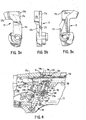
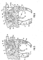
- firearm 10 includes stock 11, receiver 12 with its pin section 9, bolt 14, angled bolt locking surface 14c on bolt projection lug 141, firing pin 15, cocking and bolt control lever 6, hammer 17, hammer striking surface 17c in hammer recess 17r, trigger 18 and lever housing 19. Also shown are lever pivot pin 13, cartridge case C, receiver recess 12r, receiver cross pin locking shoulder 9s and forward and rearward housing cross pins 21 and 22 (see Fig.5).
- hammer 17 includes hammer body 17b, hammer recess 17r and hammer cam surface 17s.
- Cocking lever 16 pivoted about lever pivot pin 13 on housing 19, includes handle portion 16h and cocking arcuate upper arm piece 16p with its bifurcated right and left end prongs 24, 25, respectively.
- Lever 16 is connected to bolt 14 by toggle link 28.
- Cocking arcuate arm piece 16p carries hammer stop pin 29 which includes stem 29s and pin head 29h (see Fig. 12). Pin head 29h projects from the side of lever arcuate piece 16p (see Fig. 12).
- Hammer stop pin 29 functions to engage cam and hammer surface 17s in hammer recess 17r to rotate hammer 17 rearward to its full rearward position when lever. 16 is swung down to unload firearm 10. Initially stop pin 29 engages hammer surface 17s to rotate hammer 17.
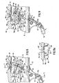
- Fig. 7 shows an alternative embodiment in which no hammer stop pin is employed. Instead, lever arm 16p' including right end prong 25 is made of a harder material permitting end prong 25 to repeatedly engage hammer surface 17s without excessive force to effect hammer rotation in the same manner as pin 29 and the end prong 24 performed in the prior embodiment. Finally, surface 16z of arm 16p engages housing stop 19e.
- connector pin secures receiver 12 to housing 19. Lever end prong 24 extends downwardly a sufficient distance to engage stop 19e when lever 16 is fully opened with bolt 14 fully retracted.
- cocking lever 16 is swung in the opposite direction upwardly to cause bolt 14 to capture a new cartridge for chambering.
- bolt 14 is adjacent to and in contact with cartridge case C at point P (see Fig. 1).
- cocking lever 21 does not fully complete its upward swing during loading but instead stops short of casing C in an intermediate position, leaving bolt 14 spaced from cartridge C, and when trigger 18 is thereafter pulled, the falling hammer 17 and its surface 17s engages hammer stop pin 29 and under urging of hammer spring 51 moves lever 16 (and connected bolt 14) forward against cartridge C.
- Such an intermediate position cannot be reached until hammer stop pin 29 has moved forward of hammer surface 17s.
- Movement from an intermediate position to a fire position is accomplished by hammer surface 17s engaging pin head 29h projecting from the side of lever 16.
- Pin 29 and its head 29h are located on arcuate arm prong 24 in such a position that as hammer 17 falls under the urging of spring 51 it causes lever 16 to move upwardly and forwardly until bolt 14 is locked against cartridge case C at point P.
- This action of the hammer 17 on head 29h of stop pin 29 assures that bolt 14 is in its closed proper ready-to-fire position prior to actual firing of firearm 10.
- Hammer 17 cannot strike firing pin 15 (bolt 14) until lever 16 is a few thousandths of an inch from being fully closed (i.e., 0.040-0.50 inches).
- lever 16 has a fully open position (Fig. 2) with pin 29 against housing stop surface 19e; a fully closed position (Fig. 1) in which bolt 14 is in full contact at point P against cartridge case C and lever 16 can also have a temporary less-than-fully-closed position in which bolt 14 is touching cartridge case C or spaced a short distance from case C.
- a fully open position FIG. 2
- lever 16 can also have a temporary less-than-fully-closed position in which bolt 14 is touching cartridge case C or spaced a short distance from case C.
- Pin head 29h is engaged by hammer surface 175 during hammer 17's travel after being released by sear 52 thus moving lever 16 (and bolt 14) forward to assure bolt 14 is closed and locked prior to firing.
- the rear surface 14s of bolt 14 is slightly spaced from rear receiver wall 11w (Fig. 7) of receiver 12. This clearance, assured by hammer stop pin 29 contacting seat 19e, prevents strain on the forward ends 24, 25 of forward lever portion 16p of lever 16.
- the system for resisting the unlocking of bolt 14 upon firing includes lever arm portion 16p with its forward end bifurcated right and left arm prongs 24, 25, respectively; the lever arm end pin 26; link 28 sandwiched between lever arm prongs 24, 25; and bolt cross pin 31.
- Bolt cross pin 31 is located in bolt lower portion 35. Elongated link slot 28s rides over arm pin 26. Movement toward a bolt lock position is attained when lever arm prongs 24, 25 are moved forward until the center 26c of arm end pin 26 is forward of line L as shown in Figs. 1, 4 and 8.
- Line L is the center line between center 31c of bolt cross pin 31 and the center 13c of stationary housing pin 13.
- lever arm portion 16p with its end prongs 24, 25 and connected link 28 are swung and oriented to positions where center line LL and line L becomes superimposed upon one another.
- Line LL is the line between pin center 31c and pin center 26c.
- lever 16 continues its forward and upward movement until it reaches the fully locked position (Figs. 1, 4 and 8).
- tail 28t on link 28 engages pin 21 to limit arm portion 16p movement and at this point detent 45 snaps into position (Fig. 12).
- bolt guide rails 40a, 40b ride in receiver grooves 41a, 41b and provide pivot point P, about which bolt 14 pivots during its locking movements.
- bolt lower portion surfaces 35a, 35b engage upper prong surfaces 24s, 25s (see Figs. 1, 8 and 10) which engagement assists in holding the system in its locked positions.
- arm 16p moves clockwise until fully locked (Fig. 2). Firing at any time during such movement from such pin center alignment to and including the fully locked position (Fig. 1) will result in movement of bolt 14 as described above, causing bolt pin 31 to move downwardly creating a toggle (over-center) arrangement which toggle lock is strengthened by such bolt pin movement. Firing forces acting on bolt 14 increase the strength of the bolt/lever lock. In this toggle (over-center) situation, an unlock force of substantial magnitude would be required to move cocking lever 16 (and its pin 26) rearwardly toward line L and beyond it (over-center).
- cocking lever 16 including its arm portion 16p, are moved in direction (D) (see Figs. 9 and 10) with little or no force except that to overcome detent 45 (see Figs. 7a and 12), the force to cock back hammer 17 and any friction in the system.
- prongs enter bolt recess 14r to provide clearance (Fig. 10).
- the elongation of the link slot 28s allows lever portion 16p to rotate in direction D without pulling down bolt 14 until the lever prong surfaces 24s, 25s have cleared the bolt prong surfaces 35a, 35b.
- Fig. 8a shows an alternative embodiment in which receiver 12 is made of steel obviating the need for a pin 9p. Recess surface 9s' engages bolt surface 14c'.
- cocking lever 16p is further secured by a spring loaded detent 45 which is mounted in housing 19 with a detent nose 45n engaged in a recess 16r of lever 16.
- Spring 45s urges nose 45n into recess 16r.
- Receiver 12, lever 16 and lever housing 19 are preferably made of an aluminum alloy or other light material with pins 9, 29; and link 28, bolt 14 and pin 21 being made of steel or other hard material for strength and to reduce wear.
Landscapes
- Engineering & Computer Science (AREA)
- General Engineering & Computer Science (AREA)
- Earth Drilling (AREA)
- Mechanical Control Devices (AREA)
- Portable Nailing Machines And Staplers (AREA)
- Electrophonic Musical Instruments (AREA)
- Air Bags (AREA)
- Nozzles (AREA)
- Insulated Conductors (AREA)
- Lock And Its Accessories (AREA)
- Transmission Devices (AREA)
Claims (12)
- Spannhebelfeuerwaffe (10) mit einem Rahmen, einer Patronenkammer, einer Hülse (12), einem Bolzen (14), einem Schwenkhammer (17), einer geformten Hammerfläche (17s), einem Spannhebel (16), einem Hammereingriffsmittel an dem Spannhebel (16), das so positioniert ist, dass das Hammereingriffsmittel mit der Hammerfläche (17s) in Eingriff steht, um den Hammer (17) von der Patronenkammer wegzudrehen, wenn der Hebel (16) zum Entladen gespannt ist, und einem Hebeldrehstift (13) in dem Rahmen, um den der Spannhebel (16) zum Entladen und Laden dreht, umfassend:Verbindungsmittel (28) zwischen dem Hebel (16) und dem Bolzen (14), die ermöglichen, dass der Bolzen (14) durch den Hebel (16) rückwärts und nach unten bewegt werden kann, und durch den Hebel (16) vorwärts und nach oben bewegt werden kann.
- Feuerwaffe (10) gemäß Anspruch 1, wobei das Hammereingriffsmittel eine Stiftoberfläche ist, die an dem Spannhebel (16) montiert ist.
- Feuerwaffe (10) gemäß Anspruch 1, wobei der Spannhebel (16) einen vorderen gekrümmten Abschnitt enthält und das Hammereingriffsmittel ein solcher gekrümmter Abschnitt ist.
- Feuerwaffe (10) gemäß Anspruch 1, wobei das Hammereingriffsmittel an dem Hebel (16) mit der Hammerfläche (17s) in Eingriff steht, und zwar während der Vorwärtsbewegung des Hammers (17) um zu feuern, wenn der Hebel (16) nicht vollständig vorne ist.
- Feuerwaffe (10) gemäß Anspruch 1, wobei das Spannen des Hebels (16) um einen Drehpunkt den Hammer (17) zurückdreht, wobei die Feuerwaffe umfasst:(a) eine Verschlussfläche (9a) an der Hülse (12) und eine komplementäre Verschlussfläche (14c) an dem Bolzen (14),(b) einen Stift (31) an dem Bolzen (14) und einen Hebeldrehstift (13) an dem Spannhebel (16);(c) ein Verbindungsmittel (28), von dem ein Ende an dem Bolzenstift (31) und das andere Ende an dem Hebelstift (13) montiert ist,(d) eine Mittellinie (L) zwischen dem Bolzenstift (31) und dem Hebelquerdrehstift (13); und(e) wobei das Verbindungsmittel (28) und der Hebel (16) so ausgebildet sind, dass die Hülsenverschlussfläche (9s) und die Bolzenverschlussfläche (14c) unter den Feuerungskräften in Eingriff kommen, um eine Bewegung relativ zueinander herbeizuführen, um der Bewegung der Verbindung (23) und des Hebels (16) durch eine solche Mittellinie (L) von einer Position vor einer solchen Mittellinie (L) zu einer Position hinter einer solchen Mittellinie (L) zu widerstehen.
- Feuerwaffe (10) gemäß Anspruch . 5, wobei zum Zeitpunkt des Feuerns und für kurze Zeit danach die Bolzenverschlussfläche (14c) und die komplementäre Hülsenverschlussfläche (9s) einer Bewegung relativ zueinander widerstehen, während das vordere Ende des Bolzens (14) mit der Patrone in Eingriff steht, wodurch eine Bewegung des Bolzenstifts (31) an dem Bolzen (14) verhindert wird.
- Feuerwaffe (10) gemäß Anspruch 5, wobei zum Zeitpunkt des Feuerns und für kurze Zeit danach die Bolzenverschlussfläche (14c) und die komplementäre Hülsenverschlussfläche (9s) eine Bewegung relativ zueinander ausführen, während das vordere Ende des Bolzens (14) mit der Patrone in Eingriff steht, wodurch der Bolzenstift (31) an dem Bolzen (14) mit einem gewählten Entriegelungsabstand zu dem Hebelquerdrehstift (13) angeordnet ist, wobei der Abstand eine wesentliche Kraft zum Entriegeln des Bolzens (14) erfordert.
- Feuerwaffe (10) gemäß Anspruch 5, wobei nach Beendigung des Feuerns geringe Kräfte zur Überwindung (a) einer Arretierung, (b) eines Hammerspannens und (c) einer Reibung auf den Spannhebel (16) ausgeübt werden, um den Hebel (16) und den damit verbundenen Bolzen (14) zu entriegeln.
- Feuerwaffe (10) gemäß Anspruch 5, wobei die Hülse (12) aus einem ersten Material gebildet ist und die Hülsennockenfläche aus einem zweiten Material gebildet ist, das härter als das erste Material ist.
- Feuerwaffe (10) gemäß Anspruch 7, wobei die Hülse (12) aus einem ersten Material hergestellt ist und ein Querstift aus einem zweiten Material darin eingesetzt ist, das härter als das erste Material ist.
- Feuerwaffe (10) gemäß Anspruch 8, wobei die Hülse (12) und das Feuerwaffengehäuse durch Stiftmittel verbunden sind.
- Feuerwaffe (10) gemäß Anspruch 5, die zusätzlich einen länglichen Schlitz in der Linie zur Aufnahme des Spannhebelstiftes (13) aufweist.
Applications Claiming Priority (3)
| Application Number | Priority Date | Filing Date | Title |
|---|---|---|---|
| US582792 | 1996-01-04 | ||
| US08/582,792 US5758444A (en) | 1996-01-04 | 1996-01-04 | Hammer cocking bolt locking system for lever operating firearm |
| PCT/US1997/000192 WO1997025580A1 (en) | 1996-01-04 | 1997-01-02 | Hammer cocking and bolt locking system for lever operating firearm |
Publications (3)
| Publication Number | Publication Date |
|---|---|
| EP0871844A1 EP0871844A1 (de) | 1998-10-21 |
| EP0871844A4 EP0871844A4 (de) | 2000-10-04 |
| EP0871844B1 true EP0871844B1 (de) | 2004-08-25 |
Family
ID=24330540
Family Applications (1)
| Application Number | Title | Priority Date | Filing Date |
|---|---|---|---|
| EP97903754A Expired - Lifetime EP0871844B1 (de) | 1996-01-04 | 1997-01-02 | Hahnspannvorrichtung und verschlussverriegelungs-vorrichtung für feuerwaffen mit einem spannhebel |
Country Status (11)
| Country | Link |
|---|---|
| US (1) | US5758444A (de) |
| EP (1) | EP0871844B1 (de) |
| JP (1) | JP2000503106A (de) |
| CN (1) | CN1071448C (de) |
| AT (1) | ATE274685T1 (de) |
| AU (1) | AU705949B2 (de) |
| BR (1) | BR9706964A (de) |
| CA (1) | CA2242146C (de) |
| DE (1) | DE69730410D1 (de) |
| NZ (1) | NZ326350A (de) |
| WO (1) | WO1997025580A1 (de) |
Families Citing this family (14)
| Publication number | Priority date | Publication date | Assignee | Title |
|---|---|---|---|---|
| US6393752B1 (en) | 1999-10-04 | 2002-05-28 | Keith P. Oliver | Mounting device of pistol laser site |
| US6385893B1 (en) | 2000-08-08 | 2002-05-14 | Chung-Tien Cheng | Mounting device of pistol laser sight |
| US6860258B2 (en) | 2002-03-11 | 2005-03-01 | Kenneth R. Farrell | Paintball loader |
| DE60331785D1 (de) * | 2003-08-11 | 2010-04-29 | Meggitt Training Systems Inc | Verriegelungsanordnung für schusswaffenrückstosssimulator |
| US20080000128A1 (en) * | 2006-02-07 | 2008-01-03 | Newman Cory J | Totable, spring-biased, toggle-action firearm |
| US7497042B2 (en) * | 2006-12-07 | 2009-03-03 | Barnett Robert L | Rifle bolt linkage mechanism |
| CN102853715A (zh) * | 2011-06-28 | 2013-01-02 | 叶晓斌 | 枪管下方45度角供弹上膛系统 |
| CA2850786C (en) * | 2013-05-02 | 2020-09-15 | Best Machine, Inc. | System and method for breaking and cocking a single shot firearm |
| TR201601620A2 (tr) * | 2016-02-08 | 2016-06-21 | Pardus Tuefek Ve Tabanca Imalat Sanayi Ticaret Ltd Sirketi | Levyeli silahlarda yenilik |
| US11156421B2 (en) * | 2018-12-14 | 2021-10-26 | DK Precision Outdoor, LLC | Firearm and methods for operation and manufacture thereof |
| US11287205B2 (en) * | 2020-01-20 | 2022-03-29 | CMC Triggers Corp. | Trigger assembly |
| US12152844B2 (en) * | 2022-09-09 | 2024-11-26 | Ares Defense Systems, Inc. | Lever-action firearm and kit for constructing the same |
| US20250244091A1 (en) * | 2023-09-13 | 2025-07-31 | Ares Defense Systems, Inc. | Bolt carrier movement mechanism providing primary extraction force multiplication, firearms comprising same, kits for constructing firearms comprising same, and bolt carrier groups for enabling same |
| US11988479B1 (en) | 2023-09-13 | 2024-05-21 | Ares Defense Systems, Inc. | Bolt carrier movement mechanism providing primary extraction force multiplication, firearms comprising same, kits for constructing firearms comprising same, and bolt carrier groups for enabling same |
Family Cites Families (24)
| Publication number | Priority date | Publication date | Assignee | Title |
|---|---|---|---|---|
| US22901A (en) * | 1859-02-08 | Improved sluice for water-wheels | ||
| US19848A (en) * | 1858-04-06 | Converting reciprocating into rotary motion | ||
| US10535A (en) * | 1854-02-14 | Improvement in fire-arms | ||
| US502018A (en) * | 1893-07-25 | Magazine-gun | ||
| US953292A (en) * | 1909-09-18 | 1910-03-29 | Stevens Arms & Tool Company J | Repeating firearm. |
| BE375138A (de) * | 1930-11-10 | |||
| DE612895C (de) * | 1932-11-18 | 1935-05-07 | J P Sauer & Sohn | Selbstladepistole mit aussenliegendem Spannhebel |
| BE471803A (de) * | 1946-03-12 | |||
| US2501137A (en) * | 1946-11-20 | 1950-03-21 | John A Minasola | Breech bolt reciprocating mechanism |
| US2606383A (en) * | 1949-09-06 | 1952-08-12 | Lawrence A Jensen | Lever action firearm |
| US2671234A (en) * | 1950-11-03 | 1954-03-09 | Donald P Grover | Rotary toothbrush with continuous lip guard |
| US2777234A (en) * | 1951-07-25 | 1957-01-15 | Elmer Brandell | Lever action firearm |
| US2761234A (en) * | 1953-07-28 | 1956-09-04 | Walter A R Bradley | Turning bolt lever action rifle |
| US3287842A (en) * | 1964-09-23 | 1966-11-29 | Denhoff Alice | Knockdown repeating lever action rifle |
| CH499766A (de) * | 1969-10-14 | 1970-11-30 | Haemmerli Ag | Sportpistole |
| BE778025A (fr) * | 1972-01-14 | 1972-07-14 | Herstal Sa | Mecanisme d'armement et d'ejection pour fusil de chasse. |
| DE2218257C3 (de) * | 1972-04-14 | 1975-01-09 | Erma-Werke Waffen- Und Maschinenfabrik Gmbh, 8060 Dachau | Einrichtung zur Steuerung der Repetierbewegungen der Kammer von Repetier-Handfeuerwaffen |
| DE2517002A1 (de) * | 1975-04-17 | 1976-10-28 | Walther Carl Gmbh | Spannabzugmechanismus fuer handfeuerwaffen |
| DE2627641C2 (de) * | 1976-06-19 | 1983-11-10 | Heckler & Koch Gmbh, 7238 Oberndorf | Griffspanner-Selbstladepistole |
| US4143636A (en) * | 1977-07-12 | 1979-03-13 | The Coleman Company, Inc. | Gun with safety link for firing mechanism thereof |
| US4164929A (en) * | 1977-07-11 | 1979-08-21 | The Coleman Company, Inc. | Projectile loader for gun |
| US4648190A (en) * | 1985-08-19 | 1987-03-10 | Allen Donald L | Single shot falling block action |
| US4879827A (en) * | 1988-02-05 | 1989-11-14 | Roger Gentry | Single shot falling block action rifle |
| US5125178A (en) * | 1990-02-21 | 1992-06-30 | Justice Jerry P | Rifle safety lock apparatus |
-
1996
- 1996-01-04 US US08/582,792 patent/US5758444A/en not_active Expired - Lifetime
-
1997
- 1997-01-02 CN CN97192473A patent/CN1071448C/zh not_active Expired - Fee Related
- 1997-01-02 JP JP9525347A patent/JP2000503106A/ja not_active Ceased
- 1997-01-02 WO PCT/US1997/000192 patent/WO1997025580A1/en not_active Ceased
- 1997-01-02 AU AU18242/97A patent/AU705949B2/en not_active Ceased
- 1997-01-02 CA CA002242146A patent/CA2242146C/en not_active Expired - Fee Related
- 1997-01-02 BR BR9706964A patent/BR9706964A/pt not_active IP Right Cessation
- 1997-01-02 EP EP97903754A patent/EP0871844B1/de not_active Expired - Lifetime
- 1997-01-02 NZ NZ326350A patent/NZ326350A/xx unknown
- 1997-01-02 DE DE69730410T patent/DE69730410D1/de not_active Expired - Lifetime
- 1997-01-02 AT AT97903754T patent/ATE274685T1/de not_active IP Right Cessation
Also Published As
| Publication number | Publication date |
|---|---|
| BR9706964A (pt) | 1999-05-04 |
| CA2242146A1 (en) | 1997-07-17 |
| AU705949B2 (en) | 1999-06-03 |
| AU1824297A (en) | 1997-08-01 |
| WO1997025580A1 (en) | 1997-07-17 |
| EP0871844A1 (de) | 1998-10-21 |
| CN1071448C (zh) | 2001-09-19 |
| JP2000503106A (ja) | 2000-03-14 |
| ATE274685T1 (de) | 2004-09-15 |
| US5758444A (en) | 1998-06-02 |
| EP0871844A4 (de) | 2000-10-04 |
| CA2242146C (en) | 2005-04-12 |
| NZ326350A (en) | 1999-11-29 |
| CN1212048A (zh) | 1999-03-24 |
| DE69730410D1 (de) | 2004-09-30 |
Similar Documents
| Publication | Publication Date | Title |
|---|---|---|
| US5680722A (en) | Fire control system for firearms | |
| US5758444A (en) | Hammer cocking bolt locking system for lever operating firearm | |
| US7207130B2 (en) | Over-and-under shotgun apparatus and method | |
| AU579882B2 (en) | Pistol mechanism for blocking firing pin | |
| EP0185763B1 (de) | Zweihändiger sicherheitsmechanismus | |
| US6718680B2 (en) | Semiautomatic handgun having multiple safeties | |
| US4023465A (en) | Firearm | |
| US7703230B2 (en) | Positive striker lock safety for use with a firearm | |
| KR102709716B1 (ko) | 자동 장전식 화기용 무기 리시버 및 무기 리시버가 구비된 자동 장전식 화기 | |
| US4344246A (en) | Firing pin block for firearm having a reciprocating breech bolt | |
| US5517896A (en) | Semi-automatic handgun with independent firing spring | |
| US5469649A (en) | Firearm top lever adjusting system | |
| US4570369A (en) | Cylindrical, falling breech block, rifle action | |
| US5402593A (en) | Safety trigger for a firearm | |
| US5682699A (en) | Single-shot falling block action rifle with improved safety | |
| US7987763B1 (en) | Double action firing pin system | |
| US4448109A (en) | Automatic or semi-automatic firearm | |
| US5459956A (en) | Firearm ejector system | |
| US5467549A (en) | Firearm automatic safety system | |
| US4516466A (en) | Mechanism providing positive safety with bolt locked | |
| US4866869A (en) | Sear for trigger mechanism | |
| US4597212A (en) | Safety device for guns | |
| US3030722A (en) | Receiver with lid covering the ejection slot | |
| US791411A (en) | Magazine-firearm. | |
| US490065A (en) | Breech-loading firearm |
Legal Events
| Date | Code | Title | Description |
|---|---|---|---|
| PUAI | Public reference made under article 153(3) epc to a published international application that has entered the european phase |
Free format text: ORIGINAL CODE: 0009012 |
|
| 17P | Request for examination filed |
Effective date: 19980717 |
|
| AK | Designated contracting states |
Kind code of ref document: A1 Designated state(s): AT BE CH DE DK ES FI FR GB GR IE IT LI LU MC NL PT SE |
|
| A4 | Supplementary search report drawn up and despatched |
Effective date: 20000822 |
|
| AK | Designated contracting states |
Kind code of ref document: A4 Designated state(s): AT BE CH DE DK ES FI FR GB GR IE IT LI LU MC NL PT SE |
|
| RIC1 | Information provided on ipc code assigned before grant |
Free format text: 7F 41A 3/00 A, 7F 41C 7/00 B, 7F 41C 7/06 B, 7F 41A 19/47 B, 7F 41A 3/32 B |
|
| 17Q | First examination report despatched |
Effective date: 20020617 |
|
| GRAP | Despatch of communication of intention to grant a patent |
Free format text: ORIGINAL CODE: EPIDOSNIGR1 |
|
| GRAS | Grant fee paid |
Free format text: ORIGINAL CODE: EPIDOSNIGR3 |
|
| GRAA | (expected) grant |
Free format text: ORIGINAL CODE: 0009210 |
|
| AK | Designated contracting states |
Kind code of ref document: B1 Designated state(s): AT BE CH DE DK ES FI FR GB GR IE IT LI LU MC NL PT SE |
|
| PG25 | Lapsed in a contracting state [announced via postgrant information from national office to epo] |
Ref country code: NL Free format text: LAPSE BECAUSE OF FAILURE TO SUBMIT A TRANSLATION OF THE DESCRIPTION OR TO PAY THE FEE WITHIN THE PRESCRIBED TIME-LIMIT Effective date: 20040825 Ref country code: LI Free format text: LAPSE BECAUSE OF FAILURE TO SUBMIT A TRANSLATION OF THE DESCRIPTION OR TO PAY THE FEE WITHIN THE PRESCRIBED TIME-LIMIT Effective date: 20040825 Ref country code: FR Free format text: LAPSE BECAUSE OF FAILURE TO SUBMIT A TRANSLATION OF THE DESCRIPTION OR TO PAY THE FEE WITHIN THE PRESCRIBED TIME-LIMIT Effective date: 20040825 Ref country code: FI Free format text: LAPSE BECAUSE OF FAILURE TO SUBMIT A TRANSLATION OF THE DESCRIPTION OR TO PAY THE FEE WITHIN THE PRESCRIBED TIME-LIMIT Effective date: 20040825 Ref country code: CH Free format text: LAPSE BECAUSE OF FAILURE TO SUBMIT A TRANSLATION OF THE DESCRIPTION OR TO PAY THE FEE WITHIN THE PRESCRIBED TIME-LIMIT Effective date: 20040825 Ref country code: BE Free format text: LAPSE BECAUSE OF FAILURE TO SUBMIT A TRANSLATION OF THE DESCRIPTION OR TO PAY THE FEE WITHIN THE PRESCRIBED TIME-LIMIT Effective date: 20040825 Ref country code: AT Free format text: LAPSE BECAUSE OF FAILURE TO SUBMIT A TRANSLATION OF THE DESCRIPTION OR TO PAY THE FEE WITHIN THE PRESCRIBED TIME-LIMIT Effective date: 20040825 |
|
| REG | Reference to a national code |
Ref country code: GB Ref legal event code: FG4D |
|
| REG | Reference to a national code |
Ref country code: CH Ref legal event code: EP |
|
| REG | Reference to a national code |
Ref country code: IE Ref legal event code: FG4D |
|
| REF | Corresponds to: |
Ref document number: 69730410 Country of ref document: DE Date of ref document: 20040930 Kind code of ref document: P |
|
| PG25 | Lapsed in a contracting state [announced via postgrant information from national office to epo] |
Ref country code: SE Free format text: LAPSE BECAUSE OF FAILURE TO SUBMIT A TRANSLATION OF THE DESCRIPTION OR TO PAY THE FEE WITHIN THE PRESCRIBED TIME-LIMIT Effective date: 20041125 Ref country code: GR Free format text: LAPSE BECAUSE OF FAILURE TO SUBMIT A TRANSLATION OF THE DESCRIPTION OR TO PAY THE FEE WITHIN THE PRESCRIBED TIME-LIMIT Effective date: 20041125 Ref country code: DK Free format text: LAPSE BECAUSE OF FAILURE TO SUBMIT A TRANSLATION OF THE DESCRIPTION OR TO PAY THE FEE WITHIN THE PRESCRIBED TIME-LIMIT Effective date: 20041125 |
|
| PG25 | Lapsed in a contracting state [announced via postgrant information from national office to epo] |
Ref country code: DE Free format text: LAPSE BECAUSE OF FAILURE TO SUBMIT A TRANSLATION OF THE DESCRIPTION OR TO PAY THE FEE WITHIN THE PRESCRIBED TIME-LIMIT Effective date: 20041126 |
|
| PG25 | Lapsed in a contracting state [announced via postgrant information from national office to epo] |
Ref country code: ES Free format text: LAPSE BECAUSE OF FAILURE TO SUBMIT A TRANSLATION OF THE DESCRIPTION OR TO PAY THE FEE WITHIN THE PRESCRIBED TIME-LIMIT Effective date: 20041206 |
|
| PG25 | Lapsed in a contracting state [announced via postgrant information from national office to epo] |
Ref country code: LU Free format text: LAPSE BECAUSE OF NON-PAYMENT OF DUE FEES Effective date: 20050102 Ref country code: GB Free format text: LAPSE BECAUSE OF NON-PAYMENT OF DUE FEES Effective date: 20050102 |
|
| PG25 | Lapsed in a contracting state [announced via postgrant information from national office to epo] |
Ref country code: IE Free format text: LAPSE BECAUSE OF NON-PAYMENT OF DUE FEES Effective date: 20050103 |
|
| PG25 | Lapsed in a contracting state [announced via postgrant information from national office to epo] |
Ref country code: MC Free format text: LAPSE BECAUSE OF NON-PAYMENT OF DUE FEES Effective date: 20050131 |
|
| REG | Reference to a national code |
Ref country code: CH Ref legal event code: PL |
|
| NLV1 | Nl: lapsed or annulled due to failure to fulfill the requirements of art. 29p and 29m of the patents act | ||
| PLBE | No opposition filed within time limit |
Free format text: ORIGINAL CODE: 0009261 |
|
| STAA | Information on the status of an ep patent application or granted ep patent |
Free format text: STATUS: NO OPPOSITION FILED WITHIN TIME LIMIT |
|
| 26N | No opposition filed |
Effective date: 20050526 |
|
| GBPC | Gb: european patent ceased through non-payment of renewal fee |
Effective date: 20050102 |
|
| EN | Fr: translation not filed | ||
| REG | Reference to a national code |
Ref country code: IE Ref legal event code: MM4A |
|
| PGFP | Annual fee paid to national office [announced via postgrant information from national office to epo] |
Ref country code: IT Payment date: 20060131 Year of fee payment: 10 |
|
| PG25 | Lapsed in a contracting state [announced via postgrant information from national office to epo] |
Ref country code: PT Free format text: LAPSE BECAUSE OF NON-PAYMENT OF DUE FEES Effective date: 20050125 |
|
| PG25 | Lapsed in a contracting state [announced via postgrant information from national office to epo] |
Ref country code: IT Free format text: LAPSE BECAUSE OF NON-PAYMENT OF DUE FEES Effective date: 20070102 |