EP0871797B1 - A conveyor arrangement and conveyor line - Google Patents
A conveyor arrangement and conveyor line Download PDFInfo
- Publication number
- EP0871797B1 EP0871797B1 EP97900488A EP97900488A EP0871797B1 EP 0871797 B1 EP0871797 B1 EP 0871797B1 EP 97900488 A EP97900488 A EP 97900488A EP 97900488 A EP97900488 A EP 97900488A EP 0871797 B1 EP0871797 B1 EP 0871797B1
- Authority
- EP
- European Patent Office
- Prior art keywords
- plates
- conveyor
- supports
- arrangement
- walking
- Prior art date
- Legal status (The legal status is an assumption and is not a legal conclusion. Google has not performed a legal analysis and makes no representation as to the accuracy of the status listed.)
- Expired - Lifetime
Links
Images


Classifications
-
- C—CHEMISTRY; METALLURGY
- C25—ELECTROLYTIC OR ELECTROPHORETIC PROCESSES; APPARATUS THEREFOR
- C25C—PROCESSES FOR THE ELECTROLYTIC PRODUCTION, RECOVERY OR REFINING OF METALS; APPARATUS THEREFOR
- C25C7/00—Constructional parts, or assemblies thereof, of cells; Servicing or operating of cells
- C25C7/06—Operating or servicing
-
- B—PERFORMING OPERATIONS; TRANSPORTING
- B65—CONVEYING; PACKING; STORING; HANDLING THIN OR FILAMENTARY MATERIAL
- B65G—TRANSPORT OR STORAGE DEVICES, e.g. CONVEYORS FOR LOADING OR TIPPING, SHOP CONVEYOR SYSTEMS OR PNEUMATIC TUBE CONVEYORS
- B65G25/00—Conveyors comprising a cyclically-moving, e.g. reciprocating, carrier or impeller which is disengaged from the load during the return part of its movement
- B65G25/02—Conveyors comprising a cyclically-moving, e.g. reciprocating, carrier or impeller which is disengaged from the load during the return part of its movement the carrier or impeller having different forward and return paths of movement, e.g. walking beam conveyors
Definitions
- the present invention relates to an arrangement for conveying plates, particularly mother plates, with or without deposited metal layers, in a plant for electrolytically refining metals, in which arrangement the plates are intended to be conveyed along at least one horizontal conveyor path while positioned generally vertically and equidistantly in the conveyor path.
- the invention also relates to a conveyor line which includes two horizontal and mutually perpendicular conveyor paths, wherein an inventive conveyor arrangement is disposed along each conveyor path.
- metal layers are deposited on both sides of so-called mother plates which hang vertically from a horizontal rod, hereinafter called the yoke, having laterally and outwardly projecting parts which form electric contact means for the passage of electric current during the electrolysis process.
- the plates hang in mutually parallel and equidistant relationship in the tank.
- the mother plates with their metal layers deposited are moved batch-wise to a plant for further treatment.
- a primary operation in this plant is to strip the deposited layers from the mother plates.
- the plates are first advanced along a first horizontal path in the stripping and conditioning plant in their transverse direction.
- the plates are then transferred to a second path, in which they are conveyed in their longitudinal direction.
- the actual stripping operation is carried out in this second path.
- the mother plates are then transferred to a third path which extends parallel with the first path and along which the dates are again advanced in their transverse direction.
- the plates are normally moved along all three horizontal conveyor paths on chain conveyors or other types of endless conveyors.
- Conventional endless conveyors are also used in other mother plate treatment plants, e.g. plate washing or plate alignment plants, etc.
- SE 81013427, SE 329011, U.S. 4,577,401 and U.S. 4,069,925 disclose examples of this type of arrangement for conveying mother plates with or without deposited metal layers in conjunction with the pre-treatment or aftertreatment of the mother plates in conjunction with the electrolytic refinement of metals.
- the object of the invention is to provide an improved conveyor arrangement of the kind defined in the preamble. More particularly, it is an object of the invention to provide a conveyor arrangement which does not require the use of endless conveyors, such as chain conveyors. A further object is to provide a conveyor arrangement which operates in a manner in which those surfaces which are to conduct current to the plates in the electrolysis process will be subjected to the minimum of wear. Another object of the invention is to provide conveyor arrangements which do not utilize endless conveyors for conveying the plates in their transverse and longitudinal directions.
- a further object of the invention is to provide conveyor arrangements which do not require separate devices for switching the plates from one conveyor path to the next conveyor path in said conveyor line.
- a conveyor arrangement in the form of a walking beam conveyor which includes fixed supportive devices and at least one walking beam having movable supportive devices, wherein the walking beam is arranged for movement in a cyclic pattern that includes a lifting movement in which all plates conveyed along the path are lifted by the movable supportive devices from their fixed supports in a first position, a forward advancing movement in which all plates are advanced simultaneously through one step or increment while resting on their movable supports, a lowering movement in which the plates are placed on fixed supports in a new position, and a return movement, wherein the length of the step corresponds to the plate spacing along the path.
- the three conveyor paths 1, 2 and 3 together form an integrated conveyor line.
- the conveyor path 1 forms an infeed path for plates generally referenced 4, these plates being advanced in the direction of the arrow 5 perpendicular to the plane of the plates.
- the path 2 advances the plates in their longitudinal direction.
- This conveyor path includes a receiving station 6, a preparatory stripping station 7, a separating station 8 where the coating layers 20 are separated from the mother plates 21, an inspection station 9 and an offloading station 10.
- the plate treatment equipment in stations 7, 8 and 9 forms no part of the present invention and will not therefore be described in detail here. This also applies to a washing unit 11 in the first path 1 and to apparatus 12 for treating the bottom edges of the mother plates in the third path 3.
- the plates 4 are comprised of typical, essentially square mother plates 21 which are coated on both sides thereof with a coating layer 20.
- the mother plate 21 is fastened to and hangs from a horizontal rod 22, hereinafter referred to as the yoke, the two end-parts 23 of which project out beyond the side edges of the plate, these end-parts 23 being referred to as lugs in the following description.
- a first conveyor arrangement for conveying the plates 4 along the first conveyor path 1 is generally referenced 25 in Figs. 2-4.
- Fixedly mounted on each long side of a stand 26 is a longitudinally extending rail 27 which carries a longitudinally extending support strip 28 having recesses 29 for accommodating the lugs 23 on the yoke 22.
- the spacing PI between the recesses 29 is equal to the spacing between the plates 4 in the electrolysis bath and equal to each walking step of the first conveyor arrangement 25, as hereinafter described.
- the strips 28 are comprised of a lug-friendly plastic material and form electric contact surfaces in the electrolysis process.
- the plastic strips 28, or more specifically the recesses 29, form fixed supports for the plates 21 in the first conveyor arrangement 25.
- the right-hand part of Fig. 2, the left-hand part of Fig. 3 and Figs. 5 and 6 show the lugs 23 resting on said fixed supports in the recesses 29.
- a pair of longitudinally extending, parallel walking beams arranged parallel with and outwardly of respective fixed supports 28 have been generally referenced 30.
- Each comprises a plastic strip 31 of the same configuration as the fixed support strip 28, joined with a metal guide rail 32 having a cross-section in the form of an inverse U.
- the plastic strip 31 includes recesses 33 which define the movable supports of the conveyor arrangement and which have the same configuration and same spacing as the recesses 29 in the fixed support strip 28.
- Figs. 5 and 6 show a walking beam 30 in its lower position in which the beam rests on a plastic slide rail 34 with the legs of the guide rail 32 embracing the slide rail 34. This is fixedly connected, in turn, to a robust metal lifting beam 35.
- the walking beams 30 are moved vertically by means of vertically acting movement devices. These devices include for each walking beam four first hydraulic lifting cylinders 37 mounted on the stand 26. The pistons 38 of the lifting cylinders 37 are connected to respective lifting beams 35.
- the lifting beam 35 also has a number of horizontal pins 39 which project out pair-wise in respective directions through a fixed generally U-shaped device 40 on a plate 41 on the stand 26.
- the U-shaped devices 40 have an inner width equal to the width of the pins 39, so that the pins 39 are able to slide in said devices 40 as the beam 30 is raised, while preventing longitudinal movement of the beam 35.
- the upper part of the generally U-shaped devices has a semi-circular shape that corresponds to the shape of the upper side of the pins 39.
- the inner height of the U-shaped devices 40 and the vertical extension of the pins 39 determine the length of stroke of the lifting cylinders 37, said length being 60 mm in one embodiment.
- the rear ends of the two walking beams 30 are mutually connected by a transverse beam 42.
- a pair of casings 43 in the form of two upstanding rectangular frames are connected to the transverse beam 42 through the medium of pins 44.
- the casings 43 accommodate a transverse horizontal pin 45 which is slidably arranged to enable the beams 30, the transverse beam 42 and the casings 43 to be raised and lowered in relation to the pin 45, the diameter of which coincides with the inner width of the casings 43.
- Furthest to the rear of the stand 26 is a centrally mounted, horizontal hydraulic cylinder 47 having a piston rod 48 which can move horizontally in the symmetry plane 49 of the conveyor path 1.
- the piston rod 48 is connected to the pin 45 for horizontal movement of the walking beams 30 through the medium of the casing 43 and the transverse beam 42, both in a lower position in which the pin 45 is in its highest position relative to the casings 43, and in an upper position in which the pin 45 is located at the bottom of the uplifted casings 43.
- Generally referenced 50 in Fig. 7 is a conveyor arrangement for moving the plates 4 in their longitudinal direction along the next following conveyor path 2.
- Fig. 7 also shows end views of the conveyor arrangement 25 in the first conveyor path 1 and a conveyor arrangement 51 in the third conveyor path 3.
- This third conveyor arrangement 51 has the same construction as the first conveyor arrangement 25 and will not therefore be described in detail.
- the second conveyor arrangement 50 is mounted in a stand which is generally referenced 52 and which also functions to support other apparatus arranged along the conveyor path 2 for stripping the plates 4.
- a plurality of supports 54 are fixedly mounted on the stand 52. These supports have the form of arms which extend horizontally at right angles from the underside of a longitudinally extending beam 55.
- a recess 56 which defines a support for the bottom edge 57 of the plates 4.
- Three such fixed supports 54 are provided in each station 6, 7, 8, 9 and 10.
- lower and upper fixed side supports 58A, 58B and 59A and 59B respectively.
- outer side supports 58A and 59A extend along all stations with the exception of station 8, whereas the inner side supports 58B and 59B extend only along the stations 7 and 9.
- the receiving station 6 and the offloading station 10 are also provided with inner, upper side supports 61.
- the supports have the form of two short, vertical pins which are secured to the stand 52 by angle ties and extend vertically generally in the plane defined by the fixed support strips 28 in the first conveyor arrangement 25, up over the level of the support strips 28 but not as far as the upper level of the movable support strips 31, so that the plates can be moved past the side supports 61 with the lugs 23 lifted above said support 61, when moving the plates from the first conveyor arrangement 25 to the second conveyor arrangement 50 and, after offloading on fixed support devices included in said second conveyor arrangement 50, are able to lean against the side support 61 in the receiving station 16 via the lugs 23.
- the offloading station 10 is provided with a corresponding arrangement.
- a pair of longitudinally extending, centred side supports 60A, 60B are provided at a higher level within the region of the station 7.
- the beam is comprised of a composite construction including a pair of metal guide rails 65 of inverse U-section, one on each side of the centre line of the conveyor arrangement.
- the two guide rails or beams 65 are held together by a plurality of horizontal, transverse metal plates 66 disposed along the length of the beam 62.
- the guide rails 65 rest on plastic slide rails 70 which are, in turn, connected to a lifting beam 71 which, distinct from the walking beam 62, extends along the full length of the second conveyor path 2.
- the length of the walking beam 62 corresponds to the length of the conveyor path 2 minus "the length of a station", i.e.
- the beam is about 20% shorter than the total path length in the illustrated case, in which the stations are five in number.
- Mounted beneath the lifting beam 71 are three vertical, second hydraulic lifting cylinders 72 in stations 6, 8 and 10.
- the cylinders 72 are mounted on the stand 52 and each cylinder has a piston rod 73 connected to the underside of the beam 71.
- the walking beam 62 is also provided with a pair of vertical end supports 74 for each station, so as to centre the plate in respective treatment station 6-10 when necessary and to prevent the plates 4 from moving in their longitudinal directions when resting on the movable support 67 and being stepped forwards by the cyclically repeated feeding movements, which can require relatively powerful acceleration and retardation with each feeding step, depending on the operating speed of the plant as a whole.
- a horizontal rack 64 Extending along part of the walking beam 62 within the regions of the stations 9 and 10 and spaced from said beam 62 is a horizontal rack 64 with outwardly facing teeth.
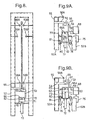
- the rear side of the rack 64 is joined to a flat metal rail 63 which, in turn, is connected to the walking beam 62 through the medium of a pair of extended transverse plates 66A, Fig. 9A, Fig. 9B and Fig. 11.
- the rack 64, and therewith also the walking beam 62 can be moved reciprocatingly in a horizontal direction with the aid of a reversible motor 75, preferably an hydraulic motor whose output shaft functions to drive a pinion wheel 68 around a vertical rotational axle.
- the pinion wheel 68 engages the teeth on the rack 64.
- the pinion wheel 68 has a width (height) such that said wheel will be in engagement with the rack 64 both in the lower position of the walking beam 62, Fig. 9A, and in the upper position thereof, Fig. 9B.
- the motor 75 is attached to a foot 52B provided in the stand 52, opposite a stand leg 52A, between the stations 9 and 10.
- the posts 53 which carry movable supports 67.
- the posts 53 extend from the respective plates 66 to an extent such as to terminate at a distance from the outer ends of the fixed supports 54, wherein the movable supports 67 extend inwardly from respective posts 53 towards, and slightly beyond the centre line of the conveyor arrangement, at a level beneath or above the fixed supports 54, depending on the positions of the movable supports 67 in the working cycle.
- Two such supports 67 are provided for each plate 4. These supports include recesses 69 for accommodating the bottom plate edges 57, in correspondence with the fixed supports 54.
- locking means are provided analogously with that described above with reference to the first conveyor arrangement.
- These locking means include lower and upper female members 76, 77, fixed on the stand 52 and provided with holes 78, 79 having vertical centre lines.
- the locking means also include vertical male members 80, 81 which are mounted on the lifting beam 71 with the aid of bracket means 82 so as to be coaxial with the holes 78, 79.
- the male members 81 are received in the upper female member 79.
- the distance or spacing between the female members 76 and 77 also determines the length of stroke of the lifting cylinders, which in the illustrated case is 110 mm, i.e. greater than the corresponding length of stroke in the first conveyor arrangement.
- the conveyor arrangements also include hydraulic equipment pressure sources, hydraulic lines, etc., and also proportional valves coacting with the horizontally acting hydraulic cylinders to dampen acceleration and retardation forces in a known manner. Also included is a microprocessor which controls the functions of all hydraulic cylinders and also the motor 75 when the motor is an hydraulic motor. Corresponding electrical control means are provided when the motor is an electric motor.
- the conveyor arrangement 25 is loaded with plate batches 4 from the electrolysis tanks with the aid of a crane.
- the plates 4 are placed in the rear section of the conveyor arrangement 24, this section being assumed to be empty.
- the spacing between the plates 4 as they are taken from the electrolysis tank is kept constant until the plates have been placed on the fixed supports 28 with the lugs 23 resting in the recesses 29.
- the walking beams 30 are in their lower, rearward positions at this point.
- Conveying of the plates 4 with the aid of the conveyor arrangement 25 is initiated by raising the lifting beams 35 to their upper positions with the aid of the lifting cylinders 37, wherewith the pins 39 slide in the U-shaped members 40 until the upper cylindrical surface of the pins 39 contacts the inner end surface of the U-shaped members 40.
- the length of stroke of the lifting cylinders 37 and the upper and lower positions of the walking beam 30 are thus determined by the length of the U-shaped members 40 and by the end stops formed by the upper rounded end of said member 40 and the respective plate 41 to which the U-shaped members 40 are attached.
- the movable supports - the plastic strips 31 - strike against the lugs 23 outside the fixed supports 28 and lift-up the plates 4 so as to move the yoke 22 out of contact with the fixed supports 28.
- the walking beams 30 are then stepped forwards by the hydraulic cylinder 47, wherewith the guide rail 32 slides on the slide rail 34.
- the step length PI coincides with the spacing between the plates 4 in the conveyor arrangement.
- the lifting beams 35, and therewith also the walking beams 30, are again lowered until the pins 39 in the U-shaped members 40 engage the plate 41.
- the plates are again seated in recesses 29 in the fixed supports 28 during this lowering movement, Fig. 6, although in new advanced positions.
- the working cycle of the first conveyor arrangement 25 is thereafter completed by returning the walking beams to their rear starting positions, said beams now being free from load.
- the plates 4 are advanced step-wise by the first conveyor arrangement 25 in this way until they reach the forward end of the conveyor path 1.
- the side support 59A prevents the thus offloaded plate 4A' from falling forwards in the receiving station 6, while the side supports 61 prevent the plate from falling backwards.
- the first-mentioned side support 59A acts directly on the plate 4A', whereas the rear side supports 61 act on the lugs 23.
- a working cycle of the second conveyor arrangement 50 will now be described. It is assumed that a plate 4A' is present in the receiving station 6 and that the offloading station 10 is empty or at least one possible plate in the offloading station has been transferred to the third conveyor arrangement 51. It is also assumed that the walking beam 62 is located in its rear position, Fig. 7. The working cycle is begun with the second lifting cylinder 72 raising the lifting beam 71 and therewith the walking beam 62 from a lower position determined by the lower female members 76, to an upper position determined by the upper female member 77. Thus, the extent of this lifting movement is defined by the distance between said members 76 and 77.
- the walking beam 62 is then advanced one step with the aid of the motor 75 through the medium of the pinion wheel 68 and rack 64, wherewith the movable supports 67 pass over the fixed supports 54, Fig. 9B.
- the step length is equal to the spacing PII between the plates along said second conveyor path 2.
- acceleration and retardation forces are dampened by proportional valves in the hydraulic lines (not shown) supplying the motor 75, which in this case is an hydraulic motor.
- Corresponding electrical control means are used when the motor is an electric motor. This essentially prevents the plates from sliding on their movable supports 54.
- the plates are able to lean against the upper side supports 59A, 59B during horizontal conveyation of the plates, while the lower side supports 58A and 58B prevent the plates 4 leaving the recesses 69. It will be understood that only the mother plates 21 are advanced further from the terminating stations 9 and 10, whereas the metal coatings 20 stripped from the plates are recovered in a manner not applicable to the present invention.
- the lifting beam 71, and therewith the walking beam 62 is lowered to its lower position determined by the lower female members 76, wherein the plates are deposited in their new positions into the recesses 56 on new fixed supports 54.
- Any plate or plates that has or have slipped in the recesses 64 despite damping of the acceleration and retardation forces with the aid of said proportional valves will be centred in the station with the aid of the end supports 74 during this lowering movement of the lifting beam.
- the fixed supports 54 and the movable supports 67 in all stations 6-10 are placed in different positions as seen in the longitudinal direction of the conveying arrangement 50 when the walking beam 62 has adopted one of its two stationary positions during the working cycle.
- the movable supports 67 are empty during the return movement and therewith pass beneath the fixed supports 54, Fig. 9A, which now support plates resting in the recesses 56.
- the horizontal frictional forces acting on the lifting beam 71 are taken-up via the bracket means 82 and the lower male members 80 and transferred to the lower female members 76 and therewith to the stand 52.
- Return of the walking beam 62 to its second position signifies completion of the working cycle of the second conveyor arrangement 50. Forward movement of the walking beam 62 during the aforedescribed working cycle results in the deposition of a plate in the outfeed station 10.
- the third conveyor arrangement 51 in the conveyor path 3 operates in a similar manner to that described with reference to the first conveyor arrangement 25 although "in reverse” and moves the plate away from the offloading station 10 during the next phase of the working cycle.
- the working cycles of the three conveyor arrangements are controlled by a microprocessor.
- Programming of the microprocessor is determined by a number of parameters, among other things by the treatment to which the plates are to be subjected in the stations 7, 8 and 9 along said second conveyor path 2.
- the microprocessor is also programmed to feed a plate 4A, 4A' into the receiving station 6 in parallel with the outfeed of a plate from the outfeed station 10.
- the microprocessor is also programmed so that a new plate 4, 4A' will not be fed into the receiving station 6 until the station is empty and another plate, more specifically a mother plate 21, has been advanced to the outfeed station 10. It will be understood that the working cycles of the three conveyor arrangements 25, 50 and 51 are synchronized with one another, although this does not mean that the individual parts of the working cycles are carried out synchronously but are rather phase displaced relative to one another.
Description
- Fig. 1
- illustrates a plant for treating mother plates that have been coated electrolytically with metal layers in an electrolysis process;
- Fig. 2
- is an enlarged view taken on the line II-II in Fig. 1 and shows the initial and terminating parts of a first conveyor path for conveying plates in their transverse direction, and shows an initial part of a second conveyor path at right angles to the first conveyor path, wherein the plates are conveyed in their longitudinal direction in said second conveyor path;
- Fig. 3
- is a view taken on the line III-III in Fig. 2;
- Fig. 4
- is a view taken along the line IV-IV in Fig. 2 and seen from above;
- Fig. 5
- is a view in still larger scale taken on the line V-V in Fig. 4;
- Fig. 6
- illustrates certain parts of the arrangement in the direction of the arrow VI in Fig. 3, in the same scale as in Fig. 5;
- Fig. 7
- is a side view taken on the line VII-VII in Fig. 1 and illustrates the first conveyor arrangement, a third conveyor arrangement and the initial and terminating parts of a second conveyor arrangement;
- Fig. 8
- is a view taken on the line VIII-VIII in Fig. 7;
- Fig. 9A and 9B
- are views taken on the line IX-IX in Fig. 7 showing the second conveyor arrangement in two different positions;
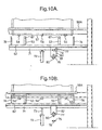
- Fig. 10A and 10B
- are views taken on the line IX-IX in Fig. 1, showing the conveyor arrangement in two different advance positions; and
- Fig. 11
- is a perspective view of part of the second conveyor arrangement with its movement devices shown in still larger scale.
Claims (10)
- An arrangement for conveying plates (4) in particular mother plates with or without a deposited metal layer, in an electrolytic metal refining plant, wherein the plates are intended to be conveyed in the conveyor arrangement (25, 50) along at least one horizontal conveyor path with the plates orientated generally vertical and equidistant from one another in the conveyor path, characterized in that the conveyor arrangement is of the walking beam kind and includes fixed supports (28, 54) and at least one walking beam (30, 62) having movable supports (31, 67), wherein the walking beam is arranged to move in a cyclic pattern, including a lifting movement in which all the plates conveyed along said path are lifted by the movable supports from their fixed supports in a first position, a forward movement in which all plates are advanced simultaneously one step while resting on their movable supports, a lowering movement in which the plates are placed on fixed supports in a new, second position, and a return movement, wherein the length of one step corresponds to the plate spacing (PI; PII) along the path.
- An arrangement according to Claim 1, characterized in that the fixed and the movable supports are located beneath projections (23) which extend laterally outwards from the plates in the plane of said plates; and in that the plates are intended to be advanced in the transverse direction thereof.
- An arrangement according to Claim 2, characterized in that the plates are intended to rest with their bottom edges on said fixed and said movable supports (54, 67) respectively; and in that the plates are intended to be advanced while resting on the movable supports (67) in the longitudinal direction.
- An arrangement according to Claim 2, characterized in that the arrangement includes two parallel walking beams (30), each having movable supports disposed beneath said projections (23), and a series of fixed supports beneath respective projections on one side of each of said walking beams.
- An arrangement according to Claim 3, characterized by a walking beam (62) having movable supports (67) beneath the plates and a series of fixed supports (54, 56) which are also located beneath the plates; and in that the movable supports are intended to pass over the fixed supports as the walking beam moves forwards and to pass beneath the fixed supports as the walking beam makes a return movement.
- An arrangement according to any one of Claims 1-5, characterized by lifting beams (35, 71) which function to lift the walking beams, lifting devices (37, 72) for lifting and lowering the lifting beams and therewith also the walking beams, means (39, 40, 76, 77, 80, 81, 82) for preventing longitudinal movement of the lifting beams, wherein the walking beams are intended to slide on the lifting beams during longitudinal movement of said walking beams.
- An arrangement according to any one of Claims 1-6, characterized by upper and lower stop means (39, 40, 41; 76, 77, 82) which define the length and terminal positions of the vertical movement of the walking beams.
- An arrangement according to Claim 4, characterized in that the movable supports on the walking beams function to hold the plates by engaging with said projections (23), preferably by virtue of projection-receiving recesses (29) provided in the supports (28).
- A plate conveyor line comprising at least two conveyor paths placed perpendicular to one another, comprising a first conveyor arrangement (25) according to any of claim 1-8 by means of which the plates are moved essentially vertically perpendicular to the plane of said plates, and a second conveyor arrangement (50) according to any of claim 1-8 by means of which the plates are moved essentially vertically to the plane of the plates, characterized in that the first conveyor arrangement (25), which includes two walking beams having supports which act against the projections on said plates, functions to deposit the plates in said second conveyor arrangement as the walking beams are lowered, with the bottom edges (57) of said plates resting on supports.
- A conveyor line according to Claim 8, which also includes a third conveyor path (3) arranged parallel with the first conveyor path (1), characterized by an offloading station in which plates are transferred from the second to the third conveyor path and in which a plate is intended to be placed on walking beams in a third conveyor arrangement (51) operating along said third conveyor path, when movable supports belonging to at least one walking beam in said second conveyor arrangement are lowered to a lower level.
Applications Claiming Priority (3)
| Application Number | Priority Date | Filing Date | Title |
|---|---|---|---|
| SE9600007A SE505735C2 (en) | 1996-01-02 | 1996-01-02 | Transport device and conveyor line for plates, especially motherboards |
| SE9600007 | 1996-01-02 | ||
| PCT/SE1997/000002 WO1997024475A1 (en) | 1996-01-02 | 1997-01-02 | A conveyor arrangement and conveyor line |
Publications (2)
| Publication Number | Publication Date |
|---|---|
| EP0871797A1 EP0871797A1 (en) | 1998-10-21 |
| EP0871797B1 true EP0871797B1 (en) | 2003-03-05 |
Family
ID=20400909
Family Applications (1)
| Application Number | Title | Priority Date | Filing Date |
|---|---|---|---|
| EP97900488A Expired - Lifetime EP0871797B1 (en) | 1996-01-02 | 1997-01-02 | A conveyor arrangement and conveyor line |
Country Status (10)
| Country | Link |
|---|---|
| US (1) | US6202830B1 (en) |
| EP (1) | EP0871797B1 (en) |
| JP (1) | JP4140663B2 (en) |
| AU (1) | AU719932B2 (en) |
| CA (1) | CA2241908C (en) |
| DE (1) | DE69719486T2 (en) |
| ES (1) | ES2193347T3 (en) |
| PE (1) | PE38298A1 (en) |
| SE (1) | SE505735C2 (en) |
| WO (1) | WO1997024475A1 (en) |
Families Citing this family (8)
| Publication number | Priority date | Publication date | Assignee | Title |
|---|---|---|---|---|
| FI107740B (en) * | 1998-09-30 | 2001-09-28 | Outokumpu Oy | Electrode transverse displacement |
| FI107941B (en) | 1999-06-10 | 2001-10-31 | Outokumpu Oy | Apparatus for transferring electrodes in electrolytic refining of metals |
| US7014036B2 (en) | 2002-11-27 | 2006-03-21 | Falconbridge Limited | Cathode linear conveyer assembly |
| JP4318727B2 (en) * | 2007-03-20 | 2009-08-26 | 日鉱金属株式会社 | Electrodeposited metal conveying device and electrodeposited metal conveying method |
| KR101237494B1 (en) * | 2011-01-20 | 2013-02-26 | 주식회사 진영이노텍 | Conveyor for transporting duplicated glasses |
| CN107364150B (en) * | 2017-09-15 | 2024-03-15 | 邵东市邵仙五金工具有限公司 | Rubber handle material arranging, conveying and heating equipment |
| CN108408422A (en) * | 2018-05-06 | 2018-08-17 | 南通南铭电子有限公司 | A kind of capacitor lead-out wire material-receiving device |
| CN113023323B (en) * | 2021-01-29 | 2023-03-03 | 广灵金隅水泥有限公司 | Material supply system |
Family Cites Families (9)
| Publication number | Priority date | Publication date | Assignee | Title |
|---|---|---|---|---|
| US1866124A (en) * | 1927-10-05 | 1932-07-05 | Siemens Ag | Conveying apparatus, particularly for electroplating |
| JPS5326902B2 (en) * | 1975-03-14 | 1978-08-04 | ||
| US4014445A (en) * | 1975-03-18 | 1977-03-29 | Mitsui Mining & Smelting Co., Ltd. | Cathode plate transfer apparatus |
| DE2644632C3 (en) * | 1976-10-02 | 1979-06-21 | C J Wennberg Ab, Karlstad (Schweden) | Method and device for the production of starting sheets for the electrolytic refining of metals |
| JPS5675323A (en) * | 1979-11-20 | 1981-06-22 | Mitsui Kinzoku Eng Kk | Method and device for piling scrap of anode plate |
| US4326937A (en) * | 1980-09-16 | 1982-04-27 | Par Systems Corp. | Grab mechanism |
| US4626159A (en) * | 1984-11-21 | 1986-12-02 | Lamb Technicon Corp. | Machine loader |
| US4669607A (en) * | 1985-08-09 | 1987-06-02 | Lamb Technicon Corp. | Workpiece transfer |
| US5012918A (en) * | 1988-12-30 | 1991-05-07 | Therma-Tron-X, Inc. | Intermittent work conveying apparatus |
-
1996
- 1996-01-02 SE SE9600007A patent/SE505735C2/en not_active IP Right Cessation
- 1996-12-30 PE PE1996000970A patent/PE38298A1/en not_active Application Discontinuation
-
1997
- 1997-01-02 JP JP52428097A patent/JP4140663B2/en not_active Expired - Fee Related
- 1997-01-02 EP EP97900488A patent/EP0871797B1/en not_active Expired - Lifetime
- 1997-01-02 CA CA002241908A patent/CA2241908C/en not_active Expired - Fee Related
- 1997-01-02 WO PCT/SE1997/000002 patent/WO1997024475A1/en active IP Right Grant
- 1997-01-02 US US09/091,811 patent/US6202830B1/en not_active Expired - Fee Related
- 1997-01-02 DE DE69719486T patent/DE69719486T2/en not_active Expired - Lifetime
- 1997-01-02 ES ES97900488T patent/ES2193347T3/en not_active Expired - Lifetime
- 1997-01-02 AU AU14049/97A patent/AU719932B2/en not_active Ceased
Also Published As
| Publication number | Publication date |
|---|---|
| SE505735C2 (en) | 1997-10-06 |
| DE69719486T2 (en) | 2003-12-24 |
| JP2000502754A (en) | 2000-03-07 |
| CA2241908A1 (en) | 1997-07-10 |
| AU1404997A (en) | 1997-07-28 |
| ES2193347T3 (en) | 2003-11-01 |
| JP4140663B2 (en) | 2008-08-27 |
| SE9600007L (en) | 1997-07-03 |
| AU719932B2 (en) | 2000-05-18 |
| PE38298A1 (en) | 1998-07-13 |
| EP0871797A1 (en) | 1998-10-21 |
| SE9600007D0 (en) | 1996-01-02 |
| CA2241908C (en) | 2005-08-23 |
| WO1997024475A1 (en) | 1997-07-10 |
| DE69719486D1 (en) | 2003-04-10 |
| US6202830B1 (en) | 2001-03-20 |
Similar Documents
| Publication | Publication Date | Title |
|---|---|---|
| EP0871797B1 (en) | A conveyor arrangement and conveyor line | |
| FI75606B (en) | RENGOERINGSFOERFARANDE OCH -ANORDNING FOER KATOD- OCH / ELLER ANODPLATTOR. | |
| CA1321565C (en) | Intermittent work conveying apparatus | |
| NL9200342A (en) | DEVICE FOR SUSPENDING POULTRY ON THE LEGS. | |
| US4268206A (en) | Article treating machine | |
| JP4602616B2 (en) | Electrode transfer device for electrolytic refining or electrowinning of metals | |
| US2738888A (en) | Processing machinery for electroplating and the like | |
| US4131531A (en) | Apparatus for stripping electrodeposited metal from cathode sheets | |
| CA1073851A (en) | Apparatus for polishing cathode plates for metal electrolytic refinery | |
| GB2104859A (en) | Method and means for the independent delivery and removal of pallets of a pallet magazine into or out of the working space of a machine tool | |
| US3088610A (en) | Skip and delayed dip mechanism for conveying apparatus | |
| JPH0346914A (en) | Automatic transfer system | |
| RU2196717C2 (en) | Device for and method of treatment of material surface by dipping | |
| CN110788508B (en) | Welding method for middle trough of coal mining machine | |
| EP1752397B1 (en) | Method and apparatus for loading work-pieces on a supporting member | |
| US3311214A (en) | Conveying machine | |
| US3770150A (en) | Work carrier lift and transfer mechanism | |
| US3013506A (en) | Skip transfer mechanism for conveying apparatus | |
| JP2528942B2 (en) | Hanger transfer mechanism for plating equipment | |
| US2869560A (en) | Processing machine | |
| US4558487A (en) | Apparatus for processing similar workpieces of varying shape, points of contour and dimension | |
| GB919357A (en) | Improvements in or relating to transfer mechanisms | |
| JPH03264699A (en) | Electric power supply controller in plating apparatus | |
| US3247948A (en) | Conveying apparatus for plating equipment | |
| CN212335348U (en) | Vertical continuous electroplating production line with automatic workpiece transfer device |
Legal Events
| Date | Code | Title | Description |
|---|---|---|---|
| PUAI | Public reference made under article 153(3) epc to a published international application that has entered the european phase |
Free format text: ORIGINAL CODE: 0009012 |
|
| 17P | Request for examination filed |
Effective date: 19980625 |
|
| AK | Designated contracting states |
Kind code of ref document: A1 Designated state(s): BE DE ES FR GB IT |
|
| GRAG | Despatch of communication of intention to grant |
Free format text: ORIGINAL CODE: EPIDOS AGRA |
|
| 17Q | First examination report despatched |
Effective date: 20020121 |
|
| GRAG | Despatch of communication of intention to grant |
Free format text: ORIGINAL CODE: EPIDOS AGRA |
|
| GRAG | Despatch of communication of intention to grant |
Free format text: ORIGINAL CODE: EPIDOS AGRA |
|
| GRAH | Despatch of communication of intention to grant a patent |
Free format text: ORIGINAL CODE: EPIDOS IGRA |
|
| GRAH | Despatch of communication of intention to grant a patent |
Free format text: ORIGINAL CODE: EPIDOS IGRA |
|
| GRAH | Despatch of communication of intention to grant a patent |
Free format text: ORIGINAL CODE: EPIDOS IGRA |
|
| GRAA | (expected) grant |
Free format text: ORIGINAL CODE: 0009210 |
|
| AK | Designated contracting states |
Designated state(s): BE DE ES FR GB IT |
|
| REG | Reference to a national code |
Ref country code: GB Ref legal event code: FG4D |
|
| REF | Corresponds to: |
Ref document number: 69719486 Country of ref document: DE Date of ref document: 20030410 Kind code of ref document: P |
|
| REG | Reference to a national code |
Ref country code: ES Ref legal event code: FG2A Ref document number: 2193347 Country of ref document: ES Kind code of ref document: T3 |
|
| ET | Fr: translation filed | ||
| PLBE | No opposition filed within time limit |
Free format text: ORIGINAL CODE: 0009261 |
|
| STAA | Information on the status of an ep patent application or granted ep patent |
Free format text: STATUS: NO OPPOSITION FILED WITHIN TIME LIMIT |
|
| 26N | No opposition filed |
Effective date: 20031208 |
|
| PG25 | Lapsed in a contracting state [announced via postgrant information from national office to epo] |
Ref country code: IT Free format text: LAPSE BECAUSE OF NON-PAYMENT OF DUE FEES Effective date: 20050102 |
|
| PGFP | Annual fee paid to national office [announced via postgrant information from national office to epo] |
Ref country code: FR Payment date: 20051208 Year of fee payment: 10 |
|
| REG | Reference to a national code |
Ref country code: FR Ref legal event code: ST Effective date: 20070930 |
|
| PG25 | Lapsed in a contracting state [announced via postgrant information from national office to epo] |
Ref country code: FR Free format text: LAPSE BECAUSE OF NON-PAYMENT OF DUE FEES Effective date: 20070131 |
|
| PGFP | Annual fee paid to national office [announced via postgrant information from national office to epo] |
Ref country code: ES Payment date: 20100125 Year of fee payment: 14 |
|
| PGFP | Annual fee paid to national office [announced via postgrant information from national office to epo] |
Ref country code: GB Payment date: 20100121 Year of fee payment: 14 Ref country code: DE Payment date: 20100121 Year of fee payment: 14 |
|
| PGFP | Annual fee paid to national office [announced via postgrant information from national office to epo] |
Ref country code: BE Payment date: 20100315 Year of fee payment: 14 |
|
| BERE | Be: lapsed |
Owner name: *OUTOKUMPU WENMEC A.B. Effective date: 20110131 |
|
| GBPC | Gb: european patent ceased through non-payment of renewal fee |
Effective date: 20110102 |
|
| PG25 | Lapsed in a contracting state [announced via postgrant information from national office to epo] |
Ref country code: BE Free format text: LAPSE BECAUSE OF NON-PAYMENT OF DUE FEES Effective date: 20110131 Ref country code: GB Free format text: LAPSE BECAUSE OF NON-PAYMENT OF DUE FEES Effective date: 20110102 |
|
| REG | Reference to a national code |
Ref country code: DE Ref legal event code: R119 Ref document number: 69719486 Country of ref document: DE Effective date: 20110802 |
|
| REG | Reference to a national code |
Ref country code: ES Ref legal event code: FD2A Effective date: 20120220 |
|
| PG25 | Lapsed in a contracting state [announced via postgrant information from national office to epo] |
Ref country code: ES Free format text: LAPSE BECAUSE OF NON-PAYMENT OF DUE FEES Effective date: 20110103 |
|
| PG25 | Lapsed in a contracting state [announced via postgrant information from national office to epo] |
Ref country code: DE Free format text: LAPSE BECAUSE OF NON-PAYMENT OF DUE FEES Effective date: 20110802 |