EP0870952B1 - Lernfähige Fuzzylogik-Drucksteuerung mit geschlossenem Regelungskreis für automatisches Getriebe - Google Patents
Lernfähige Fuzzylogik-Drucksteuerung mit geschlossenem Regelungskreis für automatisches Getriebe Download PDFInfo
- Publication number
- EP0870952B1 EP0870952B1 EP98302699A EP98302699A EP0870952B1 EP 0870952 B1 EP0870952 B1 EP 0870952B1 EP 98302699 A EP98302699 A EP 98302699A EP 98302699 A EP98302699 A EP 98302699A EP 0870952 B1 EP0870952 B1 EP 0870952B1
- Authority
- EP
- European Patent Office
- Prior art keywords
- rule
- pressure
- target
- values
- turbine speed
- Prior art date
- Legal status (The legal status is an assumption and is not a legal conclusion. Google has not performed a legal analysis and makes no representation as to the accuracy of the status listed.)
- Expired - Lifetime
Links
- 230000003044 adaptive effect Effects 0.000 title claims description 95
- 230000005540 biological transmission Effects 0.000 title claims description 42
- 230000008859 change Effects 0.000 claims description 73
- 238000000034 method Methods 0.000 claims description 60
- 238000012937 correction Methods 0.000 claims description 16
- 239000012530 fluid Substances 0.000 claims description 6
- 230000004044 response Effects 0.000 claims description 5
- 230000000694 effects Effects 0.000 claims description 3
- 230000010365 information processing Effects 0.000 claims 2
- 239000011159 matrix material Substances 0.000 description 38
- 230000008569 process Effects 0.000 description 34
- 230000006870 function Effects 0.000 description 30
- 238000004364 calculation method Methods 0.000 description 16
- 230000008878 coupling Effects 0.000 description 8
- 238000010168 coupling process Methods 0.000 description 8
- 238000005859 coupling reaction Methods 0.000 description 8
- 230000002441 reversible effect Effects 0.000 description 6
- 230000005484 gravity Effects 0.000 description 5
- 238000006243 chemical reaction Methods 0.000 description 4
- 230000009471 action Effects 0.000 description 3
- 230000007423 decrease Effects 0.000 description 3
- 238000010586 diagram Methods 0.000 description 3
- 238000011156 evaluation Methods 0.000 description 3
- 238000012546 transfer Methods 0.000 description 3
- 238000003491 array Methods 0.000 description 2
- 230000015556 catabolic process Effects 0.000 description 2
- 230000003247 decreasing effect Effects 0.000 description 2
- 230000007812 deficiency Effects 0.000 description 2
- 238000006731 degradation reaction Methods 0.000 description 2
- 238000007667 floating Methods 0.000 description 2
- 230000000670 limiting effect Effects 0.000 description 2
- 238000004519 manufacturing process Methods 0.000 description 2
- 238000013507 mapping Methods 0.000 description 2
- 230000010355 oscillation Effects 0.000 description 2
- 238000012545 processing Methods 0.000 description 2
- 238000004804 winding Methods 0.000 description 2
- 208000019300 CLIPPERS Diseases 0.000 description 1
- 230000002411 adverse Effects 0.000 description 1
- 238000013459 approach Methods 0.000 description 1
- 208000021930 chronic lymphocytic inflammation with pontine perivascular enhancement responsive to steroids Diseases 0.000 description 1
- 230000003750 conditioning effect Effects 0.000 description 1
- 238000011217 control strategy Methods 0.000 description 1
- 239000002826 coolant Substances 0.000 description 1
- 230000000994 depressogenic effect Effects 0.000 description 1
- 238000013461 design Methods 0.000 description 1
- 238000010304 firing Methods 0.000 description 1
- 230000001970 hydrokinetic effect Effects 0.000 description 1
- 230000006872 improvement Effects 0.000 description 1
- 238000012986 modification Methods 0.000 description 1
- 230000004048 modification Effects 0.000 description 1
- 238000012544 monitoring process Methods 0.000 description 1
- 230000007935 neutral effect Effects 0.000 description 1
- 230000000644 propagated effect Effects 0.000 description 1
- 230000035945 sensitivity Effects 0.000 description 1
- 230000003068 static effect Effects 0.000 description 1
- 230000002277 temperature effect Effects 0.000 description 1
Images


Classifications
-
- F—MECHANICAL ENGINEERING; LIGHTING; HEATING; WEAPONS; BLASTING
- F16—ENGINEERING ELEMENTS AND UNITS; GENERAL MEASURES FOR PRODUCING AND MAINTAINING EFFECTIVE FUNCTIONING OF MACHINES OR INSTALLATIONS; THERMAL INSULATION IN GENERAL
- F16H—GEARING
- F16H61/00—Control functions within control units of change-speed- or reversing-gearings for conveying rotary motion ; Control of exclusively fluid gearing, friction gearing, gearings with endless flexible members or other particular types of gearing
- F16H61/04—Smoothing ratio shift
- F16H61/06—Smoothing ratio shift by controlling rate of change of fluid pressure
- F16H61/061—Smoothing ratio shift by controlling rate of change of fluid pressure using electric control means
-
- B—PERFORMING OPERATIONS; TRANSPORTING
- B60—VEHICLES IN GENERAL
- B60W—CONJOINT CONTROL OF VEHICLE SUB-UNITS OF DIFFERENT TYPE OR DIFFERENT FUNCTION; CONTROL SYSTEMS SPECIALLY ADAPTED FOR HYBRID VEHICLES; ROAD VEHICLE DRIVE CONTROL SYSTEMS FOR PURPOSES NOT RELATED TO THE CONTROL OF A PARTICULAR SUB-UNIT
- B60W50/00—Details of control systems for road vehicle drive control not related to the control of a particular sub-unit, e.g. process diagnostic or vehicle driver interfaces
- B60W2050/0001—Details of the control system
- B60W2050/0043—Signal treatments, identification of variables or parameters, parameter estimation or state estimation
- B60W2050/0057—Frequency analysis, spectral techniques or transforms
-
- F—MECHANICAL ENGINEERING; LIGHTING; HEATING; WEAPONS; BLASTING
- F16—ENGINEERING ELEMENTS AND UNITS; GENERAL MEASURES FOR PRODUCING AND MAINTAINING EFFECTIVE FUNCTIONING OF MACHINES OR INSTALLATIONS; THERMAL INSULATION IN GENERAL
- F16H—GEARING
- F16H59/00—Control inputs to control units of change-speed- or reversing-gearings for conveying rotary motion
- F16H59/36—Inputs being a function of speed
- F16H59/38—Inputs being a function of speed of gearing elements
- F16H2059/385—Turbine speed
-
- F—MECHANICAL ENGINEERING; LIGHTING; HEATING; WEAPONS; BLASTING
- F16—ENGINEERING ELEMENTS AND UNITS; GENERAL MEASURES FOR PRODUCING AND MAINTAINING EFFECTIVE FUNCTIONING OF MACHINES OR INSTALLATIONS; THERMAL INSULATION IN GENERAL
- F16H—GEARING
- F16H61/00—Control functions within control units of change-speed- or reversing-gearings for conveying rotary motion ; Control of exclusively fluid gearing, friction gearing, gearings with endless flexible members or other particular types of gearing
- F16H2061/0075—Control functions within control units of change-speed- or reversing-gearings for conveying rotary motion ; Control of exclusively fluid gearing, friction gearing, gearings with endless flexible members or other particular types of gearing characterised by a particular control method
- F16H2061/0081—Fuzzy logic
-
- F—MECHANICAL ENGINEERING; LIGHTING; HEATING; WEAPONS; BLASTING
- F16—ENGINEERING ELEMENTS AND UNITS; GENERAL MEASURES FOR PRODUCING AND MAINTAINING EFFECTIVE FUNCTIONING OF MACHINES OR INSTALLATIONS; THERMAL INSULATION IN GENERAL
- F16H—GEARING
- F16H61/00—Control functions within control units of change-speed- or reversing-gearings for conveying rotary motion ; Control of exclusively fluid gearing, friction gearing, gearings with endless flexible members or other particular types of gearing
- F16H61/04—Smoothing ratio shift
- F16H2061/0477—Smoothing ratio shift by suppression of excessive engine flare or turbine racing during shift transition
-
- F—MECHANICAL ENGINEERING; LIGHTING; HEATING; WEAPONS; BLASTING
- F16—ENGINEERING ELEMENTS AND UNITS; GENERAL MEASURES FOR PRODUCING AND MAINTAINING EFFECTIVE FUNCTIONING OF MACHINES OR INSTALLATIONS; THERMAL INSULATION IN GENERAL
- F16H—GEARING
- F16H59/00—Control inputs to control units of change-speed- or reversing-gearings for conveying rotary motion
- F16H59/14—Inputs being a function of torque or torque demand
- F16H59/24—Inputs being a function of torque or torque demand dependent on the throttle opening
-
- F—MECHANICAL ENGINEERING; LIGHTING; HEATING; WEAPONS; BLASTING
- F16—ENGINEERING ELEMENTS AND UNITS; GENERAL MEASURES FOR PRODUCING AND MAINTAINING EFFECTIVE FUNCTIONING OF MACHINES OR INSTALLATIONS; THERMAL INSULATION IN GENERAL
- F16H—GEARING
- F16H59/00—Control inputs to control units of change-speed- or reversing-gearings for conveying rotary motion
- F16H59/36—Inputs being a function of speed
- F16H59/46—Inputs being a function of speed dependent on a comparison between speeds
-
- F—MECHANICAL ENGINEERING; LIGHTING; HEATING; WEAPONS; BLASTING
- F16—ENGINEERING ELEMENTS AND UNITS; GENERAL MEASURES FOR PRODUCING AND MAINTAINING EFFECTIVE FUNCTIONING OF MACHINES OR INSTALLATIONS; THERMAL INSULATION IN GENERAL
- F16H—GEARING
- F16H61/00—Control functions within control units of change-speed- or reversing-gearings for conveying rotary motion ; Control of exclusively fluid gearing, friction gearing, gearings with endless flexible members or other particular types of gearing
- F16H61/04—Smoothing ratio shift
- F16H61/08—Timing control
Definitions
- This invention relates to the field of electronic control of automatic transmissions for motor vehicles. More particularly, it pertains to adaptive control of pressure supplied to friction elements that produce gear ratio changes when engaged and disengaged.
- gear ratio changes require an element (such as a friction clutch, friction brake, brake band or one-way clutch) to disengage and another element to engage, often at approximately the same time.
- an element such as a friction clutch, friction brake, brake band or one-way clutch
- it In order for the oncoming element to engage correctly, it must have enough torque capacity to complete the shift within a specified time. If its torque capacity is too high, the shift is usually unacceptable due to its harshness. If its torque capacity is too low, engine speed will flare as the gear ratio approaches neutral during the shift, also resulting in an unacceptable shift.
- the torque capacity of a friction clutch, brake or brake band is a function of the element's characteristics and the magnitude of hydraulic pressure applied to the element.
- the magnitude of hydraulic pressure is the result of a command from a powertrain control module (PCM) to an electrohydraulic solenoid-operated valve supplied from a source of pressurised fluid.
- PCM powertrain control module
- the solenoid preferably is a variable force solenoid (VFS), which controls the magnitude to the commanded pressure.
- the pressure command to the solenoid is controlled by the strategy resident in the PCM program.
- An objective of this invention is to determine, command and apply the pressure magnitude supplied to the friction element that will produce the best shift.
- hydraulic pressure is used to control the engaged and disengaged state of the oncoming and off-going friction elements, which control the elements of the gearsets that produce gear ratio changes.
- Variation in pressure supplied to the oncoming friction element a function of the element's torque capacity, can cause variations in shift quality over the service life of the vehicle.
- the process of this invention for adapting friction element pressure is used to compensate for changes in torque capacity of the friction element.
- Friction element torque capacity is controlled by throttle valve pressure, which is calculated with reference to transmission input torque, shift inertia torque, gain and spring offsets of the clutch mathematics model, temperature compensation, and dynamic throttle adder.
- throttle valve pressure which is calculated with reference to transmission input torque, shift inertia torque, gain and spring offsets of the clutch mathematics model, temperature compensation, and dynamic throttle adder.
- open-loop pressure control provides no compensation for hardware changes, component wear and degradation, unit-to-unit variability, such as variable force transfer functions and physical tolerance variations.
- inherent conditions in a powertrain such as localised temperature effects, coefficients of friction, engine torque, and sensor drift, cannot be adequately determined and accommodated.
- a current strategy for commanding pressure at the start of a gear ratio change requires knowing inferred engine torque, inertia torque, and a calibrated offset.
- Some disadvantages of this strategy include: (1) calculated inferred engine torque may change from actual torque due to production variations, torque calculations, and engine wear over time; (2) commanded pressure may not be the same as actual pressure due to variations in the variable force solenoid; and (3) the same pressure does not always produce the same torque capacity due to component wear and variations among components.
- Adaptive controllers are designed to correct for nonlinear or time-varying changes in system parameters.
- the parameters change as the operating conditions change. This can cause problems for a controller which is tuned for only a specific condition.
- An adaptive controller can adjust to changes in system characteristics. This keeps the controller tuned throughout all the operating conditions.
- US Patent 5 665 028 discloses the features of the preamble of claim 1 or 5 and describes a system for controlling the line pressure applied to friction elements in an automatic transmission driven by an engine.
- the friction elements are engaged to produce a shift of gear ratio in the automatic transmission.
- a waveform of time variation in the engine speed is recognised.
- Waveform recognition is carried out by reference to three specific features of the waveform, namely a specified length of shift time, a specified sum of engine speed difference and an incline of engine speed difference. Fuzzy membership functions are established for the three features of the waveform and the shift capacity of the transmission is judged from the fuzzy membership functions.
- a control program executes a self-learning control of a line pressure value to rewrite the line pressure value in a hydraulic pressure table and maintain the shift capacity at an appropriate value.
- Time-varying systems also pose a problem for controllers without adaptive capabilities.
- the controller may stay tuned for a limited amount of time until the system parameters change. This can be seen in systems such as a transmission where degradation and wear start to change the system parameters after some time.
- An adaptive system can compensate for these changes in system parameters by changing the output of the systems controller.
- Adaptive capacity control can compensate for the previously discussed disadvantages by changing the commanded pressure to attain the correct friction element torque capacity over the life of the transmission.
- the method according to this invention for changing the friction element pressure uses an adaptive fuzzy logic algorithm.
- the adaptive algorithm changes a rule table stored in KAM, which produces a pressure offset for the calculated pressure for the oncoming element.
- the fuzzy logic looks for an error between desired and actual shift time. A positive error means the shift was quicker than desired, and a negative error means the shift took too long.
- the fuzzy controller changes the initial pressure based on the magnitude and sign of the error.
- the change in pressure is stored in a KAM (Keep Alive Memory) table to be used for the next shift of the same gear change.
- the fuzzy controller has four rules. First, in an upshift with a positive error, the controller decreases pressure to lengthen the time. Second, in an upshift with a negative error, the controller increases pressure to shorten the time. Third, in a downshift with a positive error, the controller increases pressure to lengthen the time. Fourth, in a downshift with a negative error, the controller decreases pressure to shorten the time.
- the present invention has achieved the following advantages in automatic transmission design and operation: (1) shift quality has been improved and maintained consistently throughout the life of the transmission; (2) effort required and length of time to calibrate parameters for an electronically controlled transmission have been decreased substantially; and (3) improved gearshift consistency has resulted in increased durability of transmission components.
- the present invention includes a self-organising fuzzy logic controller that develops an adaptive pressure adder used to modify the magnitude of pressure supplied to a friction element of an automatic transmission.
- the controller uses a turbine speed versus engine torque table in KAM to store the adaptive pressure adder for each shift.
- Tables in KAM represent fuzzy rules which are altered based on shift performance criteria to produce a self-organising fuzzy logic controller.
- the criteria which define shift performance, include the ratio change slip time and the initial ratio change time divided by the desired slip time (called target ratio).
- the slip time calculation is the time from 10% to 90% of the ratio change to within 0.5ms using interpolation methods.
- the initial ratio change time is the time from 10% to 25% of the ratio change also with an accuracy of 0.5ms.
- the desired slip time is calculated from a calibratable turbine speed versus engine torque table in read only memory.
- an adaptive pressure adjustment is determined for the next shifting event with the same conditions.
- a two-input (slip time and target ratio) fuzzy logic controller is used to calculate the pressure adjustment based on the two-shift performance measures.
- Figure 1 shows in schematic form the arrangement of gearing, clutches, and brakes for an automatic transmission to which the present invention can be applied.
- the transmission operation is described fully in U.S. Patent 4,509,389, which is assigned to the assignee of this invention.
- a torque converter 10 includes a bladed impeller that is connected to the crankshaft 12 of an engine and arranged in toroidal flow relationship with a bladed turbine, which is connected to turbine shaft 14. Also located in the toroidal flow path between the flow entrance of the turbine and the flow exit of the impeller is a bladed stator wheel, which provides a hydrokinetic torque reaction to effect torque multiplication.
- An overrunning brake supports the stator wheel and free-wheels to allow the stator to turn freely.
- the transmission includes a hydraulic pump 16, which is driven by the engine, connected directly to the engine crankshaft through a central shaft and supplies fluid to the hydraulic circuit through the valve body.
- Turbine shaft 14 drives a sprocket wheel which is connected through a drive chain or belt supported on the transmission input shaft 18.
- the gearing includes two simple planetary gear units 20, 22, each gear unit including a sun gear, a ring gear, and a set of planet pinions rotatably supported by a carrier.
- the ring gear of gear unit 20 is connected to the carrier of gear unit 22 and to output shaft 24.
- the carrier of gear unit 20 is connected to the sun gear of gear unit 22.
- the planet pinions of each of the gear units is in continual meshing engagement with the corresponding ring gear and sun gear.
- the sun gear of gear unit 22 is adapted to be held against rotation by a low intermediate brake band 26.
- a reverse brake 28 is adapted to hold the sun gear of gear unit 22 and the carrier of gear unit 20 during reverse drive.
- the sun gear of gear unit 20 is connected to a brake drum that is adapted to be held against rotation by overdrive brake 30 during overdrive operation.
- forward drive clutch 32 is engaged.
- direct drive clutch 34 is engaged.
- intermediate speed ratio clutch 36 is engaged.
- Input shaft 18 is connected to one side of the forward clutch 32, and the output side is connected to the sun gear of gear unit 20 through overrunning coupling 38.
- Input shaft 18 is connected to one side of the direct drive clutch 34, and the output side is connected to the sun gear of gear unit 20 through overrunning coupling 40.
- the chart of Figure 2 indicates the clutches and brakes that are engaged or released during operation in each of the gear ratios.
- the symbol "X” is used in the chart to designate that the clutch or brake is engaged.
- a blank in the chart indicates that the clutch or brake is released.
- a "X" symbol indicates that torque transfer is occurring between the inner and outer races
- the symbol "O/R" indicates that the overrunning coupling is free-wheeling.
- Clutch 32 is applied during operation in each of the first three driving ratios. Torque from the torque converter turbine shaft then is delivered through the chain to input shaft 18 and through the engaged clutch 32. The torque then is transferred through the overrunning coupling 38 to the sun gear of gear unit 20. Brake 26 is anchored during operation in the first two overdrive ratios and serves as a torque reaction point. Thus, torque is multiplied by the gear unit 20 and compounded with the torque multiplication of the second gear unit 22 to produce the maximum overdrive torque ratio. The output torque is delivered to the sun gear of the final drive gear unit 42, which includes a ring gear which is fixed against rotation. The output element for gear unit 42 is the planet pinion carrier, which carries pinions engaged with the sun gear and ring gear.
- That carrier drives the carrier of differential gear unit 44.
- the side bevel gears of the differential gear unit drive an axleshaft, which extends through the input shaft 18.
- Another axle halfshaft extends in the opposite direction, although it is not shown.
- Each axle halfshaft is connected to a driving wheel of the vehicle.
- Direct drive is achieved by simultaneously engaging each of the clutches 32, 34, 36. This action causes the gear elements of gear units 20 and 22 to be locked together for rotation at the same speed.
- Overdrive is obtained by disengaging clutch 32 and applying overdrive brake 30.
- the sun gear of gear unit 20 now becomes a reaction point, and the ring gear and carrier of gear unit 20 function as a driver, thereby producing an overdrive ratio.
- Gear unit 22 is inactive since all of the torque is distributed through the first gear unit 20.
- Reverse drive is achieved by disengaging clutch 36 and re-engaging clutch 32 while applying reverse brake or disc clutch 28.
- the carrier of gear unit 20 now becomes a reaction point, and the sun gear functions again as a driver. This causes the ring gear to rotate in the reverse direction and to drive output shaft 24.
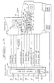
- Figure 1A illustrates the arrangement of the electronic digital control system that operates on/off shift solenoids 46, 48, 50, converter clutch on/off solenoid 54, coast clutch solenoid 56, and variable force solenoid 58, which controls the operation of line pressure in response to a pulse-width-modulated signal applied to the winding of that solenoid.
- the electronic control system includes a large scale integrated central processing unit 60; a clock pulse; interval and count-down and count-up timers; read-only memory (ROM) 62, in which programs controlling the logical operation of the CPU and data are permanently stored; read-write memory (RAM) 64; keep-alive memory (KAM) 65; input conditioning circuits 66, for converting analogue output of various sensors to digital form for processing in the CPU's; solenoid driver circuits 68 for converting digital output of the CPU to analogue voltage or current supplied to the windings of the solenoids; and data buses 69 carrying digital signals and data among the components of the control system.
- ROM read-only memory
- RAM read-write memory
- KAM keep-alive memory
- input conditioning circuits 66 for converting analogue output of various sensors to digital form for processing in the CPU's
- solenoid driver circuits 68 for converting digital output of the CPU to analogue voltage or current supplied to the windings of the solenoids
- engine speed sensor 70 which produces a square wave voltage output having a frequency proportional to the speed of the crankshaft 12
- temperature sensors 72 which sense engine coolant temperature and transmission fluid temperature by detecting an electrical resistance that varies with the temperature of the sensed medium
- manifold absolute pressure sensor 74 which produces a signal representative of static pressure in the engine intake manifold downstream of the throttle valve
- throttle position sensor 76 which produces a count representing the degree to which the engine throttle is open or the accelerator is depressed by the vehicle operator in relation to a reference position
- output shaft speed sensor 78 which produces a voltage output signal having a magnitude proportional to NO, the speed of the output shaft 24
- vehicle speed sensor 80 PRNDL sensor 82, which produces a linear voltage output whose magnitude varies with the position of the gear shift selector lever
- turbine shaft speed sensor 84 which produces a voltage or frequency proportional to the speed of turbine shaft 14.
- Signals present at the output ports of the microprocessor are carried on lines connected to the solenoids, which operate valves located in the hydraulic valve body 86.
- the hydraulic valves open and close pressure sources to control operation of the friction elements, transmission gearing and torque converter in accordance with the results produced by executing the control algorithms stored in ROM 62.
- Input signals present at the input port of the microprocessor and data stored in RAM and KAM 64 are used during that execution.
- Pulse width modulated duty cycles produced by certain driver circuits in response to microprocessor output signals resulting from execution of control algorithms are applied to solenoids 46-56.
- a variable voltage or current is applied to the variable force solenoid operated valve 58, which operates a pressure control valve 62.
- the signal applied to solenoid 60 results upon execution of a control algorithm and control method of this invention.
- the adaptive pressure magnitude output by valve 58 is directed to clutches 32, 34, 36 and brake 28. Selective engagement of these and other friction elements determine the operating gear ratio, as Figure 2 illustrates.
- the adaptive controller changes the initial magnitude of hydraulic pressure supplied to a friction element involved in a gear ratio change through use of an adaptive pressure matrix stored in Keep Alive Memory (KAM).
- KAM Keep Alive Memory
- the controller adapts the pressure based on a previous shift having the same conditions. A shift must occur under specific conditions to ensure a repeatable shift.
- the adaptive controller checks for repeatable conditions by monitoring the temperature of the transmission fluid and the change in the throttle position during a shift event. If the temperature is below a specific value, then the controller terminates the adaptive process. The adaptive process is also cancelled when a large change in throttle position is detected during the shift.
- the adaptive controller uses separate adaptive pressure matrices in KAM for each type of shift.
- Each type of shift can occur under different operating conditions including various throttle positions, engine torques, temperatures, atmospheric pressures, engine speeds, turbine speeds, and vehicle speeds. All of these conditions, especially the value of the throttle position, affect the pressure requirements for a shift event.
- An high throttle shift requires more initial shift pressure than does a closed throttle shift because engine torque input to the transmission is higher. Also, the pressure requirements at higher engine speeds may be more or less than those at lower speeds. These pressures depend on centrifugal forces in rotating clutches, turbine speed, and inertia torque resulting from a change in engine speed during a shift.
- the adaptive controller uses engine torque and turbine speed to map the shifting conditions as a speed versus load table in adaptive pressure matrices.
- the engine torque calculation is used because it takes into account both throttle position and atmospheric pressure conditions.
- the turbine-speed calculation is used because it represents when a shift would occur. With both torque and turbine speed as inputs, the speed versus load map is able to capture and differentiate between points on the transmission shift curve. This mapping provided the adaptive system with the ability to distinguish between light throttle/high speed shifts, light throttle/low speed shifts, high throttle/high speed shifts, and high throttle/low speed shifts.
- the controller includes calibratable values for scaling factors, adaptive gains, and target shift times.
- the scaling factors are set based on the ranges of the inputs to the adaptive system.
- the adaptive gains were assigned values based on sensitivity studies performed in a dynamometer. The gains were set at low values to allow the adaptive controller to reach the target shift time over a number of shifts rather than in one shift.
- Figure 4 shows the variation over time of speed ratio 84, friction element pressure 86, and output shaft torque 88 during a shift event, following the occurrence of an electronic signal representing a shift command 89 issued by the microprocessor, which results in a change of the engaged and disengaged state of an oncoming friction element and an offgoing friction element.
- 90 represents 10% of the shift completed
- 92 represents 25% of shift completion
- 94 represents 90% of shift completion.
- stage time is the duration of the period beginning with the shift command and ending at 10% shift completion 90.
- Slope time is the duration of the period between 10% and 25% shift completion, 90 and 92.
- Slip time is the duration of the period between 10% and 90% shift completion, 90 and 94.
- Figures 5-8 show for various shift events.
- the shift event results from a line pressure that is too high for the current torque level into the transmission, and results in a fast, hard shift, the duration of the gear ratio change being approximately 0.3 seconds.
- line pressure is at a desired level for the current torque resulting in desirable speed and feel for the gear ratio change, which occurs over approximately 0.5 second.
- line pressure is too low and produces a gear ratio change that is too long, extending approximately 0.7-1.0 seconds.
- target slip time which are stored permanently in ROM, are determined by a vehicle calibrator, who determines the target slip time on the basis of an acceptable feel of the shift event and its duration, and records the target slip time in matrix 98 with reference to the corresponding net torque and turbine shaft speed.
- the calibrator decides on the acceptability of the shift event upon considering whether harshness or abrupt torque changes occur, and whether the duration of the shift event will adversely affect durability of the friction elements.
- the calibrator decides subjectively on an acceptable shift slip time over the full range of net torque and turbine shaft speed.
- the period from the beginning of a shift to a predetermined percent shift completed, perhaps 50 percent, can be compared to a target period to complete the predetermined portion of a shift to create an error.
- This error is passed to a fuzzy system, from which a pressure correction can be determined for the next shift of the same type.
- Figure 9 shows representative values of target slip time accessible with reference to turbine speed and net torque as they may be stored for a 1-2 upshift in matrix 98, the wide open throttle condition being indicated at the upper right hand corner of the matrix.
- Each fuzzy logic control includes five sections: a knowledge base, scaling process, fuzzification process, inference engine, and defuzzification process.
- the knowledge base defines the scaling factors for each of two inputs and the rule consequences for a single output.
- the scaling process converts each input into a normalised value with the scaling factors in the knowledge base. These normalised values are then converted to fuzzy variables by the fuzzification process.
- the fuzzy inference engine selects the appropriate rules to fire from the knowledge base. Then these rules go through the defuzzification process to produce an output for the fuzzy system.
- the first process in the fuzzy expert system is to linearly scale the input signals 104, 106 with a range and base stored in the knowledge base for each input.
- the range is the distance between the upper and lower limits designated for the input.
- the base is the lower limit of the input signal.
- the scaling equation below results in a normalised signal norm x with a value between 0 and 1.
- norm x (x- base) range
- the midpoint or zero (if the input's lower limit is negative) of the normalised input was typically centred at a value of 0.5.
- the turbine speed signal has a minimum value of 1500 rpm and a maximum value of 6500 rpm
- the scaling factors for this signal include a range of 5,000 rpm and a base of 1,500 rpm.
- the resulting normalised signal receives the following values at various turbine speeds; 0 at 1,500 rpm, 0.5 at 4,000 rpm and 1.0 at 6,500 rpm.
- the fuzzification process produces fuzzy variables from the normalised inputs using fuzzy sets or membership functions.
- the fuzzification step uses triangular membership functions evenly spaced along the x-axis as shown in Figures 3A and 10.
- the x-axis is referred to as the universe of discourse in fuzzy logic terminology.
- the universe of discourse in this case ranges from 0 to 1. This is common to all the signals supplied as input to fuzzification steps of this invention that they have been normalised to the same 0-1 range. This allows the fuzzification routine to fuzzify any input signal without having to define a different universe of discourse for each signal.
- nmf is an integer number denoting how many regions the universe of discourse is divided into. In this case the universe of discourse is divided into six regions, giving nmf a value of six.
- norm_x is the normalised input
- fpnmf is a constant
- pnt is a pointer.
- the value of fpumf is the floating point equivalent to nmf, which is also equal to the number of membership functions minus one.
- the following equation only requires the first membership value because the two memberships functions have inverse slopes causing the memberships to add to one.
- x_mem[1] (1.0 - x_mem[0])
- Figure 10 illustrates the fuzzification process on a normalised input signal norm_x, which arbitrarily equals 0.20833 in the figure.
- the procedure starts by receiving the addresses for the normalised input signal x, pointer pnt, and first membership mem[0].
- the normalised input is then clipped to a maximum of 0.999 or a minimum of 0.0 with indirect addressing.
- the pointer pnt is calculated as an integer value.
- the membership value for mem[0] is calculated and stored.
- the address is then incremented to indirectly save the membership mem[1].
- the routine returns to the point from where it was called after the two memberships are stored. This routine is repeated for every input to the fuzzy control system. Once completed for the two inputs, the fuzzy rules can be evaluated in the inference engine.
- the antecedent memberships determined in the fuzzification process are used as inputs to a set of fuzzy if-then rules.
- the antecedent memberships are used to check the conditions necessary to fire the rules in the inference engine.
- the antecedents are typically combined using a minimum operator to form one antecedent value which determines the strength of the rule. If the strength of the rule is greater than zero, then the consequence of the rule will be executed to a certain degree.
- Each consequence in the rule is described by a linguistic term such as "add a little pressure" or "subtract a little pressure”. Fuzzy sets are used to realise these linguistic terms for each consequence.
- the membership or weighting of each consequence set is defined by the strength of the rule being fired. Typically more than one rule fires at a given time, producing a number of consequences.
- the task of the inference engine is to evaluate if-then rules based on memberships determined in the fuzzification procedure corresponding to two normalised input signals (x 1 and x 2 ).
- the inference engine uses a table to evaluate efficiently only the rules that need to be fired. This is done by indexing the table with pointers to find the desired rules.
- Each rule is in the form of an if-then statement, such as IF Antecedent1 AND Antecedent2 THEN Consequence wherein Antecedent1 is the membership of x 1 and Antecedent2 is the membership of x 2 within their respective triangular membership functions.
- the memberships for the two antecedents are represented by the symbols ⁇ Ant1 (x 1 ) and ⁇ Ant2 (x 2 ).
- the multiplication operation is used to represent the AND operation between the two antecedent membership values. The result of the multiplication determines the strength of the rule consequence IF ⁇ Ant1 (x 1 ) x ⁇ Ant2 (x 2 ) THEN Consequence
- Figure 11 shows an example of using the inference table method to determine the four rules from the inputs x 1 and x 2 .
- the rules for the two inputs include:
- the rule strength for each rule in this example is given as:
- Each rule consequence is stored in a table cell indexed with the pointers calculated in the fuzzification process for the two inputs.
- the rule consequence is determined by the value in each cell. This allows for trapezoidal membership functions by giving two adjacent cells the same consequence.
- the inference engine for this system uses an iterative routine, called as a separate procedure similar to the fuzzification routine.
- the procedure receives six values when called from the fuzzy system.
- the first value is a flag called ADAPT FLAG, which allows the rule consequences and strengths to be saved for the adaptive process.
- the second value is the pointer (XPNT) for the x-axis fuzzy input.
- the third value is the address of the first membership for the x-axis input called MEMX.
- the fourth and fifth values are similar to the first and second inputs, but they are used for the y-axis fuzzy input to the inference engine.
- the last value passed to the routine is the address of the matrix in the knowledge base containing the consequences for the if-then rules, such as matrices 89, 108, 140.
- the Rulestrength routine iterates four times with the use of two counters (i and j).
- the third counter k is used to index through the four rules so that they are saved for the adaptive process.
- the routine first indexes through the consequence table to store the selected consequences to a variable called FIRE_RULE. Then the routine calculates the rule strength by multiplying the two antecedent membership values and storing the result into RULE_ST. If ADAPT_FLAG was set, the FIRE_RULE and RULE_ST values are stored in two arrays (ADAPT_RULE[] and ADAPT_STRENGTH[]) indexed by the counter k.
- the next process in the routine executed part of the defuzzification process by calculating the values FUZ_NUM and FUZ_DEN.
- the defuzzification process in this application uses a centre of gravity routine to evaluate the overall output from the four rules fired in the inference engine.
- Each rule output is considered a fuzzy triangular membership function with the height determined by the rule strength and the centre at the value of the consequence, as shown in Figure 12.
- the centre of gravity is calculated by taking the average of the four consequences weighted by the rule strength.
- the first half of the centre of gravity calculation is executed in the Rulestrength routine.
- the FUZ NUM variable equals the summation of the rule consequences weighted by the rule strengths; the FUZ_DEN variable equals the summation of the rule strengths.
- the centre of gravity y is then calculated by dividing these two variables as shown in the following equation
- This final calculation is performed outside of the Rulestrength routine to allow for more rules to be added to the centre of gravity calculation. This enabled the fuzzy system to fire more rules by executing the Rulestrength procedure again with another rule base.
- the signals tq_net 104 and NT 106 representing the magnitude of net inferred engine torque and turbine speed, respectively, are used with scaling functions 105, 107, respectively, to produce corresponding normalised variables norm_tq and norm_nt, which are used as input to fuzzy sets or membership functions 112, 114.
- the sets are non-crisp functions, described in linguistic terms and have specific shapes. Sets in conventional logic differ from fuzzy sets in that conventional sets are crisp rather than shaped. Crisp sets only allow an input to either belong or not belong to a set rather than to have an intermediate degree of membership. Fuzzy sets allow for this intermediate membership with a value between 0, representing full membership, and 1, representing no membership, depending on the shape of the set. Membership is determined by the location at which the input falls in the set.
- the initial pressure adjustment (adapt_poff) is determined in the first fuzzy system.
- the inputs to this system are turbine speed and inferred engine torque.
- the knowledge base of rule consequences for this system are stored in a KAM table for each shift.
- This table (Adaptive Pressure Matrix 108) contains consequence values in units of pressure (in increments of 1 psi). These rule consequences are initialised to zero at the start the adaptive process, then the values are modified by the adaptive routine to correct for errors in slip time.
- the knowledge base in the system contains scaling factors 105, 107 to produce fuzzy membership sets for turbine speed and engine torque inputs. Also included in the knowledge base are the rule consequences to produce the adapt-poff pressure adjustment.
- the rule consequence membership sets represented by triangular functions are centred at the values stored in the rule table and can range preferably from -127 psi to +127 psi (-875 kPA to + 875 kPA). With these consequence memberships and the two input memberships, rules of the following form are created in the fuzzy system: IF (nt is FAST) AND (torque-net is HIGH) THEN (ADD A SMALL AMOUNT OF PRESSURE)
- the memberships for the two antecedents and the consequence can vary depending on the inputs and the values in adaptive pressure matrix 108.
- the process for determining adapt-poff first normalises engine torque and turbine speed inputs, producing norm_nt and norm_tq. Additionally, the first step initialises two pointers (pnt_pam and pnt_target) to the addresses of matrix 108 and a target slip time matrix 98. Then the normalised values are fuzzified to produce two sets of memberships (tq_mem[] and nt_mem[]) which are passed to the Rulestrength procedure. The Rulestrength procedure is called. With the adapt_flag set, the rule consequences and strengths are stored in the adapt_rule[] and adapt_strength[] arrays.
- inferred engine torque (inf_ torque ) input equals 41 ft•lbs (56N.m) at the start of a shift.
- the normalised turbine speed equals 0.8833 when scaled with a range of 4500 rpm and a base of 1500 rpm.
- the normalised torque equals 0.2333 when scaled with a range of 90 ft-lbs (122 Nm) and a base of 20 ft-lbs. (27 Nm).
- the four rules are then evaluated in the inference engine by multiplying the memberships together, finding the rule strengths for each rule.
- the four rule strengths are associated to each rule consequence as follows:
- This pressure is then added to the initial shift pressure calculation as an adaptive correction.
- the controller calculates the target speed ratio, and stores the throttle position and start time before determining the initial shift pressure.
- the target speed ratios, clutch gain factors, and shift inertia's are determined separately for each shift. Thereafter, the expected change in speed ratio is calculated. Then a start of shift time (shift_start) i s captured from a one millisecond counter. Additionally, the throttle position at the start of the shift is also captured at the same time. Finally, the initial friction element pressure is calculated as a function of the shift inertia, inferred engine torque, and adaptive adjustment adapt_poff.
- the control calculates percent shift complete, i.e., how much of the shift is complete.
- the adaptive strategy captures the time when the shift percent passes 10, 25, 90 and any other relevant shift complete. Preferably the process for capturing the time is done every sixteen milliseconds starting with the speed ratio calculation.
- the speed ratio is calculated by dividing turbine speed (NT) by output shaft speed (NO). This value is then used to calculate shift_percent, slip_time, slopel_time, stage_time, and any other relevant time. Additionally, the throttle position is also captured at this time. Once these values are captured, a slip_time_target is calculated for comparison to actual slip_time.
- a second fuzzy controller determines the desired slip_time_target. This fuzzy system receives the same turbine speed and inferred torque inputs as the first fuzzy system that produced adapt_poff. This eliminates the need to re-scale and fuzzify the inputs because the memberships are already calculated.
- the knowledge base of rule consequences for this fuzzy system is stored in calibratable ROM table called the Target Slip Matrix 98.
- the desired time for a shift at a specific condition of speed versus load was determined by calibration as described above and stored in Matrix 98 for each gear ratio change.
- the time values are preferably stored in increments of sixteen milliseconds, allowing the target slip times to fit into a single byte of memory. This allows the consequences to range from 0 ms to 4096 ms with a resolution of sixteen milliseconds.
- the target slip times are converted to values of milliseconds by a defuzzification process, resulting in a target time value called slip_time_target.
- the code for the target time evaluation is executed at the end of each shift along with calculating the absolute change in throttle position during the shift event.
- the calls to the fuzzy logic routines are similar to those in the first fuzzy system except that the adapt_flag was not set in this case.
- This target time value is then used to determine an error calculation (target-error) 136 in a third fuzzy system designed to adapt the initial shift pressure.
- LP learned LP + adapt_poff + rom_poff
- LP learned is the line pressure applied to the friction element in accordance with this invention
- LP is the line pressure magnitude produced by a source of line pressure 124 before its magnitude is adapted in accordance with this invention
- adapt_poff is the output of the second fuzzy system
- rom_poff is the output of defuzzification 118 that follows the rule evaluation of adaptive pressure matrix 110 stored in ROM after the immediately preceding shift of the same type as the shift being adapted.
- Adapt_poff and rom_poff are combined at summing junction 120, and their sum is added at summing junction 122 to the magnitude of pressure, 50-70 psi (350-480 kPA), produced by a source of lined pressure 124 operating under conventional control.
- a VFS transfer function 126 relates pressure output from summing junction 122 and the corresponding magnitude of electric current supplied to variable force solenoid 58, which supplies pressure at the adapted magnitude to a friction element that is engaged to produce the shift.
- the percent shift completion is calculated continually during the shift event, and from its magnitude slip_time, slope1_time, and stage_time are determined as described above.
- Slip_time_target 132 determined from the second fuzzy system with reference to turbine speed membership and torque membership, is connected to summing junction 134, where slip time is subtracted to produce target error 136, one input to a third fuzzy system at fuzzification process step 138.
- Slope1_time 142 is divided by Slip_time_target 132 to produce target_ratio 144, which is used as another input to a third fuzzy system at fuzzification process step 146.
- a negative value of target_error represents a shift that is too long; a positive value indicates a shift that is too short.
- the input shift time error can be calculated by taking the difference between target shift time and the corresponding actual shift time, such as the time to complete 50% of the shift.
- the actual shift time is calculated by subtracting the time captured at the start of the shift from the time at 50% shift complete
- the two inputs to the third fuzzy system indicate conditions for adapting pressure.
- the membership functions for this input are preferably represented by triangular membership functions, such as those of Figures 18 and 19.
- the third fuzzy system resolves the pressure adjustment required in the Adaptive Pressure Matrix 108 with a knowledge base of rule consequences.
- the rule base for this system was realised in a calibratable table Adaptive Strength Matrix 140 located in ROM, as shown in Figure 3C.
- the calibration values for the rule consequence matrix are in units of 1 psi pressure increments.
- the rules are applied to increase pressure when a shift is too long, decrease pressure when a shift is too short, and not change pressure around the desired shift times to incorporate a dead band. These rules produce a desired pressure for adjusting the Adaptive Pressure Matrix 108 called adapt_press 174.
- the adapt_press value 174 is then passed to the Adapt_Tables routine to modify the initial shift pressure for the next shift.
- Figure 13 shows on its vertical scale the change in duration of slip time 150, stage time 152 and target ratio 154 that result from a change in magnitude of pressure applied to a friction element to produce a shift event with reference to a base friction element pressure, the vertical axis 156.
- slip time and the duration of the gear ratio change are too short; therefore, clutch pressure should be decreased.
- target slip time and the duration of the gear ratio change are acceptable; therefore, the friction element pressure should be maintained at its current level.
- stage time is too long and the gear ratio change is too long; therefore, to correct these conditions to a more acceptable shift event, clutch pressure should be increased by a large amount.
- the target ratio is too high and the gear ratio change too long; therefore, to correct these conditions, clutch pressure should be increased by a medium amount.
- the adaptive strength matrix 140 shown in Figure 14 is populated with adaptive pressure values that would correct the problems discussed with reference to the zones of Figures 14 and produce an acceptable gear ratio change.
- slip time error varies in degree from large negative LN, medium negative MN, small negative SN, zero Z, small positive SP, medium positive MP, and large positive LP.
- the target ratio error varies in degree from zero Z, small S, medium small MS, medium M, medium large ML, large L, and very large VL.
- the upper right hand corner of matrix 140 contains adaptive pressure values that would suitably correct for the short slip times described with reference to zone 158.
- the upper portion of the middle column of matrix 140 contains adaptive pressure values that correspond to the acceptable gear ratio change represented by zone 160.
- the magnitudes of adaptive pressure located at the left hand central area of matrix 140 would correct with the deficiencies represented in zone 162.
- the lower rows extending across the width of matrix 140 contained adaptive pressure magnitudes that would correct for the deficiencies described above with reference to zone 164.
- Figure 18 shows slip time error in seconds extending between -0.4 and 0.4 seconds, that range varying between large negative slip time error and large positive slip time error.
- Figure 18 shows the fuzzy sets employed during process step 138.
- Figure 19 shows target ratio extending over a normalised range between 0.0 and 1.0, each of the triangular fuzzy sets are arranged between very small and very large.
- the fuzzy sets of Figure 19 are identical to those of process step 146.
- adapt_press is the weighted average of the four Rule consequences.
- Stage time determined at step 128, is used as input to a calibrated function 175 relating stage_time and a pressure adder.
- Function 175 produces as output the variable stage_adder, which is added to adapt_press at summing junction 176.
- Each type of shift can occur with different conditions including various throttle positions, engine torques, temperatures, atmospheric pressures, engine speeds, turbine speeds, and vehicle speeds. All of these conditions affect the pressure requirements for a shifting event, especially the value of the throttle position.
- a higher throttle shift requires more initial shift pressure than does a lower throttle shift because engine torque into the transmission is higher.
- the pressure requirements at higher engine speeds may be more or less than those at lower speeds.
- the adaptive controller uses engine torque and turbine speed to map the shifting conditions as a speed versus load table in the Adaptive Pressure Matrix 108.
- the engine torque calculation is used because it takes into account both throttle position and atmospheric pressure conditions.
- the turbine-speed calculation is used because it represents the occurrence of a shift. With both torque and turbine speed as inputs, the speed versus load map is able to capture and differentiate between points on the transmission shift curve, Figure 2. This mapping provides the adaptive system with the ability to distinguish between light throttle/high speed shifts, light throttle/low speed shifts, high throttle/high speed shifts, and high throttle/low speed shifts.
- function 180 which relates a throttle position change, tp_change, and a variable tp_adjust, which is carried to junction 182.
- the purpose of function 180 is to reduce the amount of adaptive pressure adjustment that occurs if a change in throttle position occurs during the gear ratio change.
- the variable tp_change is the absolute value of the number of counts corresponding to the current throttle position at the beginning of the gear ratio change minus the number of counts at the end of the gear ratio change.
- the process for calculating the adaptive pressure change includes six steps.
- variable STR_GAIN 190 in the equation is an overall adaptive gain and a propagated gain at higher values.
- the gain is set higher than unity, the adaptive pressure adjustment across the four cells is larger than the value of ADAPT_PRESS. If the gain is less than unity, then the pressure adjustment is less than ADAPT_PRESS.
- a gain of zero prevents all the cells in the matrix 108 from being modified.
- gain 190 is about 2.0.
- TERM_ADJ i typically less than unity, each cell is only modified by a fraction of ADAPT_PRESS.
- TERM_ADJ could be calculated as an integer or a floating point number depending upon the form in which the rule consequences are stored in the matrix 108. In this case, TERM_ADJ is calculated as an integer.
- a new rule consequence is created in the fourth step 196 by adding the adaptive adjustment value to the cells that require modification.
- a NEW_RULE variable is calculated with the addition of TERM_ADJ to the consequences of the four rules stored in ADAPT_RULE[].
- the consequences NEW_RULE ADAPT_RULE[k] + TERM_ADJ are stored in ADAPT_RULE[].
- the process of limiting the new rule consequences 198 to a calibratable value is performed in the fifth step.
- the value in NEW_RULE is clipped to a minimum value (MIN_RULE) and a maximum value (MAX_RULE), which are constraints due to the system being controlled.
- a final step in the adaptive routine stores the new rule consequence values in the knowledge base, for example, in the highlighted cells of Matrix 108. This was accomplished by replacing the previous rule consequences in matrix 108 with the new rule consequences 198. After the routine executes the four rules, the routine returns to the strategy with the adaptive process completed.
- the following example describes the adaptive process from calculating the target_error 136 and determining adapt_press in the third fuzzy system to modifying adaptive pressure matrix 108.
- the rules in this third fuzzy controller include: 1) If (slip time is very short) And (target ratio is small) Then (subtract a very large amount of pressure); 2) If (slip time is short) And (target ratio is small) Then (subtract a large amount of pressure); 3) If (slip time is long) And (target ratio is small) Then (subtract a small amount of pressure); 4) If (slip time is very long) And (target ratio is small) Then (add a medium amount of pressure); 5) If (slip time is very short) And (target ratio is medium) Then (subtract a large amount of pressure); 6) If (slip time is short) And (target ratio is medium) Then (subtract a small amount of pressure); 7) If (slip time is long) And (target ratio is medium) Then (add a small amount of pressure); 8) If (slip time is very long) And (target ratio is medium) Then (add a large amount of pressure); 9) If (slip time is
- the rules indicate that when the target ratio is small, the open-loop pressure calculation is above the desired level, causing an abrupt shift.
- the target ratio value is medium, the slip time is used as the criteria for whether the shift was desirable.
- a large target ratio value indicates the open-loop pressure was low enough to cause a slip-bump in a shift with accumulators.
- the adaptive pressure adjustment from the fuzzy controller is then increased if the stage time (time from solenoids switch to 10% to ratio change) is greater than a calibratable value.
- the adaptive pressure is also multiplied by a factor determined from the deviation in the throttle position reading for the shift event. Once the adaptive pressure is calculated, the adjustment is added to the KAM table for the turbine speed versus engine torque conditions.
- target_error is Negative Large(0.5) AND Negative Medium (0.5) target_ratio is Low (0.6) AND Medium Low (0.4)
- the adapt_press value 174 then enters the Adapt_Table routine along with the values stored in adapt_strength[] 188 and adapt_rule[] 194 from the first fuzzy system, from which adapt_poff is determined.
- adapt_strength[] 188 and adapt_rule[] 194 from the rules fired in the first fuzzy system example include:
- the rule strengths 188 are multiplied by adaptive gain str_gain 190, which equals 2.7 for this example.
- the results from the multiplication are then limited at 192 to a maximum value of unity.
- the following four results 196 for the new rule strengths are:
- the resulting new consequence values 198 include:
- This action completes the adaptive process for adjusting the friction element pressure before the next gear ratio change of the same type, such as a 1-2 upshift.
- the procedure is repeated for each subsequent gear ratio change and for each shift of a different type, such as upshifts (1-2, 2-3, 3-4), three downshifts (2-1, 3-2, 4-3), and four skip shifts (1-3, 2-4, 4-2, 3-1).
- a desired response for the adaptive system is to adapt slowly the initial shift pressure to produce a desired shift time over a number of shifts. Additionally, once the desired shift time is achieved, the controller should maintain that shift time with no oscillation in the pressure adjustments.
- the response and stability of the adaptive system is dictated by the resolution of the speed versus load rule table, the rules for adapting the pressure, and the adaptive gain.
- the speed versus load table determined the difference between shifting conditions. If the table is too small, then the conditions for a light throttle and a heavy throttle shift will mutually overlap. This causes oscillation in the pressure adjustment because a single condition in the table actually represents two different shifting conditions. If the table is too large, then too many possible shifting conditions will exist to make the system responsive.
- the rules for adapting the pressure require a dead band when the target shift time is achieved. When the adaptive controller does not attain the target times, the rules correct the pressure in proportion to the shift time error.
- an adaptive gain is set at a value where the adaptive pressure adjustment occurs over a number of shifts, preventing the system from oscillating.
- a number of criteria are used to determine whether to adapt a shift using the method of this invention. These criteria include: 1) the throttle position at the start of the shifting event does not deviate from the throttle at the end of the shift event by a calibratable amount; 2) power-on upshifts are only adapted while both power-on and coast downshifts are adapted; 3) a shift must occur a calibratable amount of time after a previous shift in order to adapt the shift; 4) a shift must occur a calibratable amount of time after a shift was commanded so that change-of-mind shifts are not adapted; the transmission fluid temperature must be above a calibrated temperature to allow shifts to be adapted. With these criteria met, only shifts with stable and repeatable torque, speed, and temperature conditions are adapted.
Landscapes
- Engineering & Computer Science (AREA)
- General Engineering & Computer Science (AREA)
- Physics & Mathematics (AREA)
- Fluid Mechanics (AREA)
- Mechanical Engineering (AREA)
- Control Of Transmission Device (AREA)
Claims (8)
- Ein Verfahren zur Änderung des durch eine Druckquelle (62) erzeugten und zu einem Reibungselement (32) gelieferten Drucks, um dieses zur Erzeugung eines Übersetzungsverhältnis-Wechsels in einem - zur Verwendung mit einem Motor und einer Drehmoment-Wandlerturbine angepaßten - automatischen Getriebe einzurücken, das die Schritte umfaßt:dadurch gekennzeichnet daß:Bestimmen der gegenwärtigen Turbinendrehzahl und des gegenwärtigen Motordrehmoments zu Beginn eines Übersetzungsverhältnis-Wechsels, und Flankenzeit und Schlupfzeit während des Übersetzungsverhältnis-Wechsels;Bestimmen einer anfänglichen, adaptiven Druckanpassung, die der gegenwärtigen Turbinendrehzahl und dem gegenwärtigen Motordrehmoment entspricht, durch Verwendung eines ersten Fuzzy-Logic-Systems (105, 107, 112, 114, 108, 110, 116, 118), das auf Turbinendrehzahl und Motordrehmoment bezogene, adaptive Druckanpassungs-Werte aufweist;Erzeugen eines Übersetzungsverhältnis-Wechsels durch Druckbeaufschlagung des Reibungselementes (32) von der Druckquelle (62) bei dem aus der Verwendung dieser anfänglichen Druckanpassung resultierenden Druck;die Bestimmung eines - der gegenwärtigen Turbinendrehzahl und dem gegenwärtigen Motor-Zielwert entsprechenden- Schlupfzeit-Zielwertes durch ein zweites Fuzzy Logic-System (105, 107, 112, 114, 98, 130) erfolgt, das auf Turbinendrehzahl und Motordrehmoment bezogene, annehmbareSchlupfzeit-Zielwerte aufweist;man einen Zielfehler als den Unterschied zwischen dem Schlupfzeit-Ziel und der Schlupfzeit bestimmt;man ein Zielverhältnis der Flankenzeit und des Schlupfzeit-Ziels erzeugt;die Bestimmung einer - dem Zielfehler und dem Zielverhältnis entsprechenden-Druckkorrektur durch ein drittes Fuzzy Logic-System (138, 140, 1146, 178) erfolgt, das auf Zielfehler und Zielverhältnis bezogene, adaptive Druckwerte aufweist;man unter Verwendung dieser Druckkorrektur und adaptiver Druckanpassungs-Werte korrigierte Druckanpassungs-Werte erzeugt, die gegenwärtiger Turbinendrehzahl und gegenwärtigem Motordrehmoment entsprechen;man diese adaptiven Druckanpassungs-Werte des ersten Fuzzy-Logic-Systems (105, 107, 112, 114, 108, 110, 116,118), die dem gegenwärtigen Motordrehmoment und der gegenwärtigen Turbinendrehzahl entsprechen, durch die korrigierten, adaptiven Druckanpassungs-Werte ersetzt; und daßman einen zweiten Übersetzungsverhältnis-Wechsel durch Druckbeaufschlagung des Reibungselements (32) von der Druckquelle (62) mit dem Druck erzeugt, der durch Verwendung des ersten Fuzzy-Logic-Systems (105, 107, 112, 114, 108, 110, 116, 118) resultiert, das diese korrigierten, adaptiven Druckanpassungswerte aufweist.
- Ein Verfahren gemäß Anspruch 1, das weiterhin umfaßt:Bestimmen der Stufenzeit während des Übersetzungsverhältnis-Wechsels;Erzeugen eines Stufenaddierers, der groß ist wenn die Stufenzeit lang ist, und der relativ gesehen kleiner ist wenn die Stufenzeit relativ gesehen kleiner ist;Addieren des Stufenaddierers zu der Druckkorrektur;Erzeugen korrigierter - der gegenwärtigen Turbinendrehzahl und dem gegenwärtigen Motordrehmoment entsprechenden - Druckanpassungs-Werte unter Verwendung dieser anfänglichen Druckanpassungs-Werte und der Summe dieser Druckkorrektur und des Stufenaddierers; undErsetzen dieser anfänglichen Druckanpassungs-Werte durch diese korrigierten, adaptiven Druckanpassungs-Werte.
- Ein Verfahren gemäß Anspruch 2, das weiterhin umfaßt:Bestimmen der Änderung in der Drosselklappenstellung während des Übersetzungsverhältnis-Wechsels;Erzeugen eines Drosselklappenstellungs-Anpassungsfaktors, der den Effekt der Druckkorrektur vermindert, wenn die Änderung in der Drosselklappenstellung groß ist;Addieren des Stufenaddierers zu der Druckkorrektur;Erzeugen eines Produktes durch Multiplizieren der Summe des Stufenaddierers und dieser Druckkorrektur;Erzeugen korrigierter, adaptiver - der gegenwärtigen Turbinendrehzahl und dem gegenwärtigen Motordrehmoment entsprechender- Druckanpassungswerte unter Verwendung dieses Produktes; undErsetzen dieser anfänglichen Druckanpassungs-Werte durch entsprechend korrigierte, adaptive Druckanpassungs-Werte.
- Ein Verfahren gemäß einem der Ansprüche 1 bis 3, in dem der Schritt der Bestimmung einer anfänglichen Druckanpassung durch Verwendung des ersten Fuzzy-Logic-Systems (105, 107, 112, 114, 108, 110, 116, 118) es umfaßt aus dem ersten Fuzzy-Logic-System die - dem gegenwärtigen Motordrehmoment und der gegenwärtigen Turbinendrehzahl entsprechenden - Regelstärken und Regelfolgen zu bestimmen, wobei das Verfahren weiter umfaßt:Kappen dieser Regelstärken auf einen vorherbestimmten, maximalen Grenzwert;Erzeugen eines Produktes durch das Multiplizieren der Regelstärken mit dieser Druckkorrektur;Erzeugen korrigierter Regelfolgen durch hinzuaddieren dieses Produktes dieser Regelstärke und dieser Druckkorrektur zu diesen Regelfolgen;Ersetzen dieser Regelfolgen durch die entsprechenden korrigierten Regelfolgen; undErzeugen eines zweiten Übersetzungsverhältnis-Wechsels durch Druckbeaufschlagung des Reibungselements (32) von der Druckquelle (62) mit dem Druck, der durch Verwendung des ersten Fuzzy-Logic-Systems resultiert, das diese korrigierten Regelfolgen aufweist.
- Ein System zur Adaptierung des Drucks zur Erzeugung eines Übersetzungsverhältnis-Wechsels in einem automatischen Getriebe, das eine Drehmomentwandler-Turbine besitzt und für die Verwendung mit einem eine Drosselklappe aufweisenden Motor angepaßt ist; wobei das Getriebe ein Reibungselement (32) einschließt, das eingerückt ist um einen Übersetzungsverhältnis-Wechsel zu erzeugen; und eine schaltmagnetbetätigte Druckquelle (62), um Fluid mit einem Druck zu diesem Reibungselement (32) zu liefern, der sich in Reaktion auf ein von einem Computer (60) erzeugtes Signal hin ändert; wobei das System umfaßt:dadurch gekennzeichnet, daß:einen Drosselklappen-Stellungssensor (76), der ein die Stellung der Motor-Drosselklappe darstellendes Signal erzeugt; undeinen Turbinendrehzahl-Sensor (84), der ein die Turbinendrehzahl darstellendes Signal erzeugt; wobeider Computer (60) Eingabe-Schnittstellen aufweist, die angepaßt sind um das durch den Turbinendrehzahl-Sensor (84) und den Drosselklappen-Stellungssensor (76) erzeugte Signal zu empfangen; und bei Beginn jedes Übersetzungsverhältnis-Wechsels ein Zeitgeber ausgelöst wird, um mit Hilfe des Computers Flankenzeit und Schlupfzeit während eines Übersetzungsverhältnis-Wechsels zu bestimmen;der Computer (60)mit elektronischem Speicher (62, 64, 65) bereitgestellt wird, der Information verarbeitende Anweisungen enthält, die einschließen:ein erstes Fuzzy-Logic-System (108, 110, 112, 114, 116, 118), das auf Turbinendrehzahl und Motordrehmoment bezogene, adaptive Druckanpassungs-Werte aufweist, um eine anfängliche, der gegenwärtigen Turbinendrehzahl und dem gegenwärtigen Motordrehmoment entsprechende Druckanpassung zu bestimmen;wobei der Computer (60) mit Anweisungen zur Erzeugung korrigierter Druckanpassungs-Werte bereitgestellt ist, die der gegenwärtigen Turbinendrehzahl und dem gegenwärtigen Motordrehmoment unter Verwendung dieser Druckkorrektur und dieser adaptiven Druckanpassungs-Werte entsprechen;der computerelektronische Speicher (62, 64, 65) Informationen verarbeitende Anweisungen enthält, die einschließen:ein zweites Fuzzy-Logic-System (98, 112, 114, 130), das auf Turbinendrehzahl undMotordrehmoment bezogene Schlupfzeit-Zielwerte aufweist, um ein der gegenwärtigen Motordrehzahl und dem gegenwärtigen Motorziel entsprechendes Schlupfzeit-Ziel zu bestimmen; undein drittes Fuzzy-Logic-System (138, 140, 146, 178), das auf den Zielfehler -den Unterschied zwischen dem Schlupfzeit-Ziel und der Schlupfzeit - und Zielverhältnis - ein Verhältnis der Flankenzeit und des Schlupfzeit-Ziels - bezogene, adaptive Druckwerte aufweist, um eine dem Zielfehler und Zielverhältnis entsprechende Druck-Korrektur zu bestimmen;
und wobei man diese - dem gegenwärtigen Motordrehmoment und der gegenwärtigen Turbinendrehzahl entsprechenden - adaptiven Druckanpassungs-Werte des ersten Fuzzy-Logic-Systems (108, 110, 112, 114, 116, 118) durch die korrigierten, adaptiven Druckanpassungs-Werte ersetzt. - Ein System gemäß Anspruch 5, in dem das erste Fuzzy-Logic-System (105, 107, 108, 110, 112, 114, 116, 118) einschließt:einen Normierungs-Prozessor (105, 107), um normierte Werte innerhalb entsprechender Bereiche und Basiswerte für das Signal zu erzeugen, das durch den - die Stellung der Motor-Drosselklappe darstellenden - Drosselklappen-Stellungssensor (76) erzeugt wird; und für das durch den - die Turbinendrehzahl darstellenden - Turbinendrehzahl-Sensor (84) erzeugte Signal;einen Entschärfungs-Prozessor (112, 114), der unscharfe Sätze zur Bestimmung von Zugehörigkeitswerten aufweist, die jedem dieser normierten Werte entsprechen;eine Wissensbasis (108, 110) von im Speicher als Tabellen abgelegten Druckanpassungs-Regelfolgen, die jeder Art von Übersetzungsverhältnis-Wechsel entsprechen und nach diesen Zugehörigkeitswerten indiziert sind;einen Schlußfolgerungsmechanismus, um aus diesen Tabellen die relevanten Regelfolgen und die Regelstärken zu bestimmen, welche diesen Zugehörigkeitswerten entsprechen; undeinen Schärfungs-Prozessor (116, 118) zur Bestimmung einer Ausgabe-Druckanpassung aus einem gewichteten Durchschnitt dieser Regelfolgen und Regelstärken.
- Ein System gemäß Anspruch 5 oder 6, in dem das zweite Fuzzy-Logic-System einschließt:einen Normierungs-Prozessor (112, 114), um normierte Werte innerhalb entsprechender Bereiche und Basiswerte für das Signal zu erzeugen, das durch den - die Stellung der Motor-Drosselklappe darstellenden - Drosselklappen-Stellungssensor (76) erzeugt wird; und für das durch den - die Turbinendrehzahl darstellenden - Turbinendrehzahl-Sensor (84) erzeugte Signal;einen Entschärfungs-Prozessor (112, 114), der unscharfe Sätze zur Bestimmung von Zugehörigkeitswerten aufweist, die jedem dieser normierten Werte entsprechen;eine Wissensbasis (98) von im Speicher als Tabellen abgelegten Schlupfzeit-Ziel-Regelfolgen, die jeder Art von Übersetzungsverhältnis-Wechsel entsprechen und nach diesen Zugehörigkeitswerten indiziert sind;einen Schlußfolgerungsmechanismus, um aus diesen Tabellen die relevanten Regelfolgen und die Regelstärken zu bestimmen, welche diesen Zugehörigkeitswerten entsprechen; undeinen Schärfungs-Prozessor (130) zur Bestimmung eines Ausgabe-Schlupfzeit-Ziels aus einem gewichteten Durchschnitt dieser Regelfolgen und Regelstärken.
- Ein System gemäß den Ansprüchen 5, 6 oder 7, in dem das drittr Fuzzy-Logic-System einschließt:einen Entschärfungs-Prozessor (138, 146), der unscharfe Sätze zur Bestimmung von Zugehörigkeitswerten aufweist, die diesem Zielfehler und diesem Zielverhältnis entsprechen;eine Wissensbasis (140) von im Speicher als Tabellen abgelegten Druckkorrektur-Regelfolgen, die jeder Art von Übersetzungsverhältnis-Wechsel entsprechen und nach diesen Zugehörigkeitswerten indiziert sind;einen Schlußfolgerungsmechanismus, um aus diesen Tabellen die relevanten Regelfolgen und die Regelstärken zu bestimmen, welche diesen Zugehörigkeitswerten entsprechen; undeinen Schärfungs-Prozessor (178) zur Bestimmung einer Ausgabe-Druckkorrektur aus einem gewichteten Durchschnitt dieser Regelfolgen und Regelstärken.
Applications Claiming Priority (2)
| Application Number | Priority Date | Filing Date | Title |
|---|---|---|---|
| US835163 | 1992-02-12 | ||
| US08/835,163 US5910175A (en) | 1997-04-07 | 1997-04-07 | Closed-loop adaptive fuzzy logic hydraulic pressure control for an automatic transmission |
Publications (2)
| Publication Number | Publication Date |
|---|---|
| EP0870952A1 EP0870952A1 (de) | 1998-10-14 |
| EP0870952B1 true EP0870952B1 (de) | 2002-09-11 |
Family
ID=25268773
Family Applications (1)
| Application Number | Title | Priority Date | Filing Date |
|---|---|---|---|
| EP98302699A Expired - Lifetime EP0870952B1 (de) | 1997-04-07 | 1998-04-07 | Lernfähige Fuzzylogik-Drucksteuerung mit geschlossenem Regelungskreis für automatisches Getriebe |
Country Status (4)
| Country | Link |
|---|---|
| US (1) | US5910175A (de) |
| EP (1) | EP0870952B1 (de) |
| JP (1) | JP3671199B2 (de) |
| DE (1) | DE69807772T2 (de) |
Families Citing this family (17)
| Publication number | Priority date | Publication date | Assignee | Title |
|---|---|---|---|---|
| JP3457488B2 (ja) * | 1996-11-25 | 2003-10-20 | 株式会社日立製作所 | 自動車の制御装置 |
| US6430544B1 (en) * | 1998-08-11 | 2002-08-06 | Ronald Childress | Single variable priority constraint fuzzy control system |
| DE19852374A1 (de) * | 1998-11-13 | 2000-05-18 | Bayerische Motoren Werke Ag | Verfahren zum Steuern einer Kupplung eines automatischen Getriebes |
| JP3931033B2 (ja) * | 2000-12-01 | 2007-06-13 | 株式会社日立製作所 | 自動変速機の制御装置および制御方法 |
| KR100494921B1 (ko) * | 2003-04-21 | 2005-06-13 | 현대자동차주식회사 | 자동 변속기의 오일 드레인 제어장치 및 방법 |
| KR20040102533A (ko) * | 2003-05-28 | 2004-12-08 | 삼성전자주식회사 | 표지된 전자수용체를 이용하는 미생물의 존재여부를검출하는 방법 |
| US7377827B1 (en) | 2003-06-20 | 2008-05-27 | Sturdy Corporation | Marine propulsion shift control |
| US7115069B2 (en) * | 2003-11-13 | 2006-10-03 | Ford Global Technologies, Llc | Electronic adaptive swap-shift control for an automatic transmission for automotive vehicles |
| US7693635B2 (en) * | 2006-03-22 | 2010-04-06 | Gm Global Technology Operations, Inc. | Method for learning the flow rate of hydraulic fluid in an automatic transmission |
| US9404575B2 (en) * | 2007-06-29 | 2016-08-02 | GM Global Technology Operations LLC | Transmission upshift flare detection and mitigation |
| US8285463B2 (en) * | 2009-08-11 | 2012-10-09 | GM Global Technology Operations LLC | Method and system for calibrating a pressure sensor for an automatic transmission |
| DE102010021000A1 (de) * | 2010-05-12 | 2011-11-17 | Getrag Getriebe- Und Zahnradfabrik Hermann Hagenmeyer Gmbh & Cie Kg | Verfahren zur Ansteuerung einer Reibkupplung |
| US8548699B2 (en) * | 2010-05-25 | 2013-10-01 | GM Global Technology Operations LLC | Control system and method for adaptive control of transmission fluid operating pressures |
| JP5810662B2 (ja) * | 2011-06-17 | 2015-11-11 | 日産自動車株式会社 | 自動変速機の変速制御装置 |
| US9823842B2 (en) | 2014-05-12 | 2017-11-21 | The Research Foundation For The State University Of New York | Gang migration of virtual machines using cluster-wide deduplication |
| CN112303226B (zh) * | 2020-11-27 | 2022-04-19 | 重庆青山工业有限责任公司 | 湿式双离合器压力与扭矩曲线修正方法 |
| CN116860028B (zh) * | 2023-08-08 | 2024-12-13 | 江苏大学 | 一种超高精度气动力伺服系统及其控制参数智能优化方法 |
Family Cites Families (14)
| Publication number | Priority date | Publication date | Assignee | Title |
|---|---|---|---|---|
| US4368649A (en) | 1980-07-01 | 1983-01-18 | Ford Motor Company | Automatic transaxle driveline having four forward driving ratios and a single reverse ratio |
| KR920010906B1 (ko) * | 1989-08-23 | 1992-12-21 | 마쯔다 가부시기가이샤 | 자동변속기의 라인압 제어장치 |
| CA2077096C (en) * | 1991-09-04 | 1998-02-03 | Yusuke Hasegawa | Vehicle automatic transmission control system |
| CA2077425C (en) * | 1991-09-12 | 1997-03-04 | Ichiro Sakai | Vehicle automatic transmission control system |
| DE4215406A1 (de) * | 1992-05-11 | 1993-11-18 | Zahnradfabrik Friedrichshafen | Steuersystem zum Schalten eines automatischen Getriebes |
| DE59204204D1 (de) * | 1992-06-30 | 1995-12-07 | Siemens Ag | Getriebesteuerung. |
| US5665028A (en) * | 1994-02-23 | 1997-09-09 | Nissan Motor Co., Ltd. | Shift capacity control for automatic transmission |
| JP3206277B2 (ja) * | 1994-03-03 | 2001-09-10 | 日産自動車株式会社 | 自動変速機の変速容量制御装置 |
| KR960013754A (ko) * | 1994-10-19 | 1996-05-22 | 전성원 | 퍼지를 이용한 도로의 구배 판단에 의한 자동변속결정 장치 및 방법 |
| JPH08233096A (ja) * | 1994-12-27 | 1996-09-10 | Nippondenso Co Ltd | ロックアップクラッチの制御方法 |
| US5743829A (en) * | 1995-02-22 | 1998-04-28 | Honda Giken Kogyo Kabushiki Kaisha | Control system for vehicle automatic transmission |
| US5799260A (en) * | 1996-02-20 | 1998-08-25 | Ford Global Technologies, Inc. | System for controlling multiple hydraulic pumps in an automatic transmission |
| JP3687183B2 (ja) * | 1996-03-31 | 2005-08-24 | マツダ株式会社 | 自動変速機の制御装置 |
| US5737712A (en) * | 1996-04-03 | 1998-04-07 | General Motors Corporation | Fuzzy logic adaptive shift control |
-
1997
- 1997-04-07 US US08/835,163 patent/US5910175A/en not_active Expired - Fee Related
-
1998
- 1998-04-06 JP JP11151398A patent/JP3671199B2/ja not_active Expired - Fee Related
- 1998-04-07 DE DE69807772T patent/DE69807772T2/de not_active Expired - Fee Related
- 1998-04-07 EP EP98302699A patent/EP0870952B1/de not_active Expired - Lifetime
Also Published As
| Publication number | Publication date |
|---|---|
| JPH10311415A (ja) | 1998-11-24 |
| JP3671199B2 (ja) | 2005-07-13 |
| US5910175A (en) | 1999-06-08 |
| EP0870952A1 (de) | 1998-10-14 |
| DE69807772T2 (de) | 2003-02-06 |
| DE69807772D1 (de) | 2002-10-17 |
Similar Documents
| Publication | Publication Date | Title |
|---|---|---|
| EP0882911B1 (de) | Drucksteuerrung für ein automatisches Getriebe | |
| EP0870952B1 (de) | Lernfähige Fuzzylogik-Drucksteuerung mit geschlossenem Regelungskreis für automatisches Getriebe | |
| US6078856A (en) | Closed-loop adaptive fuzzy logic hydraulic pressure control for an automatic transmission | |
| US5172609A (en) | Gradeability-based shift pattern control for an automatic transmission | |
| US5166879A (en) | Load condition preemption of scheduled gearshifts in an automatic transmission | |
| US5035160A (en) | Automatic transmission control system for a vehicle | |
| US5016175A (en) | Learned N/V ratio electronic control for automatic transmission reference speed in a driveline having unknown axle ratio | |
| US6790160B2 (en) | Control device and control method for a vehicular automatic transmission | |
| US4486838A (en) | Apparatus and method for electronic control of automatic transmission avoiding over-quick double gear changing | |
| US5070746A (en) | Shift scheduling method for clutch energy limitation | |
| US6098004A (en) | Preventing gear hunting in an automatic transmission for a motor vehicle | |
| EP0588417A1 (de) | Fuzzy-Logik Schaltplanung für automatisches Getriebe | |
| JP2984405B2 (ja) | 自動変速機の変速制御装置 | |
| US5124916A (en) | Apparatus for controlling vehicle automatic transmission according to fuzzy set theory | |
| EP0537809B1 (de) | Versorgungsdrucksteuerung für ein Automatik-Getriebe | |
| EP0800124B1 (de) | Adaptives Gangschaltungssteuersystem basiert auf unscharfer Logik | |
| US5095435A (en) | Apparatus for controlling lock-up clutch in vehicle automatic transmission according to fuzzy set theory | |
| US5067373A (en) | Automatic-transmission control system | |
| JP3101704B2 (ja) | 自動変速機の変速制御装置 | |
| JPH04341656A (ja) | 自動変速機の変速制御装置 | |
| US6409630B1 (en) | Power off upshift control method for automatic transmission | |
| US5596495A (en) | Gearshift controller for automatic transmission | |
| JP3217919B2 (ja) | 自動変速機の変速制御装置 | |
| JP3094317B2 (ja) | 自動変速機の変速制御装置 | |
| US5376058A (en) | Arrangement for control of line fluid pressure in automatic transmission |
Legal Events
| Date | Code | Title | Description |
|---|---|---|---|
| PUAI | Public reference made under article 153(3) epc to a published international application that has entered the european phase |
Free format text: ORIGINAL CODE: 0009012 |
|
| AK | Designated contracting states |
Kind code of ref document: A1 Designated state(s): DE FR GB |
|
| AX | Request for extension of the european patent |
Free format text: AL;LT;LV;MK;RO;SI |
|
| 17P | Request for examination filed |
Effective date: 19981127 |
|
| AKX | Designation fees paid |
Free format text: DE FR GB |
|
| 17Q | First examination report despatched |
Effective date: 20001206 |
|
| GRAG | Despatch of communication of intention to grant |
Free format text: ORIGINAL CODE: EPIDOS AGRA |
|
| GRAG | Despatch of communication of intention to grant |
Free format text: ORIGINAL CODE: EPIDOS AGRA |
|
| GRAH | Despatch of communication of intention to grant a patent |
Free format text: ORIGINAL CODE: EPIDOS IGRA |
|
| GRAH | Despatch of communication of intention to grant a patent |
Free format text: ORIGINAL CODE: EPIDOS IGRA |
|
| GRAA | (expected) grant |
Free format text: ORIGINAL CODE: 0009210 |
|
| AK | Designated contracting states |
Kind code of ref document: B1 Designated state(s): DE FR GB |
|
| REG | Reference to a national code |
Ref country code: GB Ref legal event code: FG4D |
|
| REF | Corresponds to: |
Ref document number: 69807772 Country of ref document: DE Date of ref document: 20021017 |
|
| ET | Fr: translation filed | ||
| PLBE | No opposition filed within time limit |
Free format text: ORIGINAL CODE: 0009261 |
|
| STAA | Information on the status of an ep patent application or granted ep patent |
Free format text: STATUS: NO OPPOSITION FILED WITHIN TIME LIMIT |
|
| 26N | No opposition filed |
Effective date: 20030612 |
|
| REG | Reference to a national code |
Ref country code: GB Ref legal event code: 732E |
|
| REG | Reference to a national code |
Ref country code: FR Ref legal event code: TP |
|
| REG | Reference to a national code |
Ref country code: FR Ref legal event code: TP |
|
| PGFP | Annual fee paid to national office [announced via postgrant information from national office to epo] |
Ref country code: FR Payment date: 20060420 Year of fee payment: 9 |
|
| PGFP | Annual fee paid to national office [announced via postgrant information from national office to epo] |
Ref country code: DE Payment date: 20060629 Year of fee payment: 9 |
|
| GBPC | Gb: european patent ceased through non-payment of renewal fee |
Effective date: 20070407 |
|
| PG25 | Lapsed in a contracting state [announced via postgrant information from national office to epo] |
Ref country code: DE Free format text: LAPSE BECAUSE OF NON-PAYMENT OF DUE FEES Effective date: 20071101 |
|
| PG25 | Lapsed in a contracting state [announced via postgrant information from national office to epo] |
Ref country code: GB Free format text: LAPSE BECAUSE OF NON-PAYMENT OF DUE FEES Effective date: 20070407 |
|
| PG25 | Lapsed in a contracting state [announced via postgrant information from national office to epo] |
Ref country code: FR Free format text: LAPSE BECAUSE OF NON-PAYMENT OF DUE FEES Effective date: 20070430 |
|
| PGFP | Annual fee paid to national office [announced via postgrant information from national office to epo] |
Ref country code: GB Payment date: 20060223 Year of fee payment: 9 |