EP0870660A2 - Device for automatic lenght adjustment for an actuating cable, especially for motor vehicles - Google Patents
Device for automatic lenght adjustment for an actuating cable, especially for motor vehicles Download PDFInfo
- Publication number
- EP0870660A2 EP0870660A2 EP98106248A EP98106248A EP0870660A2 EP 0870660 A2 EP0870660 A2 EP 0870660A2 EP 98106248 A EP98106248 A EP 98106248A EP 98106248 A EP98106248 A EP 98106248A EP 0870660 A2 EP0870660 A2 EP 0870660A2
- Authority
- EP
- European Patent Office
- Prior art keywords
- lever
- lever arm
- arm
- cable
- adjusting device
- Prior art date
- Legal status (The legal status is an assumption and is not a legal conclusion. Google has not performed a legal analysis and makes no representation as to the accuracy of the status listed.)
- Withdrawn
Links
Images

Classifications
-
- F—MECHANICAL ENGINEERING; LIGHTING; HEATING; WEAPONS; BLASTING
- F16—ENGINEERING ELEMENTS AND UNITS; GENERAL MEASURES FOR PRODUCING AND MAINTAINING EFFECTIVE FUNCTIONING OF MACHINES OR INSTALLATIONS; THERMAL INSULATION IN GENERAL
- F16C—SHAFTS; FLEXIBLE SHAFTS; ELEMENTS OR CRANKSHAFT MECHANISMS; ROTARY BODIES OTHER THAN GEARING ELEMENTS; BEARINGS
- F16C1/00—Flexible shafts; Mechanical means for transmitting movement in a flexible sheathing
- F16C1/10—Means for transmitting linear movement in a flexible sheathing, e.g. "Bowden-mechanisms"
- F16C1/22—Adjusting; Compensating length
-
- B—PERFORMING OPERATIONS; TRANSPORTING
- B60—VEHICLES IN GENERAL
- B60T—VEHICLE BRAKE CONTROL SYSTEMS OR PARTS THEREOF; BRAKE CONTROL SYSTEMS OR PARTS THEREOF, IN GENERAL; ARRANGEMENT OF BRAKING ELEMENTS ON VEHICLES IN GENERAL; PORTABLE DEVICES FOR PREVENTING UNWANTED MOVEMENT OF VEHICLES; VEHICLE MODIFICATIONS TO FACILITATE COOLING OF BRAKES
- B60T11/00—Transmitting braking action from initiating means to ultimate brake actuator without power assistance or drive or where such assistance or drive is irrelevant
- B60T11/04—Transmitting braking action from initiating means to ultimate brake actuator without power assistance or drive or where such assistance or drive is irrelevant transmitting mechanically
- B60T11/06—Equalising arrangements
-
- B—PERFORMING OPERATIONS; TRANSPORTING
- B60—VEHICLES IN GENERAL
- B60T—VEHICLE BRAKE CONTROL SYSTEMS OR PARTS THEREOF; BRAKE CONTROL SYSTEMS OR PARTS THEREOF, IN GENERAL; ARRANGEMENT OF BRAKING ELEMENTS ON VEHICLES IN GENERAL; PORTABLE DEVICES FOR PREVENTING UNWANTED MOVEMENT OF VEHICLES; VEHICLE MODIFICATIONS TO FACILITATE COOLING OF BRAKES
- B60T7/00—Brake-action initiating means
- B60T7/02—Brake-action initiating means for personal initiation
- B60T7/08—Brake-action initiating means for personal initiation hand actuated
- B60T7/10—Disposition of hand control
- B60T7/108—Disposition of hand control with mechanisms to take up slack in the linkage to the brakes
Definitions
- the invention relates to an adjusting device automatic length compensation for control cables such as cable pulls or the like, in particular for actuating vehicle brakes by means of an actuating element with a lever device, which is articulated at one point to a vehicle-fixed point is and at the other end a recording for the Has actuating element leading cable and with one Bracket with holder for those leading to the brakes Cable is connected.
- DE 3741350 A1 already includes an adjusting device the features mentioned above, which are known for the parking brake of a motor vehicle is determined.
- the device has a Adjustable elongated transmission link on, on which is arranged a double-arm compensation yoke, the in turn rope strands leading to a wheel brake holds.
- the lever arms of the compensation yoke are relative to one another pivoted and for the transmission of braking forces in the one pivoting direction by means of a locking device prevented from pivoting. A jig tried while doing so, the lever arms of the compensating yoke into the other Direction. Because the compensation or Adjustment movement by two on the bracket for the to Brake leading cables is provided is the well-known Device constructed quite complicated.
- DE 19546931 A1 already has one Known adjustment device that i.w. case-like Support with two swivel-mounted, by spring elements has prestressed locking segments. The rest segments are each connectable with a cable. Furthermore, an in a receptacle slidably provided, which when the cable is actuated by one Locking segments unlock the position in one of the locking segments blocking position is transferable.
- this known setting device has proven itself in practice, there is a need for a new adjustment device more compact design. It should also be borne in mind that the installation space available for the adjusting device, for example in the area of the operating lever itself or in Area of the vehicle in which a branching of the Actuating cables to the two rear wheel brakes is provided, may be very small.
- the invention is based on the object, a Adjustment device with a compact design and construction easy to create.
- the lever device has two lever arms connected by means of a pivot bearing, swivel joint or the like, which can be determined by means of a locking mechanism in a relative angular position, the angular position depending on the respective length compensation is adjustable.
- the means for automatic length compensation are not arranged in the area of the bracket, but in the area of the lever device, a structurally simple or inexpensive device is created which can also be used in a space-restricted installation space in the respective motor vehicle.
- a first advantageous embodiment is characterized by this from that the two lever arms at one end of the point fixed to the vehicle by means of the pivot bearing or the like are.
- the first Lever arm has a slot-like opening, through which is a fastener of the bracket on the second Lever arm is inserted. This is a free one Swiveling or changing the relative angular position of the two lever arms in the case of the extension of a cable without further possible.
- the second lever arm at one end on the vehicle Point articulated and at the other end using the pivot bearing or Like. Is connected to the first lever arm. In this case it is possible to fix the bracket to the pivot bearing to connect the two lever arms.
- the locking mechanism is in accordance with one embodiment of the invention a pawl and a correspondingly adapted toothing formed, the teeth arranged on the one lever arm and locking on the other lever arm, for example by means of a Bolzens or the like. Are pivotally attached.
- the teeth or the pawl advantageously have one asymmetrical shape, such as sawtooth or the like.
- actuation of the actuating element accompanying pivoting of the lever device for a safe Determination of the relative angular position of the two lever arms concerned while in the event of non-actuation of the lever element and one that may become necessary
- Length compensation is the relative angular position of the two lever arms can easily be changed by the pawl so to speak ratchets over the teeth of one lever arm until the two lever arms a new, relative angular position to Have accepted length compensation.
- lever arms by means of a spring element, in particular the tension spring, with a bias are.
- the preload works in the sense of an effective one Shortening the length of the cables, so that in particular any Loose in the adjustment system can be compensated.
- the bracket is advantageous by a balance arm and a Compensation element formed, the compensation element approximately is articulated in the middle of the compensating arm and on the both ends of the receptacle for the brakes leading cables.
- the compensating element with the other end of the balance arm is pivotally connected, so that different elongations in the leading to the brakes Cable pulls by swiveling the Compensating elements are compensated for on the compensating arm can.
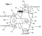
- the setting device 20 shown in the figures is used for automatic length compensation for cables 3, 12, 13 with which for example the vehicle brakes by means of an actuating element, like hand brake lever, can be operated.
- the Adjustment device 20 has a lever device 22 which articulated at one end at a point 24 fixed to the vehicle is. At the other end, the lever device 22 has a receptacle 26 for the cable 3 leading to the actuating element.
- the lever device 22 is provided with a holder 28 connected, the recordings 11 for the leading to the brakes Has cables 12, 13.
- the lever device has two by means of a pivot bearing 14, Swivel joint or the like connected lever arms 2, 7.
- the lever arms 2, 7 are relative by means of a locking mechanism 1 Angular position to each other can be determined.
- the angular position is in Depending on the length compensation.
- the locking mechanism 1 is by a pawl 4 and a set of teeth 6 formed, the toothing 6 on one lever arm 2, 7 arranged and the pawl 4 on the other lever arm 7, 2,
- a bolt 5 or the like pivotally attached are.
- the pawl 4 by means of a Spring element, in particular a tension spring 8, in the locked position biased.
- the teeth 6 and the pawl 4 have one asymmetrical shape, such as sawtooth or the like
- lever arms 2, 7 are by means of a Spring element, in particular tension spring 8, with a bias acted upon.
- the bracket 28 is a balance arm 9 and a Compensation element 10 formed.
- the balance arm 9 is one end pivotally connected to at least one of the lever arms 2, 7.
- the compensating element 10 is at the other end of the Compensating arm 9 is also pivotally articulated.
- the two lever arms 2, 7 at one end at the vehicle-fixed point 24 by means of the pivot bearing 14 or the like.
- the receptacle 26 for the cable 3 is arranged on the first lever arm 2, the bracket 28 with the second lever arm 7 is connected.
- the first lever arm 2 has a slot-like opening 30 through which a Fastening element 32 of the holder 28 on the second lever arm 7 is stuck.
- Figure 2 shows the second lever arm 7 at one end of the vehicle Point 24 articulated and at the other end by means of the pivot bearing 14 or the like. Connected to the first lever arm 2.
- the recording 26 for the cable 3 is also on the first lever arm 2 arranged, the bracket 28 with the pivot bearing 14 of the Lever arms 2, 7 is connected.
- the embodiment of Figure 2 has compared to that of Figure 1 so far a different construction on, than the pivot bearing 14 for the two lever arms 2, 7 not at the vehicle-fixed point 24, but at the free end of the Lever arm 7 is arranged.
- the toothing 6 also acts of the lever arm 2 with that at the point 24 fixed to the vehicle stored pawl 4 together. Also in that The exemplary embodiment in FIG. 2 is between the lever arm 2 or a nose-shaped approach of the lever arm 2 and the Pawl 4 or the articulated on the point 24 fixed to the vehicle Lever arm 7 a tension spring 8 tensioned.
- Adjustment device 20 has in common that due to the Use of a lever device 22 consisting of two Lever arms 2, 7, if a rope loose occurs in the System the relative angular position of the lever arms 2, 7 such is changed that the distance between the recordings 11 and 26th ultimately shortened and thus the rope loose from the system is taken.
- the lever arms 2, 7 are by means of the tension spring 8 towards shortening the distance between the Images 11 and 26 preloaded, the locking mechanism 1 for this ensures that, on the one hand, the ropes are automatically removed from the system removed and on the other hand for a secure fixation of the the respective angular position of the two lever arms 2, 7 is taken care of, as soon as by actuating the actuating element by means of the Cable 3 exerted a tensile force on the lever device 22 becomes.
Landscapes
- Engineering & Computer Science (AREA)
- Mechanical Engineering (AREA)
- General Engineering & Computer Science (AREA)
- Transportation (AREA)
- Health & Medical Sciences (AREA)
- Oral & Maxillofacial Surgery (AREA)
- Flexible Shafts (AREA)
- Mechanical Control Devices (AREA)
- Braking Elements And Transmission Devices (AREA)
Abstract
Description
Die Erfindung betrifft eine Einstellvorrichtung mit selbsttätigem Längenausgleich für Betätigungszüge, wie Seilzüge oder dgl., insbesondere zur Betätigung von Fahrzeugbremsen mittels eines Betätigungselements mit einer Hebelvorrichtung, die einends schwenkbar an einem fahrzeugfesten Punkt angelenkt ist und anderenends eine Aufnahme für den zum Betätigungselement führenden Seilzug aufweist und mit der eine Halterung mit Aufnahme für die zu den Bremsen führenden Seilzüge verbunden ist.The invention relates to an adjusting device automatic length compensation for control cables such as cable pulls or the like, in particular for actuating vehicle brakes by means of an actuating element with a lever device, which is articulated at one point to a vehicle-fixed point is and at the other end a recording for the Has actuating element leading cable and with one Bracket with holder for those leading to the brakes Cable is connected.
Bei derartigen Betätigungszügen tritt im allgemeinen das Problem auf, daß sie fertigungsbedingt nicht gleich lang ausgebildet sind, so daß für eine genaue Einstellung ihrer Länge, insbesondere bei dem Einsatz als Betätigungszug für Bremsen, eine Einstellung vorgenommen werden muß. Aufgrund der Längung der Betätigungszüge während des Betriebes und aufgrund von bspw. Spiel der Bremsen selbst bedarf es auch einer Einstellung bzw. Nachstellung der Betätigungszüge während der Nutzungsdauer.In such actuating cables, this generally occurs Problem on that they are not the same length due to production are trained so that for a precise adjustment of their Length, especially when used as an operating cable for Braking, an adjustment must be made. Due to the Elongation of the actuation cables during operation and due to For example, the game of the brakes themselves also requires one Adjustment or readjustment of the actuation cables during the Useful life.
Aus der DE 3741350 A1 ist bereits eine Einstellvorrichtung mit den eingangs genannten Merkmalen bekannt geworden, welche für die Feststellbremse eines Kraftfahrzeuges bestimmt ist. Für den selbsttätigen Ausgleich von Längungen in den Seilen von Feststellbremsen weist die Vorrichtung ein mittels eines Zugseils verstellbares längliches Übertragungsglied auf, an welchem ein doppelarmiges Ausgleichsjoch angeordnet ist, das seinerseits zu jeweils einer Radbremse führende Seilstränge hält. Die Hebelarme des Ausgleichsjochs sind relativ zueinander verschwenkbar gelagert und zur Übertragung von Bremskräften in der einen Schwenkrichtung mittels einer Sperrvorrichtung an einem Verschwenken gehindert. Eine Spannvorrichtung versucht dabei ständig, die Hebelarme des Ausgleichsjochs in die andere Richtung zu verschwenken. Dadurch, daß die Ausgleichs- bzw. Einstellbewegung durch zwei an der Halterung für die zu den Bremsen führenden Seilzüge vorgesehen ist, ist die bekannte Vorrichtung recht kompliziert aufgebaut.DE 3741350 A1 already includes an adjusting device the features mentioned above, which are known for the parking brake of a motor vehicle is determined. For the automatic compensation of elongations in the ropes of Parking brakes, the device has a Adjustable elongated transmission link on, on which is arranged a double-arm compensation yoke, the in turn rope strands leading to a wheel brake holds. The lever arms of the compensation yoke are relative to one another pivoted and for the transmission of braking forces in the one pivoting direction by means of a locking device prevented from pivoting. A jig tried while doing so, the lever arms of the compensating yoke into the other Direction. Because the compensation or Adjustment movement by two on the bracket for the to Brake leading cables is provided is the well-known Device constructed quite complicated.
Weiterhin ist aus der DE 19546931 A1 bereits eine Einstellvorrichtung bekannt, die eine i.w. gehäuseartige Aufnahme mit zwei schwenkbar gelagerten, durch Federelemente vorgespannten Rastsegmenten aufweist. Die Rastsegmente sind jeweils mit einem Seilzug verbindbar. Desweiteren ist ein in einer Aufnahme verschiebbar geführtes Sperrstück vorgesehen, welches bei einer Betätigung des Seilzuges von einer die Rastsegmente entsperrenden Position in eine die Rastsegmente sperrende Position überführbar ist. Obgleich sich diese bekannte Einstellvorrichtung in der Praxis gut bewährt hat, besteht das Bedürfnis nach einer neuen Einstellvorrichtung mit kompakterer Bauform. Hierbei ist auch zu berücksichtigen, daß der für die Einstellvorrichtung vorhandene Bauraum, beispielsweise im Bereich des Betätigungshebels selbst oder im Bereich des Fahrzeuges, in welchem eine Verzweigung der Betätigungszüge zu den beiden Hinterradbremsen vorgesehen ist, unter Umständen nur sehr klein bemessen ist.Furthermore, DE 19546931 A1 already has one Known adjustment device that i.w. case-like Support with two swivel-mounted, by spring elements has prestressed locking segments. The rest segments are each connectable with a cable. Furthermore, an in a receptacle slidably provided, which when the cable is actuated by one Locking segments unlock the position in one of the locking segments blocking position is transferable. Although this known setting device has proven itself in practice, there is a need for a new adjustment device more compact design. It should also be borne in mind that the installation space available for the adjusting device, for example in the area of the operating lever itself or in Area of the vehicle in which a branching of the Actuating cables to the two rear wheel brakes is provided, may be very small.
Der Erfindung liegt demgegenüber die Aufgabe zugrunde, eine Einstellvorrichtung mit kompakter Bauform und konstruktiv einfachem Aufbau zu schaffen.The invention is based on the object, a Adjustment device with a compact design and construction easy to create.
Diese Aufgabe wird bei der Einstellvorrichtung mit den eingangs genannten Merkmalen im wesentlichen dadurch gelöst, daß die Hebelvorrichtung zwei mittels eines Drehlagers, Drehgelenks oder dgl. verbundene Hebelarme aufweist, welche mittels eines Gesperres in einer relativen Winkellage feststellbar sind, wobei die Winkellage in Abhängigkeit von dem jeweiligen Längenausgleich einstellbar ist. Dadurch, daß die Mittel zum selbsttätigen Längenausgleich nicht im Bereich der Halterung, sondern im Bereich der Hebelvorrichtung angeordnet sind, wird eine konstruktiv einfache bzw. unaufwendige Vorrichtung geschaffen, die auch bei einem räumlich beengten Einbauraum in dem jeweiligen Kraftfahrzeug einsetzbar ist.This object is achieved in the adjusting device with the features mentioned above essentially in that the lever device has two lever arms connected by means of a pivot bearing, swivel joint or the like, which can be determined by means of a locking mechanism in a relative angular position, the angular position depending on the respective length compensation is adjustable. Characterized in that the means for automatic length compensation are not arranged in the area of the bracket, but in the area of the lever device, a structurally simple or inexpensive device is created which can also be used in a space-restricted installation space in the respective motor vehicle.
Eine erste vorteilhafte Ausführungsform zeichnet sich dadurch aus, daß die zwei Hebelarme jeweils einends an dem fahrzeugfesten Punkt mittels des Drehlagers oder dgl. angelenkt sind.A first advantageous embodiment is characterized by this from that the two lever arms at one end of the point fixed to the vehicle by means of the pivot bearing or the like are.
Dabei bietet es sich an, daß die Aufnahme für den Seilzug zum Bremsgeber am ersten Hebelarm angeordnet und die Halterung für die Seilzüge zu den Radbremsen mit dem zweiten Hebelarm verbunden ist.It makes sense that the cable for the cable to Brake sensor arranged on the first lever arm and the holder for the cables to the wheel brakes with the second lever arm connected is.
Es hat sich weiterhin als vorteilhaft erwiesen, daß der erste Hebelarm eine langlochartige Durchbrechung aufweist, durch welche ein Befestigungselement der Halterung am zweiten Hebelarm gesteckt ist. Hierdurch ist eine freie Verschwenkbarkeit bzw. Änderung der relativen Winkellage der beiden Hebelarme im Falle der Längung eines Seilzuges ohne weiteres möglich.It has also proven advantageous that the first Lever arm has a slot-like opening, through which is a fastener of the bracket on the second Lever arm is inserted. This is a free one Swiveling or changing the relative angular position of the two lever arms in the case of the extension of a cable without further possible.
Nach einer weiteren Ausführungsform der Erfindung bietet es sich an, daß der zweite Hebelarm einends an dem fahrzeugfesten Punkt angelenkt und anderenends mittels des Drehlagers oder dgl. mit dem ersten Hebelarm verbunden ist. In diesem Falle besteht die Möglichkeit, die Halterung fest mit dem Drehlager der beiden Hebelarme zu verbinden.According to a further embodiment of the invention, it offers suppose that the second lever arm at one end on the vehicle Point articulated and at the other end using the pivot bearing or Like. Is connected to the first lever arm. In this case it is possible to fix the bracket to the pivot bearing to connect the two lever arms.
Erfindungsgemäß kann die Aufnahme für den Seilzug am ersten Hebelarm angeordnet und die Halterung mit dem Drehlager der Hebelarme verbunden sein. According to the invention for the cable on the first Lever arm arranged and the bracket with the pivot bearing Lever arms are connected.
Das Gesperre ist nach einer Ausführungsform der Erfindung durch eine Sperrklinke sowie eine entsprechend angepaßte Zahnung gebildet, wobei die Zahnung an dem einen Hebelarm angeordnet und die Sperrung an dem anderen Hebelarm, bspw. mittels eines Bolzens oder dgl., schwenkbar befestigt sind.The locking mechanism is in accordance with one embodiment of the invention a pawl and a correspondingly adapted toothing formed, the teeth arranged on the one lever arm and locking on the other lever arm, for example by means of a Bolzens or the like. Are pivotally attached.
Es bietet sich weiterhin an, daß die Sperrklinke mittels eines Federelements, insbesondere einer Zugfeder oder dgl. in Sperrstellung vorgespannt ist.It also makes sense that the pawl by means of a Spring element, in particular a tension spring or the like. In Locked position is biased.
Von Vorteil weisen die Zahnung bzw. die Sperrklinke eine asymmetrische Formgebung, wie Sägezahn oder dgl. auf. Hierdurch ist bei einer Betätigung des Betätigungselements mit der damit einhergehenden Schwenkung der Hebelvorrichtung für eine sichere Festlegung der relativen Winkellage der beiden Hebelarme gesorgt, während im Falle der Nichtbetätigung des Hebelelements und einer unter Umständen erforderlich werdenden Längenkompensation die relative Winkellage der beiden Hebelarme ohne weiteres änderbar ist, indem die Sperrklinke sozusagen über die Zahnung des einen Hebelarmes hinwegratscht, bis die beiden Hebelarme eine neue, relative Winkellage zum Längenausgleich angenommen haben.The teeth or the pawl advantageously have one asymmetrical shape, such as sawtooth or the like. Hereby is with an actuation of the actuating element accompanying pivoting of the lever device for a safe Determination of the relative angular position of the two lever arms worried while in the event of non-actuation of the lever element and one that may become necessary Length compensation is the relative angular position of the two lever arms can easily be changed by the pawl so to speak ratchets over the teeth of one lever arm until the two lever arms a new, relative angular position to Have accepted length compensation.
Hierzu hat es sich desweiteren als äußerst vorteilhaft erwiesen, daß die Hebelarme mittels eines Federelements, insbesondere der Zugfeder, mit einer Vorspannung beaufschlagt sind. Dabei wirkt die Vorspannung im Sinne einer effektiven Verkürzung der Länge der Seilzüge, so daß insbesondere jegliche Lose in dem Einstellsystem ausgeglichen werden können.For this purpose, it has also proven to be extremely advantageous proved that the lever arms by means of a spring element, in particular the tension spring, with a bias are. The preload works in the sense of an effective one Shortening the length of the cables, so that in particular any Loose in the adjustment system can be compensated.
Die Halterung ist von Vorteil durch einen Ausgleichsarm und ein Ausgleichselement gebildet, wobei das Ausgleichselement in etwa mittig an den Ausgleichsarm angelenkt ist und an den beideseitigen Enden die Aufnahme für die zu den Bremsen führenden Seilzüge trägt. The bracket is advantageous by a balance arm and a Compensation element formed, the compensation element approximately is articulated in the middle of the compensating arm and on the both ends of the receptacle for the brakes leading cables.
Dadurch, daß der Ausgleichsarm einends mit wenigstens einem Hebelarm schwenkbar verbunden ist, werden Änderungen in der Winkellage der Hebelvorrichtung sozusagen selbsttätig kompensiert.The fact that the compensating arm ends with at least one Lever arm is pivotally connected, changes in the Angular position of the lever device, so to speak, automatically compensated.
Es bietet sich auch an, daß das Ausgleichselement mit den anderen Ende des Ausgleichsarms schwenkbar verbunden ist, so daß unterschiedliche Längungen in den zu den Bremsen führenden Seilzügen durch ein entsprechendes Verschwenken des Ausgleichselements an dem Ausgleichsarm kompensiert werden können.It also makes sense that the compensating element with the other end of the balance arm is pivotally connected, so that different elongations in the leading to the brakes Cable pulls by swiveling the Compensating elements are compensated for on the compensating arm can.
Weitere Ziele, Merkmale, Vorteile und Anwendungsmöglichkeiten der vorliegenden Erfindung ergeben sich aus der nachfolgenden Beschreibung der Ausführungsbeispiele. Dabei bilden alle beschriebenen und/oder bildlich dargestellten Merkmale für sich oder in beliebiger sinnvoller Kombination den Gegenstand vorliegender Erfindung, auch unabhängig von ihrer Zusammenfassung in den Ansprüchen oder deren Rückbeziehung.Further goals, features, advantages and possible applications of the present invention result from the following Description of the embodiments. Thereby everyone described and / or illustrated features for themselves or the object in any meaningful combination The present invention, regardless of its Summary in the claims or their relationship.
Es zeigen:
- Figur 1
- ein erstes Ausführungsbeispiel der Erfindung in Seitenansicht und schematischer Darstellung und
Figur 2- ein zweites Ausführungsbeispiel der Erfindung in Seitenansicht und schematischer Darstellung.
- Figure 1
- a first embodiment of the invention in side view and schematic representation and
- Figure 2
- a second embodiment of the invention in side view and schematic representation.
Die in den Figuren dargestellt Einstellvorrichtung 20 dient zum
selbsttätigen Längenausgleich für Seilzüge 3, 12, 13, mit denen
bspw. die Fahrzeugbremsen mittels eines Betätigungselements,
wie Handbremshebel, betätigt werden können. Die
Einstellvorrichtung 20 weist eine Hebelvorrichtung 22 auf, die
einends schwenkbar an einem fahrzeugfesten Punkt 24 angelenkt
ist. Anderenends besitzt die Hebelvorrichtung 22 eine Aufnahme
26 für den zum Betätigungselement führenden Seilzug 3. The
Weiterhin ist die Hebelvorrichtung 22 mit einer Halterung 28
verbunden, die Aufnahmen 11 für die zu den Bremsen führenden
Seilzüge 12, 13 aufweist.Furthermore, the
Die Hebelvorrichtung besitzt zwei mittels eines Drehlagers 14,
Drehgelenks oder dgl. verbundene Hebelarme 2, 7. Die Hebelarme
2, 7 sind mittels eines Gesperres 1 in einer relativen
Winkellage zueinander feststellbar. Die Winkellage ist in
Abhängigkeit von dem jeweiligen Längenausgleich feststellbar.The lever device has two by means of a pivot bearing 14,
Swivel joint or the like connected
Das Gesperre 1 ist durch eine Sperrklinke 4 sowie eine Zahnung
6 gebildet, wobei die Zahnung 6 an dem einen Hebelarm 2, 7
angeordnet und die Sperrklinke 4 an dem anderen Hebelarm 7, 2,
bspw. mittels eines Bolzens 5 oder dgl., schwenkbar befestigt
sind. Weiterhin ist die Sperrklinke 4 mittels eines
Federelements, insbesondere einer Zugfeder 8, in Sperrstellung
vorgespannt. Die Zahnung 6 bzw. die Sperrklinke 4 besitzen eine
asymmetrische Formgebung, wie Sägezahn oder dgl.The locking mechanism 1 is by a pawl 4 and a set of
Schließlich sind die Hebelarme 2, 7 mittels eines
Federelements, insbesondere Zugfeder 8, mit einer Vorspannung
beaufschlagt.Finally, the
Die Halterung 28 ist durch einen Ausgleichsarm 9 sowie ein
Ausgleichselement 10 gebildet. Der Ausgleichsarm 9 ist einends
mit wenigstens einem der Hebelarme 2, 7 schwenkbar verbunden.
Das Ausgleichselement 10 ist an das andere Ende des
Ausgleichsarms 9 ebenfalls schwenkbar angelenkt.The
Im Ausführungsbeispiel der Figur 1 sind die beiden Hebelarme 2,
7 einends an dem fahrzeugfesten Punkt 24 mittels des Drehlagers
14 oder dgl. angelenkt. Die Aufnahme 26 für den Seilzug 3 ist
am ersten Hebelarm 2 angeordnet, wobei die Halterung 28 mit dem
zweiten Hebelarm 7 verbunden ist. Der erste Hebelarm 2 besitzt
eine langlochartige Durchbrechung 30, durch welche ein
Befestigungselement 32 der Halterung 28 am zweiten Hebelarm 7
gesteckt ist.In the embodiment of Figure 1, the two
Im Unterschied hierzu ist nach dem Ausführungsbeispiel der
Figur 2 der zweite Hebelarm 7 einends an dem fahrzeugfesten
Punkt 24 angelenkt und anderenends mittels des Drehlagers 14
oder dgl. mit dem ersten Hebelarm 2 verbunden. Die Aufnahme 26
für den Seilzug 3 ist ebenfalls am ersten Hebelarm 2
angeordnet, wobei die Halterung 28 mit dem Drehlager 14 der
Hebelarme 2, 7 verbunden ist.In contrast to this, according to the exemplary embodiment
Figure 2 shows the
Wenn eine Seillose im System vorhanden ist, bewirkt die
Zugfeder 8 ein Verschwenken des Hebelarmes 7 in
Uhrzeigerdrehrichtung, wodurch die Halterung 28 zusammen mit
den angelenkten Seilzügen 12, 13 in Richtung des
Betätigungshebels für die Handbremse bzw. die Feststellbremse
verschoben wird und dementsprechend ein Längenausgleich
erfolgt.If there is a rope loose in the system, this causes
Tension spring 8 a pivoting of the
Das Ausführungsbeispiel der Figur 2 weist gegenüber dem der
Figur 1 insoweit einen unterschiedlichen konstruktiven Aufbau
auf, als das Drehlager 14 für die beiden Hebelarme 2, 7 nicht
an dem fahrzeugfesten Punkt 24, sondern an dem freien Ende des
Hebelarmes 7 angeordnet ist. Weiterhin wirkt die Verzahnung 6
des Hebelarms 2 mit der an dem fahrzeugfesten Punkt 24
gelagerten Sperrklinke 4 zusammen. Auch in dem
Ausführungsbeispiel der Figur 2 ist zwischen dem Hebelarm 2
bzw. einem nasenförmigen Ansatz des Hebelarms 2 und der
Sperrklinke 4 bzw. den am fahrzeugfesten Punkt 24 angelenkten
Hebelarm 7 eine Zugfeder 8 gespannt.The embodiment of Figure 2 has compared to that of
Figure 1 so far a different construction
on, than the pivot bearing 14 for the two
Beim Auftreten einer Seillose bewirkt die Zugfeder 8 ein
Verschwenken des Hebelarms 2 entgegen dem Uhrzeigerdrehsinn,
wobei der die Zahnung 6 tragende Abschnitt des Hebelarms 2 in
Richtung des Handbremsbetätigungshebels bzw. der
Feststellbremse verschoben wird. Es ist dabei zu
berücksichtigen, daß die Aufnahme 26 des Hebelarms 2 aufgrund
der Anlenkung des zum Betätigungshebel führenden Bremsseils 3
im wesentlichen ortsfest ist.When a rope is released, the
Beiden Ausführungsbeispielen der erfindungsgemäßen
Einstellvorrichtung 20 ist gemeinsam, daß aufgrund des
Einsatzes einer Hebelvorrichtung 22, bestehend aus zwei
Hebelarmen 2, 7, bei einem Auftreten einer Seillose in dem
System die relative Winkellage der Hebelarme 2, 7 derart
geändert wird, daß der Abstand zwischen den Aufnahmen 11 und 26
letztlich verkürzt und somit die Seillose aus dem System
genommen wird. Die Hebelarme 2, 7 sind mittels der Zugfeder 8
in Richtung einer Verkürzung des Abstandes zwischen den
Aufnahmen 11 und 26 vorgespannt, wobei das Gesperre 1 dafür
sorgt, daß zum einen die Seillose selbsttätig aus dem System
herausgenommen und andererseits für eine sichere Fixierung der
jeweiligen Winkellage der beiden Hebelarme 2, 7 gesorgt wird,
sobald durch Betätigung des Betätigungselementes mittels des
Seilzuges 3 eine Zugkraft auf die Hebelvorrichtung 22 ausgeübt
wird. Both embodiments of the
- 11
- GesperreLock
- 22nd
- HebelarmLever arm
- 33rd
- SeilzugCable
- 44th
- SperrklinkePawl
- 55
- Bolzenbolt
- 66
- ZahnungPerforation
- 77
- HebelarmLever arm
- 88th
- ZugfederTension spring
- 99
- AusgleichsarmCompensation arm
- 1010th
- AusgleichselementCompensating element
- 1111
- AufnahmenRecordings
- 1212th
- SeilzugCable
- 1313
- SeilzugCable
- 1414
- DrehlagerPivot bearing
- 2020th
- EinstellvorrichtungAdjusting device
- 2222
- HebelvorrichtungLever device
- 2424th
- fahrzeugfester Punktfixed point
- 2626
- Aufnahmeadmission
- 2828
- Halterungbracket
- 3030th
- DurchbrechungBreakthrough
- 3232
- BefestigungselementFastener
Claims (13)
Applications Claiming Priority (4)
| Application Number | Priority Date | Filing Date | Title |
|---|---|---|---|
| DE19715307 | 1997-04-11 | ||
| DE19715307 | 1997-04-11 | ||
| DE19734573A DE19734573C2 (en) | 1997-04-11 | 1997-08-09 | Adjustment device with automatic length compensation for wire rope hoists, especially for vehicle brakes |
| DE19734573 | 1997-08-09 |
Publications (2)
| Publication Number | Publication Date |
|---|---|
| EP0870660A2 true EP0870660A2 (en) | 1998-10-14 |
| EP0870660A3 EP0870660A3 (en) | 1999-05-06 |
Family
ID=26035725
Family Applications (1)
| Application Number | Title | Priority Date | Filing Date |
|---|---|---|---|
| EP98106248A Withdrawn EP0870660A3 (en) | 1997-04-11 | 1998-04-06 | Device for automatic lenght adjustment for an actuating cable, especially for motor vehicles |
Country Status (1)
| Country | Link |
|---|---|
| EP (1) | EP0870660A3 (en) |
Families Citing this family (1)
| Publication number | Priority date | Publication date | Assignee | Title |
|---|---|---|---|---|
| DE102005000804B4 (en) * | 2005-01-05 | 2011-06-16 | FICO CABLES S.A. Technological Centre Pujol & Tarragó | Handbrake lever system |
Citations (3)
| Publication number | Priority date | Publication date | Assignee | Title |
|---|---|---|---|---|
| US2907228A (en) * | 1955-03-07 | 1959-10-06 | American Forging & Socket Co | Hand brake system |
| DE3741530A1 (en) * | 1987-12-08 | 1989-06-29 | Daimler Benz Ag | Readjustment device for a parking brake of a motor vehicle |
| DE19718320A1 (en) * | 1996-05-07 | 1997-11-13 | Kuester & Co Gmbh | Adjustment device for vehicle brakes draw cable system |
-
1998
- 1998-04-06 EP EP98106248A patent/EP0870660A3/en not_active Withdrawn
Patent Citations (3)
| Publication number | Priority date | Publication date | Assignee | Title |
|---|---|---|---|---|
| US2907228A (en) * | 1955-03-07 | 1959-10-06 | American Forging & Socket Co | Hand brake system |
| DE3741530A1 (en) * | 1987-12-08 | 1989-06-29 | Daimler Benz Ag | Readjustment device for a parking brake of a motor vehicle |
| DE19718320A1 (en) * | 1996-05-07 | 1997-11-13 | Kuester & Co Gmbh | Adjustment device for vehicle brakes draw cable system |
Also Published As
| Publication number | Publication date |
|---|---|
| EP0870660A3 (en) | 1999-05-06 |
Similar Documents
| Publication | Publication Date | Title |
|---|---|---|
| DE10154659C5 (en) | Collapsible steering column assembly for a vehicle | |
| DE2160278C2 (en) | Self-adjusting actuator for a motor vehicle clutch | |
| DE102007059744A1 (en) | Transmission unit of an adjustment of a motor vehicle | |
| DE4211566A1 (en) | Handbrake provided with an automatic adjustment device | |
| EP0754135B1 (en) | Parking brake for motor vehicles, trailers, etc. | |
| EP3915829B1 (en) | Vehicle seat fitting and vehicle seat | |
| DE19936733C2 (en) | Actuator for a parking brake | |
| EP1851085B1 (en) | Device for locking and unlocking and automotive vehicle seat with such a device | |
| EP0300470A1 (en) | Device for fastening a safety belt lock support to a recipient affixed to a vehicle | |
| EP0904990A1 (en) | Actuating unit | |
| EP0904223B1 (en) | Regulator for automatically adjusting the length of an actuating link | |
| DE19734573C2 (en) | Adjustment device with automatic length compensation for wire rope hoists, especially for vehicle brakes | |
| WO2001096161A2 (en) | Parking brake | |
| EP0950589A2 (en) | Vehicle locking apparatus | |
| DE10230855B4 (en) | Pedal assembly and mounting method for this | |
| EP0870660A2 (en) | Device for automatic lenght adjustment for an actuating cable, especially for motor vehicles | |
| DE102005010211A1 (en) | Parking lock mechanism for use in motor vehicle, has casing radially arranged between connection rod and blocking device that is arranged on outer diameter of casing and is not spring-mounted and not pre-stressed and freely rotated | |
| DE19600582B4 (en) | Parking brake for a motor vehicle | |
| DE19718320C2 (en) | Adjustment device with automatic length compensation for a cable system or the like | |
| DE102004040881B4 (en) | vehicle seat | |
| DE19734572C2 (en) | Adjustment device with automatic length compensation for an operating cable | |
| DE19911589C1 (en) | Vehicle seat has operating device with counter element opposing swivel movement of operating lever with high force initially and then lesser force to prevent swivelling in event of crash forces | |
| DE10142344B4 (en) | Adjustment device for a control cable | |
| EP1705044B1 (en) | Device to fix a slidable shade system | |
| EP0771706B1 (en) | Actuating device for a handbrake |
Legal Events
| Date | Code | Title | Description |
|---|---|---|---|
| PUAI | Public reference made under article 153(3) epc to a published international application that has entered the european phase |
Free format text: ORIGINAL CODE: 0009012 |
|
| AK | Designated contracting states |
Kind code of ref document: A2 Designated state(s): DE ES FR GB IT SE |
|
| AX | Request for extension of the european patent |
Free format text: AL;LT;LV;MK;RO;SI |
|
| PUAL | Search report despatched |
Free format text: ORIGINAL CODE: 0009013 |
|
| AK | Designated contracting states |
Kind code of ref document: A3 Designated state(s): AT BE CH CY DE DK ES FI FR GB GR IE IT LI LU MC NL PT SE |
|
| AX | Request for extension of the european patent |
Free format text: AL;LT;LV;MK;RO;SI |
|
| AKX | Designation fees paid |
Free format text: DE ES FR GB IT SE |
|
| STAA | Information on the status of an ep patent application or granted ep patent |
Free format text: STATUS: THE APPLICATION IS DEEMED TO BE WITHDRAWN |
|
| 18D | Application deemed to be withdrawn |
Effective date: 19991109 |