EP0868381B1 - Blattförmige produkte für einen spender und verfahren zur herstellung derselben aus quergereckten materialbahnen - Google Patents
Blattförmige produkte für einen spender und verfahren zur herstellung derselben aus quergereckten materialbahnen Download PDFInfo
- Publication number
- EP0868381B1 EP0868381B1 EP96943544A EP96943544A EP0868381B1 EP 0868381 B1 EP0868381 B1 EP 0868381B1 EP 96943544 A EP96943544 A EP 96943544A EP 96943544 A EP96943544 A EP 96943544A EP 0868381 B1 EP0868381 B1 EP 0868381B1
- Authority
- EP
- European Patent Office
- Prior art keywords
- ribbons
- ribbon
- knee
- sheets
- longitudinal axis
- Prior art date
- Legal status (The legal status is an assumption and is not a legal conclusion. Google has not performed a legal analysis and makes no representation as to the accuracy of the status listed.)
- Expired - Lifetime
Links
- 238000000034 method Methods 0.000 title claims abstract description 34
- 238000010924 continuous production Methods 0.000 claims abstract description 3
- 239000000463 material Substances 0.000 claims description 15
- 230000008569 process Effects 0.000 abstract description 7
- 230000003993 interaction Effects 0.000 abstract description 3
- 239000000047 product Substances 0.000 description 19
- 239000006210 lotion Substances 0.000 description 7
- 238000004519 manufacturing process Methods 0.000 description 7
- 239000003599 detergent Substances 0.000 description 4
- 238000005520 cutting process Methods 0.000 description 3
- 239000004744 fabric Substances 0.000 description 3
- 230000007246 mechanism Effects 0.000 description 3
- 238000000926 separation method Methods 0.000 description 3
- 238000004140 cleaning Methods 0.000 description 2
- 230000003247 decreasing effect Effects 0.000 description 2
- 238000012986 modification Methods 0.000 description 2
- 230000004048 modification Effects 0.000 description 2
- 239000002699 waste material Substances 0.000 description 2
- 102100022005 B-lymphocyte antigen CD20 Human genes 0.000 description 1
- 101000897405 Homo sapiens B-lymphocyte antigen CD20 Proteins 0.000 description 1
- 239000004909 Moisturizer Substances 0.000 description 1
- 102000003729 Neprilysin Human genes 0.000 description 1
- 108090000028 Neprilysin Proteins 0.000 description 1
- 229920000297 Rayon Polymers 0.000 description 1
- 230000002745 absorbent Effects 0.000 description 1
- 239000002250 absorbent Substances 0.000 description 1
- 230000006978 adaptation Effects 0.000 description 1
- 239000000654 additive Substances 0.000 description 1
- 239000000853 adhesive Substances 0.000 description 1
- 230000001070 adhesive effect Effects 0.000 description 1
- 239000003795 chemical substances by application Substances 0.000 description 1
- 230000007423 decrease Effects 0.000 description 1
- 230000000694 effects Effects 0.000 description 1
- 239000012467 final product Substances 0.000 description 1
- 230000002452 interceptive effect Effects 0.000 description 1
- 239000000203 mixture Substances 0.000 description 1
- 230000001333 moisturizer Effects 0.000 description 1
- 230000003020 moisturizing effect Effects 0.000 description 1
- 238000004806 packaging method and process Methods 0.000 description 1
- 230000010399 physical interaction Effects 0.000 description 1
- 229920000728 polyester Polymers 0.000 description 1
- 230000002028 premature Effects 0.000 description 1
- 239000002964 rayon Substances 0.000 description 1
- XLYOFNOQVPJJNP-UHFFFAOYSA-N water Substances O XLYOFNOQVPJJNP-UHFFFAOYSA-N 0.000 description 1
Images
Classifications
-
- B—PERFORMING OPERATIONS; TRANSPORTING
- B65—CONVEYING; PACKING; STORING; HANDLING THIN OR FILAMENTARY MATERIAL
- B65H—HANDLING THIN OR FILAMENTARY MATERIAL, e.g. SHEETS, WEBS, CABLES
- B65H37/00—Article or web delivery apparatus incorporating devices for performing specified auxiliary operations
Definitions
- This invention relates to an improved strata arrangement of sheets for use in a pop-up dispensing system, and method for forming sheets from stretched ribbons which are oriented into a substantially continuous strata.
- wipes Disposable towelettes and similar sheet products, sometimes generally referred to as "wipes", which are dispensed from a container, or from individually wrapped packages, have become a fixture in today's society.
- wipes are used for hygienic purposes as well as routine, nonhygienic cleaning and wiping.
- the size, shape, thickness, durability, moisture content, and lotion content of the wipe can all be adjusted for a variety of uses, and the versatility of such products has contributed to the popularity of wipes in general.
- sheet products such as wipes
- dispensing mechanisms There are a variety of dispensing mechanisms that involve containers and some that do not.
- rolls of dry paper towels and toilet paper do not require containers because of their low moisture content.
- “Dry” sheet products often include lotions or other additives and are not necessarily moisture free. Rather “dry” sheet products are sheets with low moisture content that are generally dry to the touch of an average consumer.
- Paper towels and toilet paper are generally in the form of rolled continuous sheets with perforations defining the individual leaves. A consumer unrolls the number of leaves that he or she needs and tears them from the roll along the perforations between leaves.
- wet wipes a popular method for dispensing moistened sheets, "wet wipes", is a combination of the perforated roll and the container dispenser. Ribbons of sheets are often perforated, rolled, placed in a rigid container and then lotions and/or cleansing agents are added. For dispensing, individual wet wipes are generally pulled through a small aperture in the container and then torn along the perforations to remove the sheet. Problems with such arrangements can arise as the dispensing aperture is typically small to minimize evaporative loss of moisturizing agent from the products closest to the top. The smaller sized aperture, in turn, requires an increase in force to withdraw the wipe from the dispenser.
- the increased force can result in premature tearing of perforations between products to be dispensed, or may require designing perforations with increased resistance to tearing, thereby requiring additional force by the user to separate a product for use.
- two hands are required to extract a treated or "wet wipe” (i.e. one hand to remove a wipe and the other to secure the container while the wipe is being removed from the container and torn from the next wipe).
- sheet products such as wipes are often needed when only one hand is available (e.g. when cleaning an infant), which makes perforated wipes dispensed from a container an undesirable combination.
- wipes that are not dispensed from a rigid container
- the individual prepackaged wet wipes often handed out at restaurants or on airplanes. These wet wipes are often folded and placed in individual moisture resistant pouches, then lotion and/or a cleansing agent is added, and the pouch is heat sealed. The consumer tears open the package to use the wipe, and then disposes of both the pouch and the wipe. Typically, this is also a two-handed operation, and there is considerable waste created in the form of the individual pouches, making this method of packaging and dispensing undesirable as well.
- a known manner of dispensing individual (i.e. precut, interfolded, non-perforated) sheets is through a dispensing container.
- the dispensing container can be a box with a lid that is opened each time a sheet is needed, it can be a box with a lid and an aperture that individual sheets are pulled through, or it can be a combination of both a lid and an aperture.
- dry sheets dispensed through a box with an aperture are typically rectangular and interfolded. Tissues and paper towels in restrooms are often dispensed in this manner.
- dispensing an interfolded sheet involves pulling one edge of an essentially rectangular sheet away from the dispenser.
- the interleaved portion of the two sheets serves to pull the adjacent portion of the next sheet due to the interfacial interaction of the two sheets at the overlap area.
- the two interfolded sheets begin to quickly separate.
- the portion of the second sheet remaining above the dispenser is commonly referred to as the "tail".
- Dry sheets or tissues dispensed in this manner generally have a large overlap area consisting of an entire side of the rectangular sheet interfolded with an edge of the next sheet.
- the large surface area of overlap often results in excessive interactive forces between the two sheets, causing a second sheet to be dispensed along with the first sheet due to the larger force required to separate the two sheets. Decreasing the surface area of overlap is difficult because this decreases the adhesive force, which controls the amount of the second sheet removed from the dispenser (to provide the "tail" for subsequent dispensing).
- U.S. Patent No. 5,332,118 to Muckenfuhs discloses a series of designs for sheets that can be folded and used in a pop-up dispensing mechanism without the dispensing difficulties discussed above.
- An improved method for forming sheet products, as described in the '118 patent, for use in pop-up dispensing applications is provided herein wherein knee-like protrusions are formed on the edge of the sheet material by stretching.
- the knee-like protrusions of one ribbon are aligned in a predetermined manner with the protrusions of an adjacent ribbon, and overlapping those aligned ribbons to create predetermined areas of greatest overlap and least overlap therebetween.
- the aligned and overlapped ribbons are then folded into continuous stacks and then cut into discret blocks of interleaved individual sheets for use in a pop-up dispensing system.
- a method of forming ribbons having a longitudinal axis and two opposing side edges then stretching one side edge of the ribbons to form one or more knee-like protrusions therealong.
- the opposing side edge of the ribbon remains essentially parallel to the longitudinal axis of the ribbon.
- the knee-like protrusions of one ribbon are aligned with the essentially parallel side edge of an adjacent ribbon. Ribbons aligned in this manner are then overlapped, creating an area of greatest overlap between the knee-like protrusions of one ribbon and the essentially parallel edge of the adjoining ribbon.
- Each area of greatest overlap is adjoined by an area of least overlap between adjoining ribbons.
- ribbons can be overlapped in this manner forming a substantially continuous strata of ribbons which is then folded into a continuous stack of interleaved ribbons.
- the continuous stack is then cut in a direction essentially normal to the longitudinal axis of the ribbons forming discreet blocks of individual interleaved sheets.
- the substantially continuous stacks are cut near the midpoint at each knee-like protrusion, and cut again approximately halfway between knee-like protrusions.
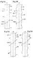
- FIG. 1A illustrates a partial plan view of a ribbon R1 with two opposing side edges 12 and 14 deposed about a longitudinal axis L1.
- a plurality of periodically spaced force, arrows e.g. 16 and 18.
- the forces indicated by arrows 16 and 18 are shown approximately perpendicular to the longitudinal axis L1 of the ribbon R1 and substantially perpendicular to the relatively parallel side edges 12 and 14 of ribbon R1 prior to stretching.
- knee-like protrusions are a portion of the fabric material that, after the fabric has been stretched, extends further from the longitudinal axis of the ribbon than the side edge prior to stretching.
- Muckenfuhs patent A variety of alternatives for the shapes and designs of knee-like protrusions can be found in the aforementioned Muckenfuhs patent.
- the cross directional width of a ribbon CD10 prior to stretching is the distance from the point on one edge 14 of a ribbon R1 where a stretching force 16 will be applied, to the nearest point on the opposing side edge 12 where a stretching force 18 will be applied.
- FIG. 1B further shows a ribbon R1 with two side edges 12 and 14 deposed about a longitudinal axis L1 which has been stretched to increase the cross-directional width CD20.
- Adjoining each knee-like protrusion 20 and 21 is a corresponding recess, or cavity 22 and 23 respectively, which represents the area of the ribbon that has not been stretched or is on the opposing side edge (e.g. 23) from a point where a stretching force has been applied and a knee-like protrusion has been formed (e.g. 20).
- FIG. 2A is another partial plan view of a ribbon R2 having two opposing side edges 212 and 214 centered about a longitudinal axis L2 with the direction of the stretching forces shown with arrows (e.g. 26 and 28).
- ribbons can be stretched in any manner that effectively produces the knee-like protrusions on at least one side edge.
- Forces 26 and 28 are angled but generally in a direction away from the longitudinal axis L2, as are 16 and 18 of FIG. 1A, and both will produce the knee-like protrusion (e.g. FIG. 1B, 20 and 21). It is likely that the shape of the knee-like protrusions (e.g., FIG. 2B, 29) formed by angular forces (e.g FIG.
- knee-like protrusions formed by perpendicular forces may not be the same shape as the knee-like protrusions formed by perpendicular forces (e.g. FIG. 1A, 16 and 18).
- the ability to adjust the size and shape of knee-like protrusions formed on the edge of the ribbons may aid a sheet designer in optimizing ribbon edge geometry to produce sheets with superior dispensing qualities.
- Ribbons R1 and R2 can be manufactured by any means currently available.
- the ribbons are manufactured by a continuous process where a wide based web of material is passed through a cutting station and is slit into ribbons having edges essentially parallel to the machine direction of the web. Slitting can be accomplished by a variety of means, e.g. lasers, waterjets, blades, or the like. Ribbons can also be formed by passing a substantially continuous web over a rotating die cutter which slits the web into uniform individual ribbons. It is generally preferable that at least four ribbons be formed from such a relatively wide based web of material
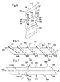
- FIG. 3 shows a plan view of a plurality of adjacent sheets S1, S2 and S3 cut from a ribbon R3 where knee-like protrusions have been formed on one edge 37 of the ribbon R3.
- the opposing side edge 36 is illustrated as being essentially parallel to the longitudinal axis L3 of ribbon R3.
- the ribbon R3 is cut at the approximate mid-point of each knee-like protrusion (i.e., along line 48) and again approximately half way between knee-like protrusions (i.e., along line 51) to form the individual sheets. Sheets stretched and cut in this manner have only one corner 41 on which there is a knee-like protrusion 31 formed.
- FIG. 4 depicts an alternate sheet configuration similar to that shown in FIG. 3, except that knee-like protrusions 32 and 33 are formed on two sides of the ribbon R4 to form individual sheets as depicted by S4, S5 and S6, respectively. There are knee-like protrusions 32 and 33 formed on two of the corners 42 and 43. Corners 46 and 47 are illustrated as preferably located where there are no knee-like protrusions, i.e. comers 46 and 47 are in the recesses or cavities 38 and 39 on the edges of the ribbon R4 which occur approximately half way between adjacent knee-like protrusions.
- Cut lines 49 and 53 are illustrated as situated at the approximate mid-point of each knee-like protrusion 32 and 33, which in this case is also half way between knee-like protrusions on opposing side edges.
- cutting the adjacent sheets S4-S6 at the approximate mid points of knee-like protrusions, and again at points equidistant between each successive knee-like protrusion, is preferred because this method creates two knee-like protrusions on adjacent sheets, from one knee-like protrusion formed on the edge of the ribbon, thus simplifying the manufacturing process.
- FIGs. 3 and 4 show the elongation of the cross-directional distance when the ribbons (e.g., R3 and R4) are stretched to form the knee-like protrusions.
- the cross-directional distance CD120 is greater in length than the cross-directional distance CD110, where CD120 is the distance between corners 40 and 41, and where corner 41 contains a knee-like protrusion 31.
- CD110 is the distance between corners 44 and 45, where neither corner has a knee-like protrusion.
- FIG. 4 shows the diagonals CD210 and CD220 of Sheet S5, where the cross-directional CD220 is the distance between corners 42 and 43, both of which have knee-like protrusions (e.g., 32 and 33) formed thereon.
- the cross-directional distance CD220 has been stretched to a length significantly longer than the cross-directional distance CD210.
- the cross-directional distance CD210 is the distance between corners 46 and 47 of sheet S5 where 46 and 47 fall at the approximate mid-point of the recesses or cavities formed between adjacent knee-like protrusions.
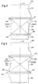
- FIG. 5 is a perspective view of three sheets S7, S8, and S9 made in accordance with the subject invention where the sheets have been overlapped and interfolded.
- the sheets S7, S8, and S9 have been cut from ribbons that were stretched on both sides to form knee-like protrusions (e.g., 84 and 86 of S7) on two corners (e.g., 56 and 54 of sheet S7). Corners 57 and 55 are again preferably located coincidental with the recesses or cavities along the edges 138 and 139 respectively of the sheet S7. Corner 58 of sheet S8 is underlapped with corner 56 of sheet S7 forming the area of overlap 50.
- knee-like protrusions e.g., 84 and 86 of S7
- Corners 57 and 55 are again preferably located coincidental with the recesses or cavities along the edges 138 and 139 respectively of the sheet S7. Corner 58 of sheet S8 is underlapped with corner 56 of sheet S7 forming the area of overlap 50.
- Distance D is equal to the distance between sheet S7 and S8 at the position where there is the least overlap between the two sheets.
- Distance D is a critical dimension discussed in greater detail below with respect to the appropriate interleaving of adjacent overlapping sheets for use in pop-up dispensers and the like. It is crucial to understand that distance D can be a number greater than, less than, or equal to zero, where values for D greater than zero indicate a gap between the two corners (e.g.
- a value of D is equal to zero indicates the two corners (e.g. 57 and 59) touch but do not overlap and where; a value for D is less than zero there is an area of overlap between the two corners (e.g. 57 and 59).
- FIG. 6 is a partial perspective view of a continuous mechanical arrangement for stretching the ribbons of sheet material in accordance with this subject invention.
- the ribbon R5 travels in a predetermined machine direction (e.g., MD) illustrated as being essentially parallel to the longitudinal axis L5 of the ribbon R5, and through a stretching station 66.
- the stretching station 66 comprises individual, uniformly spaced stretching devices (e.g. 60, 61 and 62) which contact the ribbon to apply a stretching forces essentially perpendicular to the longitudinal axis L5, each stretching device applying a force opposite in direction to the stretching devices that adjoins it (e.g. 61 and 62).
- the direction of force applied by stretching devices 61 and 62 are generally indicated by arrows 63 and 64 respectively.
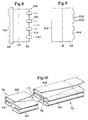
- FIG. 7 shows ribbon R5 after it has been stretched by passing through a stretching station (e.g. FIG. 6, 66).
- the effect of the stretching devices is best seen with respect to the longitudinal axis L5.
- the first knee-like protrusion 121 is formed by stretching device 61 that applies a force in the direction of arrow 163.
- the apex 71 of the knee-like protrusion 121 is significantly further from the longitudinal axis L5 than the area 122 on the opposing side edge 312.
- Adjoining the knee-like protrusion 121 on side edge 314 is a recess or cavity 123 created by stretching device FIG. 6, 62 applying a force in the direction of the arrow 164 on FIG. 7.
- the stretching device 62 creates the knee-like protrusion 120.
- the cross-directional distance from the apex 70 of one knee-like protrusion 120 to the nearest apex 71 of a knee-like protrusion on the opposing edge 121, is CD320.
- the distance between knee-like protrusions on opposing edges is considerably larger than the cross-directional distance CD310 which is the distance between cavities (e.g. 122 and 123) on opposing edges 312 and 314.
- Forming the knee-like protrusions (e.g. 120 and 121) on the edges of a ribbon e.g.
- the cross-directional distances CD320 and CD310 are useful for characterizing the shape of the resulting ribbon prior to overlapping, folding and interleaving of the ribbons before they are cut into individual sheets.
- FIG. 8 shows a partial schematic illustration of a preferred stretching station 166 where a stationary longitudinal clamping device 68 clamps a ribbon R6 near its side edge 412, while a plurality of lateral stretching devices (e.g. 162) are positioned along the opposing side edge 414 of ribbon R6.
- the stretching devices e.g. 162 are moved in a direction indicated by arrows (e.g. 67) generally away from the longitudinal axis L6 in order to form knee-like protrusions (e.g. 220, FIG. 9) on the side edge 414.
- FIG. 9 is a partial plan view of ribbon R6 after it has been stretched in the stretching station 166 as depicted in FIG. 8. Knee-like protrusions (e.g. 220) and corresponding recesses or cavities (e.g., 222) between protrusions are formed on the side edge 414 of ribbon R6. The opposing side edge 412 of ribbon R6 remains essentially parallel to the longitudinal axis L6 as a result of the longitudinal clamping device 68.
- Knee-like protrusions e.g. 220
- corresponding recesses or cavities e.g., 222
- a plurality of substantially identical ribbons are aligned and overlapped so that a knee-like protrusion on the edge of one ribbon is overlapped with a knee-like protrusion on an adjoining ribbon, or is overlapped with an edge that is essentially parallel with the longitudinal axis of the ribbon.
- the strata is folded and cut into individual blocks which are essentially a folded strata of sheets. Therefore the term strata is used to describe the overlapped, layered nature of the sheet material, regardless of whether the material is in the form of ribbons or sheets.
- D is the nominal distance from one sheet edge (e.g., 238 of S8) to the adjoining sheet edge (e.g., 139 of S7) at the point of least overlap.
- the distance D can be greater than, less than, or equal to zero to account for a gap between the comers of adjoining sheets, an area of overlap between the corners of the sheets, or when the corners of adjoining sheets touch but do not overlap, respectively.
- a target distance for D might be from about 2mm to approximately 12mm at the point of least overlap, or more preferably between about 5mm and 7mm.
- the size and shape of the protruding area, and subsequently the size and shape of the area of overlap, can also be adjusted while maintaining a constant gap distance D.
- the Muckenfuhs Patent (the '118 patent), incorporated herein by reference, discusses the overlapping, interleaving and dispensing of sheets in detail. Although the sheet products, and method of manufacture of the present invention are not discussed in Muckenfuhs, the general principles of areas of greatest overlap and least overlap between sheets is applicable to the present invention.
- An example web material that is suitable for making the ribbons of the present invention which is soft, highly stretchable (in the cross-machine direction) and nonwoven has properties (on a dry basis) of: PROPERTY UNITS RESULT Grab Tensile, MD Dry grams 7536 Grab Tensile, CD Dry grams 2497 MD Dry Grab Stretch % 37.3 CD Dry Grab Stretch % 178.5 Basis Weight g/sq m 61.5 Absorbent Capacity g / g 11.1 Sink Time seconds 1.3 Cantilever Drape, MD meters 0.067 Cantilever Drape, CD meters 0.029 Thickness, Ames microns 704
- Such a material is commercially available from Veratec, 100 Elm Street, Walpole, MA under the trade name "HEF #BD94-18".
- This example material is a 50/50 blend of polyester and rayon and is consolidated by hydroentanglement.
- the number of ribbons in a stack determines the number of sheets in a block.
- the desired number of sheets in the final block can be obtained by overlapping a corresponding number of ribbons (e.g. to produce an eighty count box of tissues, eighty ribbons are stacked and interfolded and each block cut therefrom will contain eighty tissues).
- a clip is a stack of sheets that is smaller in number than the desired final product.
- Clip folding and stacking machines common to the art produce stacks of four to ten ribbons which can be cut into clips of four to ten sheets.
- An appropriate number of clips are stacked one on top of the other and each clip is interleaved, or releasably attached to adjoining clips so that a block of a predetermined number of sheets is formed.
- Cutting the continuous stack (e.g., 75, FIG. 10) into discreet blocks (e.g., 76 FIG. 10) of individual interleaved sheets (e.g., S10 and S11) is preferably undertaken at the approximate mid-point of each knee-like protrusion, and approximately halfway between knee-like protrusions, e.g. FIG. 3, 48 and 51 respectively, in a direction essentially perpendicular to the longitudinal axis (e.g. L3 of ribbon R3).
- This method is preferred because each knee-like protrusion that is formed by stretching the ribbon is cut into two knee-like protrusions, one on each adjoining sheet.
- the number of knee-like protrusions that must ultimately be formed is reduced by half.
- any cut line that produces an area of greatest overlap adjacent an area of least overlap along the interleaved edges between adjoining sheets is an acceptable cut line.
- the individual blocks (e.g., 76) of folded interleaved sheets are placed in dispensers where one sheet at a time can be dispensed, leaving a convenient tail for the next dispensing.
- lotion which may contain moisturizers, cleansing agents, water, etc.
- lotion can be added at any convenient point during the manufacturing process.
- the tail of the first sheet is pulled through and away from the dispenser, which in turn pulls the overlapped section through the aperture of the dispenser.
- the physical interaction between the sheet being dispensed and the next sheet in the dispenser causes the two sheets to bond together long enough to remove the area of greatest overlap from the dispenser. As the area of greatest overlap has been removed, a separation front is created at the area of least overlap. As the interaction between the two sheets is decreased, the separation front continues through the interface between the two sheets. The separation front continues until the two sheets are separated leaving a convenient tail of the next sheet remaining above the container.
Landscapes
- Absorbent Articles And Supports Therefor (AREA)
- Folding Of Thin Sheet-Like Materials, Special Discharging Devices, And Others (AREA)
- Vaporization, Distillation, Condensation, Sublimation, And Cold Traps (AREA)
- Shaping By String And By Release Of Stress In Plastics And The Like (AREA)
- Laminated Bodies (AREA)
- Orthopedics, Nursing, And Contraception (AREA)
- Blow-Moulding Or Thermoforming Of Plastics Or The Like (AREA)
- Collation Of Sheets And Webs (AREA)
- Making Paper Articles (AREA)
- Shaping Of Tube Ends By Bending Or Straightening (AREA)
Claims (6)
- Verfahren zur Ausbildung einer Schichtung sich überlappender Blätter, die für die Verwendung in einem automatischen Abgabesystem (pop-up dispensing system) geeignet sind, wobei das Verfahren die folgenden Schritte umfaßt:Ausbilden einer Vielzahl von Bändern des Blattmaterials, wobei jedes Band (R1) eine Längsachse (L1) und einander gegenüberliegende erste und zweite Seitenteile und erste und zweite Seitenkanten (12, 14), die quer von dieser Längsachse beabstandet sind, umfaßt, wobei die erste Seitenkante (12) einen oder mehrere knieförmige Vorsprünge (20, 21) aufweist, und die zweite Seitenkante (14) entweder im wesentlichen parallel mit der Längsachse (L1) ist oder einen oder mehrere knieförmige Vorsprünge (20, 21), die sich von der Längsachse (L1) in entgegengesetzter Richtung von dem Vorsprung (20) auf der ersten Seite (12) nach außen erstrecken, aufweist, dadurch gekennzeichnet, daßdie knieförmigen Vorsprünge (20, 21) auf einer Kante des Bandes (R1) durch das Dehnen des Kantenteils in einer Richtung, die im wesentlichen weg von der Längsachse (L1) verläuft, ausgebildet werden, wobei die Abmessung des Bandes in Querrichtung erhöht wird;Ausrichten von zwei oder mehr der Bänder nebeneinander;Überlappen mindestens eines Teils des knieförmigen Vorsprungs (20) des ersten Seitenteils mit dem zweiten Seitenteil der nebeneinander liegenden Bänder, um eine Schichtung überlappter Bänder zu bilden, um eine Serie von Gebieten einer größten Überlappung (50) neben Gebieten einer geringsten Überlappung (52) auszubilden;Falten der Schichtung der überlappten Bänder, um einen Stapel gefalteter überlappter Bänder zu bilden; undSchneiden des Stapels gefalteter überlappter Bänder quer zur Längsachse, um eine Vielzahl von Blöcken einzelner überlappter Blätter auszubilden.
- Verfahren nach Anspruch 1, wobei es weiter dadurch gekennzeichnet ist, daß benachbarte Bänder in einer Richtung zu ihrer Längsachse ausgerichtet werden, so daß ein knieförmiger Vorsprung (20) auf einer erste Seitenkante (12) eines Bandes mit entweder der im wesentlichen parallelen zweiten Seitenkante oder einem entsprechenden knieförmigen Vorsprung einer zweiten Seitenkante eines benachbarten Bandes ausgerichtet ist, was zu einem vorbestimmten Gebiet der Überlappung zwischen den Seitenkanten benachbarter Bänder führt.
- Verfahren nach einem der Ansprüche 1 oder 2, wobei es weiter dadurch gekennzeichnet ist, daß die Ausbildung und das Dehnen der vielen Bänder in einem im wesentlichen kontinuierlichen Verfahren durchgeführt wird, wobei die Bänder durch eine Dehnstation (66) hindurch geführt werden, in der jedes Band in Querrichtung gedehnt wird, um die knieförmigen Vorsprünge (20, 21) auf den Kantenteilen (12, 14) der Bänder (R1) auszubilden, und wobei die Dehnstation (66) vorzugsweise mindestens eine Dehnvorrichtung (60, 61, 62), die in einer Richtung quer zur Maschinenrichtung bewegt werden kann, um ausgewählt knieförmige Vorsprünge entlang einer Seitenkante der darin ausgebildeten Bänder zu liefern, umfaßt.
- Verfahren nach einem der Ansprüche 1 - 3, wobei die Dehnstation weiter dadurch gekennzeichnet ist, daß mindestens eine Klemmvorrichtung (68), die im wesentlichen relativ zur Längsachse (L1) stationär ist, wenn das Band (R1) in Querrichtung gedehnt wird, um somit eine Seitenkante (12, 14) zu liefern, die im wesentlichen parallel zur Längsachse (L1) eines Bandes verläuft, vorhanden ist.
- Verfahren nach einem der Ansprüche 1 - 4, wobei es weiter dadurch gekennzeichnet ist, daß die Gebiete der geringsten Überlappung (52) zwischen den Bändern Gebiete ohne eine Überlappung zwischen den ausgerichteten Kanten angrenzender Blätter sind.
- Verfahren nach einem der Ansprüche 1 - 5, wobei es weiter dadurch gekennzeichnet ist, daß der Stapel überlappter Bänder in einer Richtung, die im wesentlichen senkrecht zur Längsachse L1 verläuft, und ungefähr am Mittelpunkt jedes überlappenden Vorsprungs und nochmals an Punkten, die äquidistant zwischen jeweils aufeinanderfolgenden überlappenden Vorsprüngen liegen, geschnitten wird, um eine Vielzahl von Blöcken einzelner überlappter Blätter zu bilden.
Applications Claiming Priority (3)
| Application Number | Priority Date | Filing Date | Title |
|---|---|---|---|
| US574437 | 1995-12-15 | ||
| US08/574,437 US5891008A (en) | 1995-12-15 | 1995-12-15 | Sheet products for use in a pop-up dispenser and method for forming from stretched ribbons |
| PCT/US1996/019097 WO1997022544A1 (en) | 1995-12-15 | 1996-11-27 | Improved sheet products for use in a pop-up dispenser and method for forming from stretched ribbons |
Publications (2)
| Publication Number | Publication Date |
|---|---|
| EP0868381A1 EP0868381A1 (de) | 1998-10-07 |
| EP0868381B1 true EP0868381B1 (de) | 2001-08-08 |
Family
ID=24296128
Family Applications (1)
| Application Number | Title | Priority Date | Filing Date |
|---|---|---|---|
| EP96943544A Expired - Lifetime EP0868381B1 (de) | 1995-12-15 | 1996-11-27 | Blattförmige produkte für einen spender und verfahren zur herstellung derselben aus quergereckten materialbahnen |
Country Status (10)
| Country | Link |
|---|---|
| US (1) | US5891008A (de) |
| EP (1) | EP0868381B1 (de) |
| JP (1) | JP2957706B2 (de) |
| KR (1) | KR20000064386A (de) |
| AT (1) | ATE203973T1 (de) |
| AU (1) | AU708760B2 (de) |
| CA (1) | CA2240261A1 (de) |
| DE (1) | DE69614406T2 (de) |
| ES (1) | ES2159775T3 (de) |
| WO (1) | WO1997022544A1 (de) |
Families Citing this family (23)
| Publication number | Priority date | Publication date | Assignee | Title |
|---|---|---|---|---|
| CA2367677A1 (en) * | 1999-03-31 | 2000-10-05 | The Procter & Gamble Company | Pre-moistened wipe with lotion to improve dispensing |
| US6460727B1 (en) | 1999-12-13 | 2002-10-08 | Aram J. Irwin | Pop-up sheet product dispensing system |
| US6565500B1 (en) | 2000-08-08 | 2003-05-20 | The Procter & Gamble Company | Method for batch production of stacks of folded sheets |
| WO2002096255A1 (en) * | 2001-05-31 | 2002-12-05 | Kimberly-Clark Worldwide, Inc. | Stack of fan folded material and combinations thereof |
| US6971542B2 (en) * | 2002-12-13 | 2005-12-06 | Kimberly-Clark Worldwide, Inc. | Reach-in wipes with enhanced dispensibility |
| US6848595B2 (en) * | 2002-12-13 | 2005-02-01 | Kimberly-Clark Worldwide, Inc. | Wipes with a pleat-like zone along the leading edge portion |
| US20050058807A1 (en) * | 2003-09-12 | 2005-03-17 | Hochtritt Robert C. | Stack of interfolded absorbent sheet products |
| US7078087B2 (en) * | 2003-12-31 | 2006-07-18 | Kimberly-Clark Worldwide, Inc. | Wipes with an edge treatment along a leading edge portion |
| US8083097B2 (en) * | 2004-09-30 | 2011-12-27 | Kimberly-Clark Worldwide, Inc | Interleaved towel fold configuration |
| US7097896B2 (en) | 2004-09-30 | 2006-08-29 | Kimberly-Clark Worldwide, Inc. | Interleaved towel fold configuration |
| US20060157495A1 (en) * | 2004-12-23 | 2006-07-20 | Reddy Kiran K K | Easy open folded article |
| US8418879B2 (en) * | 2005-08-31 | 2013-04-16 | Kimberly-Clark Worldwide, Inc. | Pop-up bath tissue product |
| US20070044928A1 (en) * | 2005-08-31 | 2007-03-01 | Kimberly-Clark Worldwide, Inc. | Rolled bath tissue product for children |
| RU2011111395A (ru) * | 2008-08-28 | 2012-10-10 | ДЖОРДЖИЯ-ПЭСИФИК КОНСЬЮМЕР ПРОДАКТС ЭлПи (US) | Сфальцованный листовой материал и совокупность сфальцованных листовых материалов |
| CN102325799A (zh) * | 2009-02-19 | 2012-01-18 | 巴斯夫欧洲公司 | 由乙烯基芳香族化合物、共轭脂肪族二烯和烯键式不饱和酸制备的聚合物水分散体 |
| US20120052316A1 (en) * | 2010-08-27 | 2012-03-01 | Basf Se | Aqueous polymer dispersion obtainable by free-radically initiated emulsion polymerization in the presence of a molecular weight regulator composition |
| US8597761B2 (en) | 2010-10-29 | 2013-12-03 | Sca Hygiene Products Ab | Stack of interfolded absorbent sheet products |
| EP3094766B1 (de) | 2014-01-17 | 2021-09-29 | SixPoint Materials, Inc. | Gruppe-iii-nitrid-massenkristalle und herstellungsverfahren |
| EP3146093A1 (de) | 2014-05-23 | 2017-03-29 | Sixpoint Materials, Inc. | Gruppe-iii-nitrid-massenkristalle und deren herstellungsverfahren |
| JP6526811B2 (ja) | 2014-12-02 | 2019-06-05 | シックスポイント マテリアルズ, インコーポレイテッド | Iii族窒化物結晶を加工する方法 |
| WO2016175888A1 (en) * | 2015-04-30 | 2016-11-03 | Kimberly-Clark Worldwide, Inc. | Method of dispensing a plurality of interconnected wipes |
| JP6474920B2 (ja) | 2015-06-25 | 2019-02-27 | シックスポイント マテリアルズ, インコーポレイテッド | 高圧反応器および超臨界アンモニア中のiii族窒化物結晶の成長方法 |
| JP2021512838A (ja) | 2018-02-09 | 2021-05-20 | シックスポイント マテリアルズ, インコーポレイテッド | 低転位バルクGaN結晶およびこれを製作する方法 |
Family Cites Families (43)
| Publication number | Priority date | Publication date | Assignee | Title |
|---|---|---|---|---|
| US1385569A (en) * | 1920-01-21 | 1921-07-26 | Manifold Printing Company | Method of producing multicopy forms or blanks |
| US1979876A (en) * | 1932-01-06 | 1934-11-06 | Philip A Fischer | Paper napkin |
| US2211494A (en) * | 1939-11-20 | 1940-08-13 | Peter J Christman | Napkin |
| US2353183A (en) * | 1941-07-23 | 1944-07-11 | Fruit & Produce Packing Inc | Basket liner |
| US2477223A (en) * | 1948-01-19 | 1949-07-26 | Wilfred H West | Paper towel |
| US3066932A (en) * | 1959-09-03 | 1962-12-04 | Kimberly Clark Co | Paperfolding machine and method |
| US3172564A (en) * | 1961-05-09 | 1965-03-09 | Kimberly Clark Co | Package of paper tissues |
| US3282525A (en) * | 1963-09-23 | 1966-11-01 | Crown Zellerbach Corp | Web slitting and grooving apparatus and method |
| US3248102A (en) * | 1964-05-14 | 1966-04-26 | Dietz Machine Works | Apparatus and method for producing boxed tissues |
| US3307844A (en) * | 1964-05-21 | 1967-03-07 | Harold L Stults | Interfolding facial tissues |
| GB1030484A (en) * | 1966-05-12 | 1966-05-25 | Francis Edwin Fish | Improvements in or relating to the edge-sealing of thermoplastic woven fabrics |
| GB1199956A (en) * | 1966-07-25 | 1970-07-22 | Kimberly Clark Co | Folding Device |
| US3462043A (en) * | 1966-08-19 | 1969-08-19 | Kimberly Clark Co | Sheet material assembly with interfolded webs including half web folds |
| US3542356A (en) * | 1968-06-14 | 1970-11-24 | Int Paper Co | Web folding apparatus and method |
| US3848501A (en) * | 1973-07-20 | 1974-11-19 | Goodrich Co B F | Fabric cutting |
| US3862610A (en) * | 1974-01-17 | 1975-01-28 | Riegel Textile Corp | Apparatus for cutting and finishing segments of a traveling web |
| US3965785A (en) * | 1975-02-26 | 1976-06-29 | Medical Specialties, Inc. | Apparatus for cutting sheet material |
| US4055697A (en) * | 1975-05-19 | 1977-10-25 | Fiberite Corporation | Woven material with filling threads at angles other than right angles |
| US4002092A (en) * | 1975-06-11 | 1977-01-11 | B & M Die Co., Inc. | Compound angle cutting edge and method of using same |
| US4106166A (en) * | 1976-03-10 | 1978-08-15 | The Stearns & Foster Company | Method for expanding the width of preformed fibrous webs |
| US4010664A (en) * | 1976-03-19 | 1977-03-08 | The Goodyear Tire & Rubber Company | Bias ply cutter feed apparatus |
| CH612478A5 (de) * | 1976-04-30 | 1979-07-31 | Armand Demiere | |
| US4340441A (en) * | 1976-11-16 | 1982-07-20 | Dufaylite Developments Limited | Slicing web material |
| US4131271A (en) * | 1977-06-13 | 1978-12-26 | Paper Converting Machine Company | Method and apparatus for interfolding |
| US4266112A (en) * | 1979-02-14 | 1981-05-05 | Niedermeyer William P | Web-cutting process |
| US4300891A (en) * | 1980-03-27 | 1981-11-17 | Bemiss Robert P | Apparatus for decurling a continuous web |
| FI61454C (fi) * | 1980-12-09 | 1982-08-10 | Nokia Oy Ab | Foerfarande foer stapling av ett gummi- eller plastblandningsband samt en transport- och lagringsstapel av ett dylikt band |
| US4416376A (en) * | 1982-09-30 | 1983-11-22 | Signode Corporation | Bag package and related method |
| US4480772A (en) * | 1983-02-04 | 1984-11-06 | Kimberly-Clark Corporation | Sleeve making method and apparatus |
| DE3336145C2 (de) * | 1983-10-05 | 1985-09-05 | LEMO M. Lehmacher & Sohn GmbH Maschinenfabrik, 5216 Niederkassel | Vorrichtung für die Herstellung von Kunststofftaschen |
| US4574670A (en) * | 1983-11-17 | 1986-03-11 | Lockheed Corporation | Multiple angle cutting apparatus |
| EP0193693B1 (de) * | 1985-03-04 | 1991-12-11 | Mitsubishi Jukogyo Kabushiki Kaisha | Rotierende Schneidvorrichtung |
| US4684259A (en) * | 1985-08-05 | 1987-08-04 | Adolph Coors Company | Epoxy mixing and dispensing apparatus |
| US4664006A (en) * | 1985-09-27 | 1987-05-12 | Swm Corporation | Rotary cutter apparatus |
| US4650451A (en) * | 1985-10-18 | 1987-03-17 | Mobil Oil Corporation | Intermittently translating draw tape stretched between nip rolls |
| US4654180A (en) * | 1985-10-18 | 1987-03-31 | Mobil Oil Corporation | Intermittently stretching thermoplastic with nip rolls |
| US4654021A (en) * | 1985-10-29 | 1987-03-31 | Mobil Oil Corporation | Making intermittent orientation draw tape for bags |
| DE3545270C1 (de) * | 1985-12-20 | 1987-04-23 | Roland Man Druckmasch | Breitstreckvorrichtung |
| DE3714662A1 (de) * | 1987-05-02 | 1988-11-17 | Kronseder Maschf Krones | Verfahren und vorrichtung zum schneiden von konturierten etiketten |
| US5328053A (en) * | 1993-03-22 | 1994-07-12 | The Procter & Gamble Company | Packages for single-use folded towels which provide for unfolding of the towel upon removal from the package |
| US5424025A (en) * | 1993-05-03 | 1995-06-13 | Minnesota Mining And Manufacturing Company | Process of making zone orientated continuous web |
| US5332118A (en) * | 1993-08-17 | 1994-07-26 | The Procter & Gamble Company | Pop-up towel dispensing system |
| US5540332A (en) * | 1995-04-07 | 1996-07-30 | Kimberly-Clark Corporation | Wet wipes having improved dispensability |
-
1995
- 1995-12-15 US US08/574,437 patent/US5891008A/en not_active Expired - Lifetime
-
1996
- 1996-11-27 WO PCT/US1996/019097 patent/WO1997022544A1/en not_active Ceased
- 1996-11-27 ES ES96943544T patent/ES2159775T3/es not_active Expired - Lifetime
- 1996-11-27 KR KR1019980704422A patent/KR20000064386A/ko not_active Abandoned
- 1996-11-27 JP JP9522824A patent/JP2957706B2/ja not_active Expired - Fee Related
- 1996-11-27 EP EP96943544A patent/EP0868381B1/de not_active Expired - Lifetime
- 1996-11-27 CA CA002240261A patent/CA2240261A1/en not_active Abandoned
- 1996-11-27 AT AT96943544T patent/ATE203973T1/de active
- 1996-11-27 AU AU12761/97A patent/AU708760B2/en not_active Ceased
- 1996-11-27 DE DE69614406T patent/DE69614406T2/de not_active Expired - Fee Related
Also Published As
| Publication number | Publication date |
|---|---|
| ATE203973T1 (de) | 2001-08-15 |
| ES2159775T3 (es) | 2001-10-16 |
| JPH11500702A (ja) | 1999-01-19 |
| JP2957706B2 (ja) | 1999-10-06 |
| WO1997022544A1 (en) | 1997-06-26 |
| US5891008A (en) | 1999-04-06 |
| KR20000064386A (ko) | 2000-11-06 |
| DE69614406T2 (de) | 2002-05-29 |
| EP0868381A1 (de) | 1998-10-07 |
| CA2240261A1 (en) | 1997-06-26 |
| AU1276197A (en) | 1997-07-14 |
| AU708760B2 (en) | 1999-08-12 |
| MX9804782A (es) | 1998-10-31 |
| DE69614406D1 (de) | 2001-09-13 |
Similar Documents
| Publication | Publication Date | Title |
|---|---|---|
| EP0868381B1 (de) | Blattförmige produkte für einen spender und verfahren zur herstellung derselben aus quergereckten materialbahnen | |
| EP0865248B1 (de) | Verbesserte faltbare blattprodukte für handtuchspender und verfahren zu ihrer herstellung | |
| US6749083B2 (en) | Stack of fan folded material and combinations thereof | |
| US6905748B2 (en) | Stack of fan folded material and combinations thereof | |
| KR100364342B1 (ko) | 개선된팝업식(pop-up)타월분배시스템 | |
| JP2602433B2 (ja) | 分包ハンカチまたは衛生タオルおよびその製法 | |
| US6991840B2 (en) | Separably joined relationship between adjoining wipes | |
| KR101116508B1 (ko) | 선단 에지 부분을 따라 주름형 구역을 갖는 와이프 | |
| US7081080B2 (en) | Stack of fan folded material and combinations thereof | |
| KR102483756B1 (ko) | 복수의 상호 연결된 티슈를 분배하는 방법 | |
| CA2446661C (en) | Stack of fan folded material and combinations thereof | |
| AU7409998A (en) | Assembly of webs having staggered edge folds | |
| AU2007202525B2 (en) | Stack of fan folded material and combinations thereof | |
| AU2002312158B2 (en) | Stack of fan folded material and combinations thereof | |
| MXPA98004782A (en) | Improved sheet products for use in an automatic supplier and a method for forming them from extended bands | |
| WO2007073244A1 (en) | Dispenser for and method of manufacturing a bundle of interfolded towels and bundle of towels manufactured by the method | |
| AU2002312158A1 (en) | Stack of fan folded material and combinations thereof |
Legal Events
| Date | Code | Title | Description |
|---|---|---|---|
| PUAI | Public reference made under article 153(3) epc to a published international application that has entered the european phase |
Free format text: ORIGINAL CODE: 0009012 |
|
| 17P | Request for examination filed |
Effective date: 19980626 |
|
| AK | Designated contracting states |
Kind code of ref document: A1 Designated state(s): AT BE CH DE DK ES FI FR GB GR IE IT LI LU NL PT SE |
|
| 17Q | First examination report despatched |
Effective date: 19990211 |
|
| GRAG | Despatch of communication of intention to grant |
Free format text: ORIGINAL CODE: EPIDOS AGRA |
|
| GRAG | Despatch of communication of intention to grant |
Free format text: ORIGINAL CODE: EPIDOS AGRA |
|
| GRAH | Despatch of communication of intention to grant a patent |
Free format text: ORIGINAL CODE: EPIDOS IGRA |
|
| GRAH | Despatch of communication of intention to grant a patent |
Free format text: ORIGINAL CODE: EPIDOS IGRA |
|
| GRAA | (expected) grant |
Free format text: ORIGINAL CODE: 0009210 |
|
| AK | Designated contracting states |
Kind code of ref document: B1 Designated state(s): AT BE CH DE DK ES FI FR GB GR IE IT LI LU NL PT SE |
|
| PG25 | Lapsed in a contracting state [announced via postgrant information from national office to epo] |
Ref country code: LI Free format text: LAPSE BECAUSE OF FAILURE TO SUBMIT A TRANSLATION OF THE DESCRIPTION OR TO PAY THE FEE WITHIN THE PRESCRIBED TIME-LIMIT Effective date: 20010808 Ref country code: FI Free format text: LAPSE BECAUSE OF FAILURE TO SUBMIT A TRANSLATION OF THE DESCRIPTION OR TO PAY THE FEE WITHIN THE PRESCRIBED TIME-LIMIT Effective date: 20010808 Ref country code: CH Free format text: LAPSE BECAUSE OF FAILURE TO SUBMIT A TRANSLATION OF THE DESCRIPTION OR TO PAY THE FEE WITHIN THE PRESCRIBED TIME-LIMIT Effective date: 20010808 Ref country code: AT Free format text: LAPSE BECAUSE OF FAILURE TO SUBMIT A TRANSLATION OF THE DESCRIPTION OR TO PAY THE FEE WITHIN THE PRESCRIBED TIME-LIMIT Effective date: 20010808 |
|
| REF | Corresponds to: |
Ref document number: 203973 Country of ref document: AT Date of ref document: 20010815 Kind code of ref document: T |
|
| REG | Reference to a national code |
Ref country code: CH Ref legal event code: EP |
|
| REG | Reference to a national code |
Ref country code: IE Ref legal event code: FG4D |
|
| REF | Corresponds to: |
Ref document number: 69614406 Country of ref document: DE Date of ref document: 20010913 |
|
| ITF | It: translation for a ep patent filed | ||
| REG | Reference to a national code |
Ref country code: ES Ref legal event code: FG2A Ref document number: 2159775 Country of ref document: ES Kind code of ref document: T3 |
|
| PG25 | Lapsed in a contracting state [announced via postgrant information from national office to epo] |
Ref country code: PT Free format text: LAPSE BECAUSE OF FAILURE TO SUBMIT A TRANSLATION OF THE DESCRIPTION OR TO PAY THE FEE WITHIN THE PRESCRIBED TIME-LIMIT Effective date: 20011108 Ref country code: DK Free format text: LAPSE BECAUSE OF FAILURE TO SUBMIT A TRANSLATION OF THE DESCRIPTION OR TO PAY THE FEE WITHIN THE PRESCRIBED TIME-LIMIT Effective date: 20011108 |
|
| PG25 | Lapsed in a contracting state [announced via postgrant information from national office to epo] |
Ref country code: GR Free format text: LAPSE BECAUSE OF FAILURE TO SUBMIT A TRANSLATION OF THE DESCRIPTION OR TO PAY THE FEE WITHIN THE PRESCRIBED TIME-LIMIT Effective date: 20011109 |
|
| ET | Fr: translation filed | ||
| PG25 | Lapsed in a contracting state [announced via postgrant information from national office to epo] |
Ref country code: LU Free format text: LAPSE BECAUSE OF NON-PAYMENT OF DUE FEES Effective date: 20011127 Ref country code: IE Free format text: LAPSE BECAUSE OF FAILURE TO SUBMIT A TRANSLATION OF THE DESCRIPTION OR TO PAY THE FEE WITHIN THE PRESCRIBED TIME-LIMIT Effective date: 20011127 |
|
| REG | Reference to a national code |
Ref country code: GB Ref legal event code: IF02 |
|
| REG | Reference to a national code |
Ref country code: CH Ref legal event code: PL |
|
| PLBE | No opposition filed within time limit |
Free format text: ORIGINAL CODE: 0009261 |
|
| STAA | Information on the status of an ep patent application or granted ep patent |
Free format text: STATUS: NO OPPOSITION FILED WITHIN TIME LIMIT |
|
| 26N | No opposition filed | ||
| REG | Reference to a national code |
Ref country code: IE Ref legal event code: MM4A |
|
| PGFP | Annual fee paid to national office [announced via postgrant information from national office to epo] |
Ref country code: NL Payment date: 20031002 Year of fee payment: 8 |
|
| PGFP | Annual fee paid to national office [announced via postgrant information from national office to epo] |
Ref country code: SE Payment date: 20031106 Year of fee payment: 8 |
|
| PGFP | Annual fee paid to national office [announced via postgrant information from national office to epo] |
Ref country code: ES Payment date: 20031124 Year of fee payment: 8 |
|
| PGFP | Annual fee paid to national office [announced via postgrant information from national office to epo] |
Ref country code: BE Payment date: 20031216 Year of fee payment: 8 |
|
| PG25 | Lapsed in a contracting state [announced via postgrant information from national office to epo] |
Ref country code: SE Free format text: LAPSE BECAUSE OF NON-PAYMENT OF DUE FEES Effective date: 20041128 |
|
| PG25 | Lapsed in a contracting state [announced via postgrant information from national office to epo] |
Ref country code: ES Free format text: LAPSE BECAUSE OF NON-PAYMENT OF DUE FEES Effective date: 20041129 |
|
| PG25 | Lapsed in a contracting state [announced via postgrant information from national office to epo] |
Ref country code: BE Free format text: LAPSE BECAUSE OF NON-PAYMENT OF DUE FEES Effective date: 20041130 |
|
| BERE | Be: lapsed |
Owner name: THE *PROCTER & GAMBLE CY Effective date: 20041130 |
|
| PG25 | Lapsed in a contracting state [announced via postgrant information from national office to epo] |
Ref country code: NL Free format text: LAPSE BECAUSE OF NON-PAYMENT OF DUE FEES Effective date: 20050601 |
|
| EUG | Se: european patent has lapsed | ||
| REG | Reference to a national code |
Ref country code: HK Ref legal event code: WD Ref document number: 1016142 Country of ref document: HK |
|
| NLV4 | Nl: lapsed or anulled due to non-payment of the annual fee |
Effective date: 20050601 |
|
| PG25 | Lapsed in a contracting state [announced via postgrant information from national office to epo] |
Ref country code: IT Free format text: LAPSE BECAUSE OF NON-PAYMENT OF DUE FEES;WARNING: LAPSES OF ITALIAN PATENTS WITH EFFECTIVE DATE BEFORE 2007 MAY HAVE OCCURRED AT ANY TIME BEFORE 2007. THE CORRECT EFFECTIVE DATE MAY BE DIFFERENT FROM THE ONE RECORDED. Effective date: 20051127 |
|
| REG | Reference to a national code |
Ref country code: ES Ref legal event code: FD2A Effective date: 20041129 |
|
| PGFP | Annual fee paid to national office [announced via postgrant information from national office to epo] |
Ref country code: GB Payment date: 20061004 Year of fee payment: 11 |
|
| PGFP | Annual fee paid to national office [announced via postgrant information from national office to epo] |
Ref country code: FR Payment date: 20061103 Year of fee payment: 11 |
|
| PGFP | Annual fee paid to national office [announced via postgrant information from national office to epo] |
Ref country code: DE Payment date: 20061130 Year of fee payment: 11 |
|
| BERE | Be: lapsed |
Owner name: THE *PROCTER & GAMBLE CY Effective date: 20041130 |
|
| GBPC | Gb: european patent ceased through non-payment of renewal fee |
Effective date: 20071127 |
|
| PG25 | Lapsed in a contracting state [announced via postgrant information from national office to epo] |
Ref country code: DE Free format text: LAPSE BECAUSE OF NON-PAYMENT OF DUE FEES Effective date: 20080603 |
|
| REG | Reference to a national code |
Ref country code: FR Ref legal event code: ST Effective date: 20080930 |
|
| PG25 | Lapsed in a contracting state [announced via postgrant information from national office to epo] |
Ref country code: GB Free format text: LAPSE BECAUSE OF NON-PAYMENT OF DUE FEES Effective date: 20071127 |
|
| PG25 | Lapsed in a contracting state [announced via postgrant information from national office to epo] |
Ref country code: FR Free format text: LAPSE BECAUSE OF NON-PAYMENT OF DUE FEES Effective date: 20071130 |