EP0868288B1 - A method of welding or cutting material ultrasonically - Google Patents
A method of welding or cutting material ultrasonically Download PDFInfo
- Publication number
- EP0868288B1 EP0868288B1 EP96940739A EP96940739A EP0868288B1 EP 0868288 B1 EP0868288 B1 EP 0868288B1 EP 96940739 A EP96940739 A EP 96940739A EP 96940739 A EP96940739 A EP 96940739A EP 0868288 B1 EP0868288 B1 EP 0868288B1
- Authority
- EP
- European Patent Office
- Prior art keywords
- anvil
- cylinder
- web
- horn
- welding
- Prior art date
- Legal status (The legal status is an assumption and is not a legal conclusion. Google has not performed a legal analysis and makes no representation as to the accuracy of the status listed.)
- Expired - Lifetime
Links
Images
Classifications
-
- B—PERFORMING OPERATIONS; TRANSPORTING
- B29—WORKING OF PLASTICS; WORKING OF SUBSTANCES IN A PLASTIC STATE IN GENERAL
- B29C—SHAPING OR JOINING OF PLASTICS; SHAPING OF MATERIAL IN A PLASTIC STATE, NOT OTHERWISE PROVIDED FOR; AFTER-TREATMENT OF THE SHAPED PRODUCTS, e.g. REPAIRING
- B29C66/00—General aspects of processes or apparatus for joining preformed parts
- B29C66/80—General aspects of machine operations or constructions and parts thereof
- B29C66/83—General aspects of machine operations or constructions and parts thereof characterised by the movement of the joining or pressing tools
- B29C66/834—General aspects of machine operations or constructions and parts thereof characterised by the movement of the joining or pressing tools moving with the parts to be joined
- B29C66/8341—Roller, cylinder or drum types; Band or belt types; Ball types
- B29C66/83411—Roller, cylinder or drum types
-
- B—PERFORMING OPERATIONS; TRANSPORTING
- B26—HAND CUTTING TOOLS; CUTTING; SEVERING
- B26D—CUTTING; DETAILS COMMON TO MACHINES FOR PERFORATING, PUNCHING, CUTTING-OUT, STAMPING-OUT OR SEVERING
- B26D7/00—Details of apparatus for cutting, cutting-out, stamping-out, punching, perforating, or severing by means other than cutting
- B26D7/08—Means for treating work or cutting member to facilitate cutting
- B26D7/086—Means for treating work or cutting member to facilitate cutting by vibrating, e.g. ultrasonically
-
- B—PERFORMING OPERATIONS; TRANSPORTING
- B29—WORKING OF PLASTICS; WORKING OF SUBSTANCES IN A PLASTIC STATE IN GENERAL
- B29C—SHAPING OR JOINING OF PLASTICS; SHAPING OF MATERIAL IN A PLASTIC STATE, NOT OTHERWISE PROVIDED FOR; AFTER-TREATMENT OF THE SHAPED PRODUCTS, e.g. REPAIRING
- B29C65/00—Joining or sealing of preformed parts, e.g. welding of plastics materials; Apparatus therefor
- B29C65/02—Joining or sealing of preformed parts, e.g. welding of plastics materials; Apparatus therefor by heating, with or without pressure
- B29C65/08—Joining or sealing of preformed parts, e.g. welding of plastics materials; Apparatus therefor by heating, with or without pressure using ultrasonic vibrations
- B29C65/083—Joining or sealing of preformed parts, e.g. welding of plastics materials; Apparatus therefor by heating, with or without pressure using ultrasonic vibrations using a rotary sonotrode or a rotary anvil
- B29C65/086—Joining or sealing of preformed parts, e.g. welding of plastics materials; Apparatus therefor by heating, with or without pressure using ultrasonic vibrations using a rotary sonotrode or a rotary anvil using a rotary anvil
-
- B—PERFORMING OPERATIONS; TRANSPORTING
- B29—WORKING OF PLASTICS; WORKING OF SUBSTANCES IN A PLASTIC STATE IN GENERAL
- B29C—SHAPING OR JOINING OF PLASTICS; SHAPING OF MATERIAL IN A PLASTIC STATE, NOT OTHERWISE PROVIDED FOR; AFTER-TREATMENT OF THE SHAPED PRODUCTS, e.g. REPAIRING
- B29C65/00—Joining or sealing of preformed parts, e.g. welding of plastics materials; Apparatus therefor
- B29C65/74—Joining or sealing of preformed parts, e.g. welding of plastics materials; Apparatus therefor by welding and severing, or by joining and severing, the severing being performed in the area to be joined, next to the area to be joined, in the joint area or next to the joint area
- B29C65/743—Joining or sealing of preformed parts, e.g. welding of plastics materials; Apparatus therefor by welding and severing, or by joining and severing, the severing being performed in the area to be joined, next to the area to be joined, in the joint area or next to the joint area using the same tool for both joining and severing, said tool being monobloc or formed by several parts mounted together and forming a monobloc
- B29C65/7443—Joining or sealing of preformed parts, e.g. welding of plastics materials; Apparatus therefor by welding and severing, or by joining and severing, the severing being performed in the area to be joined, next to the area to be joined, in the joint area or next to the joint area using the same tool for both joining and severing, said tool being monobloc or formed by several parts mounted together and forming a monobloc by means of ultrasonic vibrations
-
- B—PERFORMING OPERATIONS; TRANSPORTING
- B29—WORKING OF PLASTICS; WORKING OF SUBSTANCES IN A PLASTIC STATE IN GENERAL
- B29C—SHAPING OR JOINING OF PLASTICS; SHAPING OF MATERIAL IN A PLASTIC STATE, NOT OTHERWISE PROVIDED FOR; AFTER-TREATMENT OF THE SHAPED PRODUCTS, e.g. REPAIRING
- B29C66/00—General aspects of processes or apparatus for joining preformed parts
- B29C66/80—General aspects of machine operations or constructions and parts thereof
- B29C66/81—General aspects of the pressing elements, i.e. the elements applying pressure on the parts to be joined in the area to be joined, e.g. the welding jaws or clamps
- B29C66/814—General aspects of the pressing elements, i.e. the elements applying pressure on the parts to be joined in the area to be joined, e.g. the welding jaws or clamps characterised by the design of the pressing elements, e.g. of the welding jaws or clamps
- B29C66/8141—General aspects of the pressing elements, i.e. the elements applying pressure on the parts to be joined in the area to be joined, e.g. the welding jaws or clamps characterised by the design of the pressing elements, e.g. of the welding jaws or clamps characterised by the surface geometry of the part of the pressing elements, e.g. welding jaws or clamps, coming into contact with the parts to be joined
- B29C66/81427—General aspects of the pressing elements, i.e. the elements applying pressure on the parts to be joined in the area to be joined, e.g. the welding jaws or clamps characterised by the design of the pressing elements, e.g. of the welding jaws or clamps characterised by the surface geometry of the part of the pressing elements, e.g. welding jaws or clamps, coming into contact with the parts to be joined comprising a single ridge, e.g. for making a weakening line; comprising a single tooth
-
- B—PERFORMING OPERATIONS; TRANSPORTING
- B29—WORKING OF PLASTICS; WORKING OF SUBSTANCES IN A PLASTIC STATE IN GENERAL
- B29C—SHAPING OR JOINING OF PLASTICS; SHAPING OF MATERIAL IN A PLASTIC STATE, NOT OTHERWISE PROVIDED FOR; AFTER-TREATMENT OF THE SHAPED PRODUCTS, e.g. REPAIRING
- B29C66/00—General aspects of processes or apparatus for joining preformed parts
- B29C66/01—General aspects dealing with the joint area or with the area to be joined
- B29C66/05—Particular design of joint configurations
- B29C66/20—Particular design of joint configurations particular design of the joint lines, e.g. of the weld lines
- B29C66/22—Particular design of joint configurations particular design of the joint lines, e.g. of the weld lines said joint lines being in the form of recurring patterns
- B29C66/221—Particular design of joint configurations particular design of the joint lines, e.g. of the weld lines said joint lines being in the form of recurring patterns being in the form of a sinusoidal wave
-
- B—PERFORMING OPERATIONS; TRANSPORTING
- B29—WORKING OF PLASTICS; WORKING OF SUBSTANCES IN A PLASTIC STATE IN GENERAL
- B29C—SHAPING OR JOINING OF PLASTICS; SHAPING OF MATERIAL IN A PLASTIC STATE, NOT OTHERWISE PROVIDED FOR; AFTER-TREATMENT OF THE SHAPED PRODUCTS, e.g. REPAIRING
- B29C66/00—General aspects of processes or apparatus for joining preformed parts
- B29C66/40—General aspects of joining substantially flat articles, e.g. plates, sheets or web-like materials; Making flat seams in tubular or hollow articles; Joining single elements to substantially flat surfaces
- B29C66/41—Joining substantially flat articles ; Making flat seams in tubular or hollow articles
-
- B—PERFORMING OPERATIONS; TRANSPORTING
- B29—WORKING OF PLASTICS; WORKING OF SUBSTANCES IN A PLASTIC STATE IN GENERAL
- B29C—SHAPING OR JOINING OF PLASTICS; SHAPING OF MATERIAL IN A PLASTIC STATE, NOT OTHERWISE PROVIDED FOR; AFTER-TREATMENT OF THE SHAPED PRODUCTS, e.g. REPAIRING
- B29C66/00—General aspects of processes or apparatus for joining preformed parts
- B29C66/70—General aspects of processes or apparatus for joining preformed parts characterised by the composition, physical properties or the structure of the material of the parts to be joined; Joining with non-plastics material
- B29C66/73—General aspects of processes or apparatus for joining preformed parts characterised by the composition, physical properties or the structure of the material of the parts to be joined; Joining with non-plastics material characterised by the intensive physical properties of the material of the parts to be joined, by the optical properties of the material of the parts to be joined, by the extensive physical properties of the parts to be joined, by the state of the material of the parts to be joined or by the material of the parts to be joined being a thermoplastic or a thermoset
- B29C66/739—General aspects of processes or apparatus for joining preformed parts characterised by the composition, physical properties or the structure of the material of the parts to be joined; Joining with non-plastics material characterised by the intensive physical properties of the material of the parts to be joined, by the optical properties of the material of the parts to be joined, by the extensive physical properties of the parts to be joined, by the state of the material of the parts to be joined or by the material of the parts to be joined being a thermoplastic or a thermoset characterised by the material of the parts to be joined being a thermoplastic or a thermoset
- B29C66/7392—General aspects of processes or apparatus for joining preformed parts characterised by the composition, physical properties or the structure of the material of the parts to be joined; Joining with non-plastics material characterised by the intensive physical properties of the material of the parts to be joined, by the optical properties of the material of the parts to be joined, by the extensive physical properties of the parts to be joined, by the state of the material of the parts to be joined or by the material of the parts to be joined being a thermoplastic or a thermoset characterised by the material of the parts to be joined being a thermoplastic or a thermoset characterised by the material of at least one of the parts being a thermoplastic
- B29C66/73921—General aspects of processes or apparatus for joining preformed parts characterised by the composition, physical properties or the structure of the material of the parts to be joined; Joining with non-plastics material characterised by the intensive physical properties of the material of the parts to be joined, by the optical properties of the material of the parts to be joined, by the extensive physical properties of the parts to be joined, by the state of the material of the parts to be joined or by the material of the parts to be joined being a thermoplastic or a thermoset characterised by the material of the parts to be joined being a thermoplastic or a thermoset characterised by the material of at least one of the parts being a thermoplastic characterised by the materials of both parts being thermoplastics
-
- B—PERFORMING OPERATIONS; TRANSPORTING
- B29—WORKING OF PLASTICS; WORKING OF SUBSTANCES IN A PLASTIC STATE IN GENERAL
- B29C—SHAPING OR JOINING OF PLASTICS; SHAPING OF MATERIAL IN A PLASTIC STATE, NOT OTHERWISE PROVIDED FOR; AFTER-TREATMENT OF THE SHAPED PRODUCTS, e.g. REPAIRING
- B29C66/00—General aspects of processes or apparatus for joining preformed parts
- B29C66/80—General aspects of machine operations or constructions and parts thereof
- B29C66/83—General aspects of machine operations or constructions and parts thereof characterised by the movement of the joining or pressing tools
- B29C66/834—General aspects of machine operations or constructions and parts thereof characterised by the movement of the joining or pressing tools moving with the parts to be joined
- B29C66/8351—Jaws mounted on rollers, cylinders, drums, bands, belts or chains; Flying jaws
- B29C66/83511—Jaws mounted on rollers, cylinders, drums, bands, belts or chains; Flying jaws jaws mounted on rollers, cylinders or drums
-
- Y—GENERAL TAGGING OF NEW TECHNOLOGICAL DEVELOPMENTS; GENERAL TAGGING OF CROSS-SECTIONAL TECHNOLOGIES SPANNING OVER SEVERAL SECTIONS OF THE IPC; TECHNICAL SUBJECTS COVERED BY FORMER USPC CROSS-REFERENCE ART COLLECTIONS [XRACs] AND DIGESTS
- Y10—TECHNICAL SUBJECTS COVERED BY FORMER USPC
- Y10T—TECHNICAL SUBJECTS COVERED BY FORMER US CLASSIFICATION
- Y10T156/00—Adhesive bonding and miscellaneous chemical manufacture
- Y10T156/10—Methods of surface bonding and/or assembly therefor
- Y10T156/1052—Methods of surface bonding and/or assembly therefor with cutting, punching, tearing or severing
- Y10T156/1054—Methods of surface bonding and/or assembly therefor with cutting, punching, tearing or severing and simultaneously bonding [e.g., cut-seaming]
-
- Y—GENERAL TAGGING OF NEW TECHNOLOGICAL DEVELOPMENTS; GENERAL TAGGING OF CROSS-SECTIONAL TECHNOLOGIES SPANNING OVER SEVERAL SECTIONS OF THE IPC; TECHNICAL SUBJECTS COVERED BY FORMER USPC CROSS-REFERENCE ART COLLECTIONS [XRACs] AND DIGESTS
- Y10—TECHNICAL SUBJECTS COVERED BY FORMER USPC
- Y10T—TECHNICAL SUBJECTS COVERED BY FORMER US CLASSIFICATION
- Y10T156/00—Adhesive bonding and miscellaneous chemical manufacture
- Y10T156/12—Surface bonding means and/or assembly means with cutting, punching, piercing, severing or tearing
- Y10T156/1313—Cutting element simultaneously bonds [e.g., cut seaming]
Definitions
- the present invention relates to an apparatus for ultrasonically welding or cutting a moving web of material generally transversely to its the direction of movement, comprising at least one elongated ultrasonic horn and at least one anvil corresponding to said horn, the web being moved between the at least one horn and the at least one corresponding anvil.
- the invention also relates to a method of ultrasonic welding or cutting such a web.
- a common feature of these apparatus is that they include one or more ultrasonic horns which emit high frequency sound waves, and ultrasonic anvil surfaces positioned opposite respective horns. The material is worked in the manner desired, by moving or otherwise placing said material between the ultrasonic horns and opposing anvil surfaces. It is common procedure to use ultrasound when laminating and patterning thermoplastic material.
- Desired weld patterns and weld distribution are achieved by giving the raised surfaces different positions, sizes, shapes, etc.
- the raised surfaces may also be replaced with comb-like elements, so as to obtain continuous welds.
- this can be best achieved by increasing the power of the ultrasound generating unit.
- EP 0,092,866 describes apparatus for bonding together several layers of material to form a laminate structure by means of ultrasound, wherein the ultrasonic anvil surfaces may have any one of the aforesaid forms, among other things.
- the object of the present invention is to eliminate the aforesaid problems.
- the present invention provides an apparatus and a method of welding or cutting a moving web of material transversely to its movement direction with the aid of ultrasonic means.
- an abutment surface of essentially constant size is obtained during the entire welding or cutting procedure, therewith avoiding the earlier mentioned problems relating to power outtake and punctiform wear. This is achieved by positioning an ultrasonic horn obliquely to the web of material to be worked, and by positioning a cylinder carrying ultrasonic anvil surfaces with its rotational axis parallel with the longitudinal axis of the horn, such that the web will travel therebetween.
- the anvil surface extends helically on the cylinder.
- the pitch of the helix is adapted so that the abutment surface between ultrasonic horn and said helically extending anvil will move successively along the entire length of the horn as the cylinder rotates with a peripheral speed which is adapted so that the speed of the anvil surface at the welding point will coincide with movement of the web.
- the method is based on the basic concept of maintaining a constant pressure between horn and anvil and a contact surface therebetween of constant size when welding or cutting material ultrasonically.
- a constant total pressure and constant pressure per unit of area By this is meant a constant total pressure and constant pressure per unit of area.
- the invention reduces the risk of uneven wear, uneven energy consumption and so-called cobblestoning, i.e. a hammering motion between horn and anvil.
- cobblestoning i.e. a hammering motion between horn and anvil.
- the invention also enables material to be worked more quickly, by extending the treatment time per unit of area, which also reduces the energy consumption per unit of time.
- reference numeral 1 identifies a web of material in which a weld or a cut is to be made.
- the weld or cut is desired preferably transversely to the movement direction of the web 1, as symbolized with the arrow A.
- the Fig. 1 embodiment also includes an elongated ultrasonic horn 2, the extension of which is generally indicated by the arrow B.
- a cylinder 3 carrying a ultrasonic anvil 4 is placed parallel with the ultrasonic horn 2.
- the rotational axis of the cylinder is referenced B'.
- the axes A and B define therebetween an angle ⁇ , this angle, naturally, being the same as the angle defined by A and B'.
- the angle ⁇ is chosen within the range 10° ⁇ ⁇ ⁇ 80°, or within the range 100° ⁇ ⁇ ⁇ 170°, preferably within the range 30° ⁇ ⁇ ⁇ 60° or 120° ⁇ ⁇ ⁇ 150° respectively.
- Fig. 2 illustrates the cylinder 3 carrying the anvil 4.
- the anvil 4 has a generally helical form in the longitudinal direction of the cylinder 3, i.e. extends helically on the outer cylindrical surface of said cylinder.
- the anvil surface 4 has a generally constant pitch and describes a complete screw-turn, in other words extends helically around the cylinder 3 through 360°.
- the ultrasonic horn 2 and the cylinder 3 are both positioned so that their mutually longitudinal axes will define an angle ⁇ and ⁇ ' respectively in relation to the movement direction A of the web 1.
- the peripheral speed of the cylinder 3 will be such that the speed of the anvil 4 at the welding point will coincide essentially with the speed of the web 1 and the ultrasonic welding process will take place at a point which moves successively along the full length of the horn 2 and along the full length of the anvil 4 as the cylinder 3 rotates.
- the point of abutment between the horn 2 and the anvil 4 will wander successively from left to right as the cylinder 3 rotates, as evident from Fig. 1.
- a weld, or cut will be formed, or made, in a direction transversely to the movement direction A of the web 1.
- the anvil 4 extends helically through 360°, i.e. the anvil 4 will constantly be in abutment with the horn 2 at one point or another throughout one full revolution of the outer surface of the cylinder 3, therewith maintaining a contact surface of constant size between the horn and the anvil and also a constant abutment pressure force.
- This embodiment also provides a desired spacing between transversal welds or cuts, preferably by selection of a cylinder 3 whose outer surface is adapted to this spacing.
- the anvil 4 has a similar helical configuration although in the case the helix extends only through part of one revolution of the outer surface of the cylinder.
- the angle ⁇ and ⁇ ' can be chosen to produce welds or cuts which extend essentially obliquely across the web.
- the anvil 4 on the cylinder 3 may also be given a pitch which is not constant, so as the obtain non-linear welds or cuts.
- a cylinder 3 that has more than one helically extending anvil 4, particularly when desiring a small spacing between the welds or cuts. In this way, a low cylinder-rotational speed is also obtained.
- Combinations of welds, optionally of different configurations, can also be obtained by providing the cylinder 3 with more anvil surfaces 4.
Abstract
Description
- The present invention relates to an apparatus for ultrasonically welding or cutting a moving web of material generally transversely to its the direction of movement, comprising at least one elongated ultrasonic horn and at least one anvil corresponding to said horn, the web being moved between the at least one horn and the at least one corresponding anvil. The invention also relates to a method of ultrasonic welding or cutting such a web.
- Many different types of apparatus for welding or cutting material ultrasonically are available commercially. A common feature of these apparatus is that they include one or more ultrasonic horns which emit high frequency sound waves, and ultrasonic anvil surfaces positioned opposite respective horns. The material is worked in the manner desired, by moving or otherwise placing said material between the ultrasonic horns and opposing anvil surfaces. It is common procedure to use ultrasound when laminating and patterning thermoplastic material. In this regard, there are often used cylinders or drums that are provided with a number of raised surfaces which function as anvils and which as the cylinder/drum rotates punctiform welds, linear welds, etc., in coaction with one or more ultrasonic horns. Desired weld patterns and weld distribution are achieved by giving the raised surfaces different positions, sizes, shapes, etc. The raised surfaces may also be replaced with comb-like elements, so as to obtain continuous welds. When wishing to make holes in the material or to clip or cut the material, this can be best achieved by increasing the power of the ultrasound generating unit. EP 0,092,866 describes apparatus for bonding together several layers of material to form a laminate structure by means of ultrasound, wherein the ultrasonic anvil surfaces may have any one of the aforesaid forms, among other things.
- One problem experienced with ultrasonic welding in which several different materials are joined together with the aid of cylinders provided with a plurality of ultrasonic anvils in accordance with the above, resides in the occurrence of so-called cobblestoning, i.e. hammering motion between ultrasonic horn and anvil caused by variation in the abutment pressure therebetween. In addition to resulting in a poorer weld quality, cobblestoning also increases the wear on the ultrasonic horn, primarily punctiform wear. EP 0,092,866 describes how at least one anvil surface can be held in firm abutment with the ultrasonic horn as the cylinder rotates, by relative distribution of such anvils on a rotatable cylinder. In this way, there is obtained a constant total abutment pressure between the ultrasonic horn and the anvil surfaces carried by the cylinder. Cobblestoning is counteracted in this way. Although the wear problem is alleviated to some extent it is not resolved completely, because the pressure exerted per unit area on the ultrasonic horn varies as the cylinder rotates and the anvils pass the horn. When the abutment surface between horn and anvil varies in magnitude as the cylinder rotates, the ultrasonic energy delivered per unit area will normally also vary, resulting in welds of varying quality. Even though attempts have been made to avoid this problem with the aid of electronic control units, the energy delivered is still able to increase momentarily and therewith influence the weld quality. Large variations in power outtake will occur particularly when welding or cutting transversely to the direction of web movement, wherewith anvil and horn will lie against one another during short repeated points in time along the whole of their respective lengths, i.e. with large variations in said abutment surface. One result of this variation is the necessity to restrict the speed of the web.
- The object of the present invention is to eliminate the aforesaid problems. The present invention provides an apparatus and a method of welding or cutting a moving web of material transversely to its movement direction with the aid of ultrasonic means. According to a first embodiment of the invention, an abutment surface of essentially constant size is obtained during the entire welding or cutting procedure, therewith avoiding the earlier mentioned problems relating to power outtake and punctiform wear. This is achieved by positioning an ultrasonic horn obliquely to the web of material to be worked, and by positioning a cylinder carrying ultrasonic anvil surfaces with its rotational axis parallel with the longitudinal axis of the horn, such that the web will travel therebetween. The anvil surface extends helically on the cylinder. The pitch of the helix is adapted so that the abutment surface between ultrasonic horn and said helically extending anvil will move successively along the entire length of the horn as the cylinder rotates with a peripheral speed which is adapted so that the speed of the anvil surface at the welding point will coincide with movement of the web. By adapting the obliqueness of the ultrasonic horn and said cylinder to the direction of movement of the web, and by selecting a commensurate pitch with regard to the helically extending anvil surface, the desired weld, or cut, can be made transversely to the movement direction of the web. In a second embodiment of the invention which is primarily intended to enable the speed of the web to be increased, the anvil is undoubtedly slightly helical, but constant contact between horn and anvil is not necessary.
-
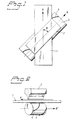
- Fig. 1
- is a view from above of one embodiment of the present invention.
- Fig. 2
- is a side view of one embodiment of a cylinder provided with ultrasonic anvils in accordance with the invention.
- The method is based on the basic concept of maintaining a constant pressure between horn and anvil and a contact surface therebetween of constant size when welding or cutting material ultrasonically. By this is meant a constant total pressure and constant pressure per unit of area. The invention reduces the risk of uneven wear, uneven energy consumption and so-called cobblestoning, i.e. a hammering motion between horn and anvil. The invention also enables material to be worked more quickly, by extending the treatment time per unit of area, which also reduces the energy consumption per unit of time.
- The invention illustrated by a preferred embodiment in the accompanying Figures is easiest described with reference to the reference signs used. Thus,
reference numeral 1 identifies a web of material in which a weld or a cut is to be made. The weld or cut is desired preferably transversely to the movement direction of theweb 1, as symbolized with the arrow A. The Fig. 1 embodiment also includes an elongatedultrasonic horn 2, the extension of which is generally indicated by the arrowB. A cylinder 3 carrying aultrasonic anvil 4 is placed parallel with theultrasonic horn 2. The rotational axis of the cylinder is referenced B'. The axes A and B define therebetween an angle β, this angle, naturally, being the same as the angle defined by A and B'. The angle β is chosen within the range 10° ≤ β ≤ 80°, or within the range 100° ≤ β ≤ 170°, preferably within the range 30° ≤ β ≤ 60° or 120° ≤ β ≤ 150° respectively. - Fig. 2 illustrates the
cylinder 3 carrying theanvil 4. Theanvil 4 has a generally helical form in the longitudinal direction of thecylinder 3, i.e. extends helically on the outer cylindrical surface of said cylinder. Analogously, theanvil surface 4 has a generally constant pitch and describes a complete screw-turn, in other words extends helically around thecylinder 3 through 360°. As before mentioned, theultrasonic horn 2 and thecylinder 3 are both positioned so that their mutually longitudinal axes will define an angle β and β' respectively in relation to the movement direction A of theweb 1. When the angle β and β' are adapted to the pitch of thehelical anvil 4 and the rotational speed of thecylinder 3 is adapted to the speed at which theweb 1 moves, the peripheral speed of thecylinder 3 will be such that the speed of theanvil 4 at the welding point will coincide essentially with the speed of theweb 1 and the ultrasonic welding process will take place at a point which moves successively along the full length of thehorn 2 and along the full length of theanvil 4 as thecylinder 3 rotates. In other words, the point of abutment between thehorn 2 and theanvil 4 will wander successively from left to right as thecylinder 3 rotates, as evident from Fig. 1. Consequently, a weld, or cut, will be formed, or made, in a direction transversely to the movement direction A of theweb 1. Theanvil 4 extends helically through 360°, i.e. theanvil 4 will constantly be in abutment with thehorn 2 at one point or another throughout one full revolution of the outer surface of thecylinder 3, therewith maintaining a contact surface of constant size between the horn and the anvil and also a constant abutment pressure force. This embodiment also provides a desired spacing between transversal welds or cuts, preferably by selection of acylinder 3 whose outer surface is adapted to this spacing. According to another embodiment of the invention, theanvil 4 has a similar helical configuration although in the case the helix extends only through part of one revolution of the outer surface of the cylinder. The angle β and β', however, are such that when a is the distance travelled by theweb 1 in the movement direction A of the web during the same time as the weld, or cut, is made across the web with a width b, then Tan β = b/a. Naturally, Tan β' will also equal b/a. - It will be understood that the invention is not restricted to the aforedescribed and illustrated exemplifying embodiment thereof and that other embodiments are conceivable within the scope of the inventive concept. For instance, the angle β and β' can be chosen to produce welds or cuts which extend essentially obliquely across the web. The
anvil 4 on thecylinder 3 may also be given a pitch which is not constant, so as the obtain non-linear welds or cuts. It is also conceivable to use acylinder 3 that has more than one helically extendinganvil 4, particularly when desiring a small spacing between the welds or cuts. In this way, a low cylinder-rotational speed is also obtained. Combinations of welds, optionally of different configurations, can also be obtained by providing thecylinder 3 with more anvil surfaces 4.
Claims (6)
- An apparatus for ultrasonically welding or cutting a moving web (1) of material generally transversely to its direction of movement (A), comprising at least one elongated ultrasonic horn (2) and at least one anvil (4) corresponding to said horn, the web being moved between the at least one horn and the at least one corresponding anvil, characterized in that the at least one elongated ultrasonic horn (2) is placed at an oblique angle (β) to said direction of web movement (A), and in that the corresponding at least one anvil (4) is arranged on a rotatable cylinder (3) whose rotational axis (B') is generally parallel with the longitudinal axis (B) of the horn (2).
- An apparatus according to Claim 1, characterized in that the at least one anvil (4) is extended helically along the cylinder (3) with a constant pitch in the direction of the rotational axis (B') of the cylinder.
- An apparatus according to Claim 1, characterized in that the at least one anvil (4) is extended helically along the cylinder (3) with an inconstant pitch in the direction of the rotational axis (B') of the cylinder.
- A method of ultrasonically welding or cutting a web (1) moving between at least one elongated ultrasonic horn (2) and at least one corresponding anvil (4) generally transversely to its direction of movement (A), each elongated ultrasonic horn (2) being placed at an oblique angle (β) to said direction of web movement (A) and each anvil (4) being arranged on a rotatable cylinder (3) whose rotational axis (B') is generally parallel with the longitudinal axis (B) of the horn (2), characterized by adapting the rotational speed of the cylinder (3) to the speed of the web (1), so that the peripheral speed of the cylinder (3) is such that the speed of the anvil (4) at the welding point coincides with the speed of the web (1).
- A method according to Claim 4, the at least one anvil extending helically along the cylinder (3), characterized by adapting the obliqueness of the horn (2) and the anvil-carrying cylinder (3) such as to form the angle (β) in relation to the movement direction (A) of the web (1) to the helical pitch of the anvil (4) so that the point of abutment between the horn (2) and the anvil (4) will move successively along the length of the horn (2) and the anvil (4) during a welding or cutting process, said welding or cutting process being effected essentially transversely to the movement direction (A) of the web (1).
- A method according to Claim 5, characterized by controlling the distance between two mutually sequential welds or cuts in said web (1) by selection of the radius of the anvil-carrying cylinder (3) and the number of anvils (4) carried thereby.
Applications Claiming Priority (3)
| Application Number | Priority Date | Filing Date | Title |
|---|---|---|---|
| SE9504424A SE505546C2 (en) | 1995-12-11 | 1995-12-11 | Method of providing a weld or clip by ultrasound |
| SE9504424 | 1995-12-11 | ||
| PCT/SE1996/001547 WO1997021535A1 (en) | 1995-12-11 | 1996-11-26 | A method of welding or cutting material ultrasonically |
Publications (2)
| Publication Number | Publication Date |
|---|---|
| EP0868288A1 EP0868288A1 (en) | 1998-10-07 |
| EP0868288B1 true EP0868288B1 (en) | 2000-01-19 |
Family
ID=20400546
Family Applications (1)
| Application Number | Title | Priority Date | Filing Date |
|---|---|---|---|
| EP96940739A Expired - Lifetime EP0868288B1 (en) | 1995-12-11 | 1996-11-26 | A method of welding or cutting material ultrasonically |
Country Status (6)
| Country | Link |
|---|---|
| US (1) | US5985065A (en) |
| EP (1) | EP0868288B1 (en) |
| JP (1) | JP4058502B2 (en) |
| DE (1) | DE69606325T2 (en) |
| SE (1) | SE505546C2 (en) |
| WO (1) | WO1997021535A1 (en) |
Families Citing this family (29)
| Publication number | Priority date | Publication date | Assignee | Title |
|---|---|---|---|---|
| US6583364B1 (en) * | 1999-08-26 | 2003-06-24 | Sony Chemicals Corp. | Ultrasonic manufacturing apparatuses, multilayer flexible wiring boards and processes for manufacturing multilayer flexible wiring boards |
| DE10026142A1 (en) | 2000-05-26 | 2001-12-13 | Basf Ag | Process and device for the continuous production of organic mono- or polyisocyanates |
| US6503238B1 (en) | 2000-06-16 | 2003-01-07 | Sca Hygiene Products Ab | Disposable liquid absorbent article with elasticizing members |
| DE10029797A1 (en) * | 2000-06-16 | 2001-12-20 | Eul & Guenther Gmbh | Method and device for producing multi-layer products and associated product |
| ES2373782T3 (en) | 2001-02-08 | 2012-02-08 | Tyco Healthcare Group Lp | ULTRASONIC SURGICAL INSTRUMENT. |
| US20040054364A1 (en) * | 2002-02-08 | 2004-03-18 | Ernest Aranyi | Ultrasonic surgical instrument |
| US20080214967A1 (en) * | 2004-02-17 | 2008-09-04 | Ernest Aranyi | Ultrasonic surgical instrument |
| FR2829961B1 (en) * | 2001-09-25 | 2006-11-10 | Clip Off | METHOD AND MACHINE FOR WELDING TWO ULTRASOUND FILMS |
| DE10210075B4 (en) * | 2002-03-08 | 2008-04-30 | Stapla Ultraschall-Technik Gmbh | Device for sealing and separating a pipe section |
| US7204899B2 (en) * | 2003-04-30 | 2007-04-17 | Kimberly-Clark Worldwide, Inc. | Apparatus and method for mechanically bonding and cutting an article |
| JP4487542B2 (en) * | 2003-11-27 | 2010-06-23 | Tdk株式会社 | Conductor paste for multilayer ceramic electronic component and method for manufacturing multilayer unit for multilayer ceramic electronic component |
| JP4662298B2 (en) * | 2003-12-15 | 2011-03-30 | Tdk株式会社 | Dielectric paste for spacer layer of multilayer ceramic electronic components |
| JP4487596B2 (en) * | 2004-02-27 | 2010-06-23 | Tdk株式会社 | Method for manufacturing multilayer unit for multilayer ceramic electronic component |
| JP4487595B2 (en) * | 2004-02-27 | 2010-06-23 | Tdk株式会社 | Method for manufacturing multilayer unit for multilayer ceramic electronic component |
| JP4412013B2 (en) * | 2004-03-16 | 2010-02-10 | Tdk株式会社 | Dielectric paste for multilayer ceramic electronic component and method for producing multilayer unit for multilayer ceramic electronic component |
| DE102004022313B3 (en) * | 2004-05-04 | 2005-10-20 | Stapla Ultraschalltechnik Gmbh | Apparatus and method for fluid-tight sealing welding of a pipe section |
| GB2433465B (en) * | 2005-12-20 | 2011-06-08 | Bm Polyco Ltd | Apparatus for manufacture of an article from non woven sheets |
| GB2444039A (en) * | 2006-11-27 | 2008-05-28 | Mars Inc | Ultrasonic welding with rotating anvil |
| GB2484267A (en) * | 2010-10-01 | 2012-04-11 | Concepts For Success | Ultrasonic welding using helical anvil |
| JP5728214B2 (en) * | 2010-12-10 | 2015-06-03 | 花王株式会社 | Ultrasonic bonding apparatus, web bonding method using the same, and manufacturing method of pants-type wearing articles using the same |
| JP2012145490A (en) * | 2011-01-13 | 2012-08-02 | Sankei Engineering:Kk | Manufacturing method of inspection probe |
| DE102012002061A1 (en) * | 2012-02-03 | 2013-08-08 | Emitec Gesellschaft Für Emissionstechnologie Mbh | Dosing valve for freeze-risk additives |
| GB201211577D0 (en) * | 2012-06-29 | 2012-08-15 | Concepts For Success C4S | Method and apparatus for the manufacturing of sandwich structures with free flowing materials and such structures |
| ES2408805B1 (en) * | 2013-02-28 | 2014-04-07 | Hostel Drap, S.L. | Cutting procedure for obtaining textile parts in continuous manufacturing processes |
| ITTO20130206A1 (en) * | 2013-03-18 | 2014-09-19 | Cavanna Spa | ULTRASONIC WELDING DEVICE |
| US8961718B2 (en) * | 2013-05-08 | 2015-02-24 | Shenzhen China Star Optoelectronics Technology Co., Ltd | Apparatus and method for laminating anisotropic conductive film on flat display panel |
| JP7359341B2 (en) | 2020-03-13 | 2023-10-11 | 精電舎電子工業株式会社 | Sheet material seal cutting method and sheet material seal cutting device |
| WO2022099382A1 (en) * | 2020-11-16 | 2022-05-19 | Merctech Pty Ltd | Method of manufacturing a protective gown |
| GB2606511A (en) * | 2021-03-26 | 2022-11-16 | Hs Products Ltd | Continuous production of pocketed springs |
Family Cites Families (12)
| Publication number | Priority date | Publication date | Assignee | Title |
|---|---|---|---|---|
| US3242029A (en) * | 1963-05-13 | 1966-03-22 | Kleer Vu Ind Inc | Ultrasonic sealer for sealing plastics |
| US3993532A (en) * | 1974-11-11 | 1976-11-23 | Consolidated Engravers Corporation | Ultrasonic sealing pattern roll |
| US3939033A (en) * | 1974-12-16 | 1976-02-17 | Branson Ultrasonics Corporation | Ultrasonic welding and cutting apparatus |
| CH639593A5 (en) * | 1980-12-10 | 1983-11-30 | Branson Sonic Power Sa | Device for ultrasonically welding the two ends of a band made of thermoplastic material |
| US4531999A (en) * | 1982-01-26 | 1985-07-30 | The Procter & Gamble Company | Dynamic laminating method and apparatus for ultrasonically bonding juxtaposed webs |
| US4430148A (en) * | 1982-04-27 | 1984-02-07 | The Procter & Gamble Company | Ultrasonic bonding apparatus |
| US4711693A (en) * | 1986-07-07 | 1987-12-08 | Branson Ultrasonics Corp. | Anvil for ultrasonic slitting apparatus |
| US4747895A (en) * | 1986-08-20 | 1988-05-31 | American White Cross Laboratories, Inc. | Continuous ultrasonic perforating system and method |
| US4690722A (en) * | 1986-10-24 | 1987-09-01 | Branson Ultrasonics Corporation | Ultrasonic apparatus for joining and severing sheet material |
| ATE83435T1 (en) * | 1989-04-05 | 1993-01-15 | Sm Engineering Ag | METHOD AND DEVICE FOR ULTRASONIC WELDING OF RIBBONS. |
| US5198056A (en) * | 1989-04-05 | 1993-03-30 | Sm Engineering Ag | Method and device for ultrasonic welding or printing ribbons |
| DE19511698C1 (en) * | 1995-03-30 | 1996-08-22 | Schober Werkzeug & Maschbau | Device for connecting a sealing film to a material web |
-
1995
- 1995-12-11 SE SE9504424A patent/SE505546C2/en not_active IP Right Cessation
-
1996
- 1996-11-26 EP EP96940739A patent/EP0868288B1/en not_active Expired - Lifetime
- 1996-11-26 US US09/091,189 patent/US5985065A/en not_active Expired - Lifetime
- 1996-11-26 JP JP52197397A patent/JP4058502B2/en not_active Expired - Fee Related
- 1996-11-26 DE DE69606325T patent/DE69606325T2/en not_active Expired - Fee Related
- 1996-11-26 WO PCT/SE1996/001547 patent/WO1997021535A1/en active IP Right Grant
Also Published As
| Publication number | Publication date |
|---|---|
| JP2000502005A (en) | 2000-02-22 |
| SE9504424D0 (en) | 1995-12-11 |
| JP4058502B2 (en) | 2008-03-12 |
| SE505546C2 (en) | 1997-09-15 |
| WO1997021535A1 (en) | 1997-06-19 |
| US5985065A (en) | 1999-11-16 |
| DE69606325T2 (en) | 2000-08-24 |
| DE69606325D1 (en) | 2000-02-24 |
| EP0868288A1 (en) | 1998-10-07 |
| SE9504424L (en) | 1997-06-12 |
Similar Documents
| Publication | Publication Date | Title |
|---|---|---|
| EP0868288B1 (en) | A method of welding or cutting material ultrasonically | |
| EP0873235B1 (en) | Ultrasonic system and method | |
| US3939033A (en) | Ultrasonic welding and cutting apparatus | |
| US3419447A (en) | Method and apparatus for bonding together two thermoplastic sheets by ultrasonic energy | |
| CA1198349A (en) | Ultrasonic bonding apparatus | |
| AU706086B2 (en) | Rotary sealing system | |
| EP2094470B1 (en) | Rotary ultrasonic sealing | |
| CA2259494C (en) | Stacked rotary acoustic horn | |
| CA1303950C (en) | Apparatus and method for ultrasonic bonding of a moving web | |
| KR19990071855A (en) | Embossing and laminating machines and methods with contact area dispersed cylinders | |
| JP2005509545A (en) | Ultrasonic coupling device for multilayer material web | |
| CN114390969A (en) | Apparatus and method for producing aggregated or aggregatable material | |
| US20120186719A1 (en) | Method For Performing An Ultrasonic Welding Process On At Least One Web | |
| GB2283700B (en) | A method and an arrangement for ultrasonic welding | |
| EP0564189B1 (en) | A method for welding a packing band of thermoplastic resin, and a welded band | |
| JP3204194B2 (en) | Ultrasonic welding fusing equipment | |
| EP0141667A2 (en) | Methods and apparatus for joining superimposed laminar workpieces | |
| CN113795226B (en) | Welding system and welding method for mesh | |
| JPH03251285A (en) | Manufacture of cushion material | |
| DE20314762U1 (en) | Sonotrode for transmitting ultrasound, comprises an inlet contact surface, an outlet contact surface, and lateral and longitudinal oscillators | |
| JPH0412837A (en) | Laminated sheet, manufacture of laminated sheet and apparatus for manufacturing laminated sheet |
Legal Events
| Date | Code | Title | Description |
|---|---|---|---|
| PUAI | Public reference made under article 153(3) epc to a published international application that has entered the european phase |
Free format text: ORIGINAL CODE: 0009012 |
|
| 17P | Request for examination filed |
Effective date: 19980522 |
|
| AK | Designated contracting states |
Kind code of ref document: A1 Designated state(s): DE FR GB IT NL |
|
| GRAG | Despatch of communication of intention to grant |
Free format text: ORIGINAL CODE: EPIDOS AGRA |
|
| 17Q | First examination report despatched |
Effective date: 19990121 |
|
| GRAG | Despatch of communication of intention to grant |
Free format text: ORIGINAL CODE: EPIDOS AGRA |
|
| GRAH | Despatch of communication of intention to grant a patent |
Free format text: ORIGINAL CODE: EPIDOS IGRA |
|
| RAP1 | Party data changed (applicant data changed or rights of an application transferred) |
Owner name: SCA HYGIENE PRODUCTS AB |
|
| GRAH | Despatch of communication of intention to grant a patent |
Free format text: ORIGINAL CODE: EPIDOS IGRA |
|
| GRAA | (expected) grant |
Free format text: ORIGINAL CODE: 0009210 |
|
| AK | Designated contracting states |
Kind code of ref document: B1 Designated state(s): DE FR GB IT NL |
|
| REF | Corresponds to: |
Ref document number: 69606325 Country of ref document: DE Date of ref document: 20000224 |
|
| ITF | It: translation for a ep patent filed |
Owner name: BARZANO' E ZANARDO ROMA S.P.A. |
|
| ET | Fr: translation filed | ||
| PLBE | No opposition filed within time limit |
Free format text: ORIGINAL CODE: 0009261 |
|
| STAA | Information on the status of an ep patent application or granted ep patent |
Free format text: STATUS: NO OPPOSITION FILED WITHIN TIME LIMIT |
|
| 26N | No opposition filed | ||
| REG | Reference to a national code |
Ref country code: GB Ref legal event code: IF02 |
|
| PGFP | Annual fee paid to national office [announced via postgrant information from national office to epo] |
Ref country code: FR Payment date: 20041029 Year of fee payment: 9 |
|
| PGFP | Annual fee paid to national office [announced via postgrant information from national office to epo] |
Ref country code: GB Payment date: 20041103 Year of fee payment: 9 |
|
| PGFP | Annual fee paid to national office [announced via postgrant information from national office to epo] |
Ref country code: NL Payment date: 20041112 Year of fee payment: 9 |
|
| PG25 | Lapsed in a contracting state [announced via postgrant information from national office to epo] |
Ref country code: GB Free format text: LAPSE BECAUSE OF NON-PAYMENT OF DUE FEES Effective date: 20051126 |
|
| PG25 | Lapsed in a contracting state [announced via postgrant information from national office to epo] |
Ref country code: NL Free format text: LAPSE BECAUSE OF NON-PAYMENT OF DUE FEES Effective date: 20060601 |
|
| GBPC | Gb: european patent ceased through non-payment of renewal fee |
Effective date: 20051126 |
|
| PG25 | Lapsed in a contracting state [announced via postgrant information from national office to epo] |
Ref country code: FR Free format text: LAPSE BECAUSE OF NON-PAYMENT OF DUE FEES Effective date: 20060731 |
|
| NLV4 | Nl: lapsed or anulled due to non-payment of the annual fee |
Effective date: 20060601 |
|
| REG | Reference to a national code |
Ref country code: FR Ref legal event code: ST Effective date: 20060731 |
|
| PGFP | Annual fee paid to national office [announced via postgrant information from national office to epo] |
Ref country code: DE Payment date: 20081124 Year of fee payment: 13 |
|
| PGFP | Annual fee paid to national office [announced via postgrant information from national office to epo] |
Ref country code: IT Payment date: 20081125 Year of fee payment: 13 |
|
| PG25 | Lapsed in a contracting state [announced via postgrant information from national office to epo] |
Ref country code: DE Free format text: LAPSE BECAUSE OF NON-PAYMENT OF DUE FEES Effective date: 20100601 |
|
| PG25 | Lapsed in a contracting state [announced via postgrant information from national office to epo] |
Ref country code: IT Free format text: LAPSE BECAUSE OF NON-PAYMENT OF DUE FEES Effective date: 20091126 |