EP0867656B1 - Pressure gas cartridge - Google Patents
Pressure gas cartridge Download PDFInfo
- Publication number
- EP0867656B1 EP0867656B1 EP97810181A EP97810181A EP0867656B1 EP 0867656 B1 EP0867656 B1 EP 0867656B1 EP 97810181 A EP97810181 A EP 97810181A EP 97810181 A EP97810181 A EP 97810181A EP 0867656 B1 EP0867656 B1 EP 0867656B1
- Authority
- EP
- European Patent Office
- Prior art keywords
- valve
- hollow body
- longitudinal bore
- valve pin
- pressure gas
- Prior art date
- Legal status (The legal status is an assumption and is not a legal conclusion. Google has not performed a legal analysis and makes no representation as to the accuracy of the status listed.)
- Expired - Lifetime
Links
Images

Classifications
-
- F—MECHANICAL ENGINEERING; LIGHTING; HEATING; WEAPONS; BLASTING
- F17—STORING OR DISTRIBUTING GASES OR LIQUIDS
- F17C—VESSELS FOR CONTAINING OR STORING COMPRESSED, LIQUEFIED OR SOLIDIFIED GASES; FIXED-CAPACITY GAS-HOLDERS; FILLING VESSELS WITH, OR DISCHARGING FROM VESSELS, COMPRESSED, LIQUEFIED, OR SOLIDIFIED GASES
- F17C13/00—Details of vessels or of the filling or discharging of vessels
- F17C13/04—Arrangement or mounting of valves
-
- F—MECHANICAL ENGINEERING; LIGHTING; HEATING; WEAPONS; BLASTING
- F17—STORING OR DISTRIBUTING GASES OR LIQUIDS
- F17C—VESSELS FOR CONTAINING OR STORING COMPRESSED, LIQUEFIED OR SOLIDIFIED GASES; FIXED-CAPACITY GAS-HOLDERS; FILLING VESSELS WITH, OR DISCHARGING FROM VESSELS, COMPRESSED, LIQUEFIED, OR SOLIDIFIED GASES
- F17C2205/00—Vessel construction, in particular mounting arrangements, attachments or identifications means
- F17C2205/03—Fluid connections, filters, valves, closure means or other attachments
- F17C2205/0302—Fittings, valves, filters, or components in connection with the gas storage device
- F17C2205/0323—Valves
-
- F—MECHANICAL ENGINEERING; LIGHTING; HEATING; WEAPONS; BLASTING
- F17—STORING OR DISTRIBUTING GASES OR LIQUIDS
- F17C—VESSELS FOR CONTAINING OR STORING COMPRESSED, LIQUEFIED OR SOLIDIFIED GASES; FIXED-CAPACITY GAS-HOLDERS; FILLING VESSELS WITH, OR DISCHARGING FROM VESSELS, COMPRESSED, LIQUEFIED, OR SOLIDIFIED GASES
- F17C2270/00—Applications
- F17C2270/07—Applications for household use
- F17C2270/0736—Capsules, e.g. CO2
Definitions
- the present invention relates to a compressed gas capsule according to the preamble of claim 1.
- Such compressed gas capsules for example, with CO2 as compressed gas are filled, for example, for gas filling of creamers, for inflating bicycle tires or for making carbonated drinks be used.
- Drusolcheckgaskapsetn Such Drusolcheckgaskapsetn are known. So shows, for example CH-A 511 396, which as the next State of the art eye becomes, a compressed gas capsule consisting of a hollow body and a used therein check valve.
- the check valve has a Valve body, which is provided with a longitudinal bore, in which a Valve pin is guided displaceably.
- the valve pin In filled with compressed gas state of Pressurized gas capsule, the valve pin is pressed into a front end position, in which it is pressed against a sealing lip, the compressed gas capsule is sealed.
- the valve pin pushed inwards, with tongues on the outside at the edge of the valve pin are provided, which are bent outwards, thereby avoiding is that the valve pin can be pressed too far inward.
- pressure gas capsules which after the Filling be closed by a membrane, which when opening must be punctured. These compressed gas capsules can only once be used and then thrown away and also disposed of become.
- the object of the present invention is now a To create compressed gas capsule, which several times after emptying in easier Can be refilled without having to replace parts, and in which the functionality is full even after multiple use is guaranteed.
- the stops are in the form of projections formed, which integrally formed on the existing of a plastic valve body are.
- the valve body can be produced in one operation be, the valve pin is pressed into the valve body, wherein the projections elastically recede and after inserting the valve pin go back to its original shape.
- the hollow body consists of a metallic Material, wherein at least its surface is corrosion resistant is. This ensures in particular in the multiple reusability, that the condition of the compressed gas capsule also in aesthetic terms remains optimal.
- a further advantageous embodiment of the compressed gas capsule is in that the connection between the hollow body and the valve body takes place in such a way that that provided between valve body and valve pin sealing point within of the hollow body is arranged so that damage to the valve body outside the hollow body no effect on the tightness of Have compressed gas capsule.
- the compressed gas capsule 1 is shown, which consists of a with a Opening 2 provided hollow body 3 consists.
- This hollow body 3 is made made of a metallic material, wherein at least the surface corrosion resistant is. Inserted into the opening 2 is the check valve. 4
- This check valve 4 consists of a valve body 5, with a continuous longitudinal bore 6 is provided, in which a constriction 7 is provided.
- the constriction 7 is at its end, which is against the Hollow body is directed towards, designed as a truncated cone 8, which is against the Hollow body 3 expands out.
- valve pin 9 In the longitudinal bore 6 of the valve body 5, a valve pin 9 is inserted.
- This valve pin 9 has a thickening 10, as against the inside of the hollow body 3 is widening truncated cone 11 is formed.
- the truncated cone 11 of the valve pin 9 and the truncated cone 8 of the valve body 5 are sealed in the closed state of the check valve 4 pressed on each other. This is done automatically by the overpressure of the in the Compressed gas capsule 1 filled CO2 gas. In this state, as shown in Fig. 1 is shown, the valve pin 9 is in its first end position.
- the protruding into the hollow body 3 end portion of the valve body 5 has three projections projecting radially inwards into the longitudinal bore 6 12, wherein in the illustration according to FIG. 1, only one is visible.
- the valve body 5 is made of a plastic, the projections 12 are formed directly on the valve body 5. Prevent these projections 12 that the valve pin 9 against the inside of the hollow body 3 out of the Can move out valve body 5. Through these projections 12, as a stop act, the second inner end position of the valve pin 9 in the longitudinal bore 6 of the valve body 5 fixed.
- valve pin 9 When inserting the valve pin 9 in the valve body 5 is the Valve pin 9 pressed over the projections 12, and since the valve body 5 made made of a plastic which has a certain elasticity, soft the projections 12 together with the lower edge of the valve body 5 elastic back until the thickening 10 of the valve pin 9, these projections 12th has run over. Thereafter, this area of the valve body 5 takes the original Form, the valve pin 9 is trapped.
- the check valve 4 is inserted into the opening 2 of the hollow body 3.
- a groove 13 is pressed over the entire circumference, whereby the desired connection is achieved.
- This groove 13 comes in one Area of the valve body 5 to lie, from the inside of the hollow body 3 seen from outside the constriction 7 is located. This is especially the sealing area of the check valve 4 optimally protected, a Damage of the over the hollow body 3 projecting portion of the valve body 5, for example by dropping, has no influence on the sealing point, the compressed gas can not escape.
- the valve pin 9 has on to the widening truncated cone 11th adjoining end region on a flange-shaped thickening 14. These flange-shaped thickening 14 comes on three flats 15 to the plant, the along the displacement of the valve pin 9 distributed over the circumference and running parallel in the longitudinal bore 6 are mounted. In the sectional view 1, only one of these flats 15 is visible.
- Valve pin 9 can extend inwards.
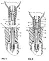
- FIG. 4 shows a detail of a device 17 in which the receiving part 18 is arranged for the compressed gas capsule.
- This device 17 for example, a cream blower, a pumping device for a bicycle tube or a device for carbonating liquids.
- the Receiving part 18 has an opening 19, in which in a known manner Hollow pin 20 is inserted, which has a sealing jacket 21 on the inside. To the projecting into the opening 19 portion of the hollow pin 20th a sealing ring 22 is placed.
- the receiving part 18 can now be the compressed gas capsule 1 with the Fit non-return valve 4.
- the valve pin 9 is in its first End position, that is, the hollow body 3 is tightly closed, the interior the hollow body 3 is filled with the pressurized gas.
- the plant for refilling the inventive pressure gas capsules 1 could comprise a receiving part which corresponds to the receiving part 18 Fig. 4 and 5 corresponds, wherein only instead of a sealing jacket 21 another embodiment of the hollow bolt 20 would have to be done.
- the Gas cylinder 1 could thus in the same way in the receiving part of a Refilling system are used, as shown in FIG. 5 is shown, the hollow pin would also push back the valve pin, the gas could flow in the opposite direction and the compressed gas capsule fill up.
- the valve pin 9 by the pressure of the gas in the Pressurized gas capsule would immediately pressed into the sealing position.
- the receiving part 18 according to 4 and 5 to change such that the sealing ring 22 is not around the Hollow pin 21 is placed, but in a corresponding groove in the opening 19 could be inserted, whereby the seal between receiving part 18th and valve body would take place on the outside thereof.
Landscapes
- Engineering & Computer Science (AREA)
- Mechanical Engineering (AREA)
- General Engineering & Computer Science (AREA)
- Check Valves (AREA)
- Filling Or Discharging Of Gas Storage Vessels (AREA)
- Medicinal Preparation (AREA)
- Manufacturing Of Micro-Capsules (AREA)
- Steroid Compounds (AREA)
Abstract
Description
Die vorliegende Erfindung bezieht sich auf eine Druckgaskapsel
gemäss dem Oberbegriff des Patentanspruchs 1.The present invention relates to a compressed gas capsule
according to the preamble of
Derartige Druckgaskapseln, die beispielsweise mit CO2 als Druckgas gefüllt sind, können beispielsweise zur Gasbefüllung von Rahmbläsern, zum Aufpumpen von Veloreifen oder zum Herstellen von karbonisierten Getränken verwendet werden.Such compressed gas capsules, for example, with CO2 as compressed gas are filled, for example, for gas filling of creamers, for inflating bicycle tires or for making carbonated drinks be used.
Derartige Drusolcheckgaskapsetn sind bekannt. So zeigt beispielsweise die CH-A 511 396, welche als nächsliegender Stand der Technik augesehen wird, eine Druckgaskapsel, die aus einem Hohlkörper und einem darin eingesetzten Rückschlagventil besteht. Das Rückschlagventil weist einen Ventilkörper auf, der mit einer Längsbohrung versehen ist, in welchem ein Ventilstift verschiebbar geführt ist. Im mit Druckgas gefülltem Zustand der Druckgaskapsel wird der Ventilstift in eine vordere Endlage gedrückt, in welcher er gegen eine Dichtlippe gepresst wird, die Druckgaskapsel ist dicht verschlossen. Zum Auffüllen oder Entleeren der Druckgaskapsel wird der Ventilstift nach innen gestossen, wobei aussenseitig am Rand des Ventilstifts Zungen vorgesehen sind, die nach aussen gebogen werden, wodurch vermieden wird, dass der Ventilstift zu weit nach innen gedrückt werden kann.Such Drusolcheckgaskapsetn are known. So shows, for example CH-A 511 396, which as the next State of the art eye becomes, a compressed gas capsule consisting of a hollow body and a used therein check valve. The check valve has a Valve body, which is provided with a longitudinal bore, in which a Valve pin is guided displaceably. In filled with compressed gas state of Pressurized gas capsule, the valve pin is pressed into a front end position, in which it is pressed against a sealing lip, the compressed gas capsule is sealed. For filling or emptying the compressed gas capsule is the valve pin pushed inwards, with tongues on the outside at the edge of the valve pin are provided, which are bent outwards, thereby avoiding is that the valve pin can be pressed too far inward.
Diese Druckgaskapseln können nur einmal verwendet werden, da nicht ausgeschlossen werden kann, dass der Ventilstift bei wiederholter Verwendung beschädigt wird. Insbesondere besteht die Gefahr, dass die umgebogenen Zungen abbrechen könnten. Nach der einmaligen Verwendung müssen somit diese geleerten Druckgaskapseln weggeworfen werden, was durch die Verbraucher zunehmend als Materialverschwendung beurteilt wird.These compressed gas capsules can only be used once because can not be ruled out that the valve pin with repeated use is damaged. In particular, there is a risk that the bent Tongues could break off. After the single use need Thus, these emptied compressed gas capsules are thrown away, which by the Consumers are increasingly being judged as a waste of material.
Des weiteren sind auch Druckgaskapseln bekannt, die nach dem Auffüllen durch eine Membrane verschlossen werden, welche beim Öffnen durchstochen werden muss. Auch diese Druckgaskapseln können nur einmal verwendet werden und müssen danach weggeworfen und ebenfalls entsorgt werden. Furthermore, pressure gas capsules are known, which after the Filling be closed by a membrane, which when opening must be punctured. These compressed gas capsules can only once be used and then thrown away and also disposed of become.
Die Aufgabe der vorliegenden Erfindung besteht nun darin, eine Druckgaskapsel zu schaffen, die mehrfach nach dem Entleeren in einfacher Weise wieder befüllt werden kann, ohne dass Teile ersetzt werden müssen, und bei welcher die Funktionsfähigkeit auch nach mehrfacher Verwendung voll gewährleistet ist.The object of the present invention is now a To create compressed gas capsule, which several times after emptying in easier Can be refilled without having to replace parts, and in which the functionality is full even after multiple use is guaranteed.
Erfindungsgemäss erfolgt die Lösung dieser Aufgabe durch die im
Anspruch 1 angegebenen Merkmale.According to the invention, the solution of this problem by the
Durch die Verwendung von Dichtflächen, die kegelstumpfförmig ausgebildet sind, und dadurch, dass die die innere Endlage des Ventilstiftes festlegenden Anschläge im gegen die Innenseite des Hohlkörpers liegenden Endbereich der Längsbohrung angebracht sind, wird eine Beschädigung der entsprechenden Teile auch bei mehrfacher Verwendung vermieden, wodurch ein sicheres Funktionieren gewährleistet ist.By using sealing surfaces that are frustoconical are formed, and in that the inner end position of the valve pin defining stops in against the inside of the hollow body lying End region of the longitudinal bore are attached, damage to the avoiding corresponding parts even with multiple use, which a safe functioning is ensured.
In vorteilhafter Weise sind die Anschläge in Form von Vorsprüngen ausgebildet, die an dem aus einem Kunststoff bestehenden Ventilkörper angeformt sind. Dadurch kann der Ventilkörper in einem Arbeitsgang hergestellt werden, der Ventilstift wird in den Ventilkörper eingepresst, wobei die Vorsprünge elastisch zurückweichen und nach dem Einsetzen des Ventilstiftes wieder in die ursprüngliche Form zurückgehen.Advantageously, the stops are in the form of projections formed, which integrally formed on the existing of a plastic valve body are. As a result, the valve body can be produced in one operation be, the valve pin is pressed into the valve body, wherein the projections elastically recede and after inserting the valve pin go back to its original shape.
Um eine optimale Führung des Ventilstifts während dessen Längsverschiebung zu gewährleisten, ist dieser mit einer flanschförmigen Verdickung ausgestattet, welche durch drei parallel verlaufende, über den Umfang verteilte Abflachungen in der Längsbohrung während des Verschiebens geführt ist. Dadurch wird eine sichere Funktion der Druckgaskapsel erreicht, insbesondere ist es auch möglich, die Druckgaskapsel bei der Verwendung vorerst nur teilweise zu leeren und dass trotzdem wieder eine vollständige Dichtung erreicht wird.For optimum guidance of the valve pin during its longitudinal displacement To ensure this is with a flange-shaped thickening equipped, which by three parallel, distributed over the circumference Flattened in the longitudinal bore during the move is performed. Thereby a safe function of the compressed gas capsule is achieved, in particular it also possible, the compressed gas capsule when using only partially to empty and that nevertheless a complete seal is achieved again.
In vorteilhafter Weise besteht der Hohlkörper aus einem metallischen Werkstoff, wobei mindestens dessen Oberfläche korrosionsbeständig ist. Dadurch wird insbesondere bei der mehrfachen Wiederverwendbarkeit gewährleistet, dass der Zustand der Druckgaskapsel auch in ästhetischer Hinsicht optimal bleibt.Advantageously, the hollow body consists of a metallic Material, wherein at least its surface is corrosion resistant is. This ensures in particular in the multiple reusability, that the condition of the compressed gas capsule also in aesthetic terms remains optimal.
Eine weitere vorteilhafte Ausgestaltung der Druckgaskapsel besteht darin, dass die Verbindung zwischen Hohlkörper und Ventilkörper so erfolgt, dass die zwischen Ventilkörper und Ventilstift vorgesehene Dichtstelle innerhalb des Hohlkörpers angeordnet ist, so dass Beschädigungen des Ventilkörpers ausserhalb des Hohlkörpers keine Auswirkungen auf die Dichtheit der Druckgaskapsel haben.A further advantageous embodiment of the compressed gas capsule is in that the connection between the hollow body and the valve body takes place in such a way that that provided between valve body and valve pin sealing point within of the hollow body is arranged so that damage to the valve body outside the hollow body no effect on the tightness of Have compressed gas capsule.
Eine Ausführungsform der erfindungsgemässen Druckgaskapsel wird nachfolgend anhand der beiliegenden Zeichnung beispielhaft näher erläutert.An embodiment of the inventive compressed gas capsule will be explained in more detail by way of example with reference to the accompanying drawings.
Es zeigt
In Fig. 1 ist die Druckgaskapsel 1 dargestellt, die aus einem mit einer
Öffnung 2 versehenen Hohlkörper 3 besteht. Dieser Hohlkörper 3 ist aus
einem metallischen Werkstoff gefertigt, wobei zumindest die Oberfläche korrosionsbeständig
ist. In die Öffnung 2 eingesetzt ist das Rückschlagventil 4.In Fig. 1, the compressed
Dieses Rückschlagventil 4 besteht aus einem Ventilkörper 5, der mit
einer durchgehenden Längsbohrung 6 versehen ist, in welcher eine Verengung
7 vorgesehen ist. Die Verengung 7 ist an ihrem Endbereich, der gegen den
Hohlkörper hin gerichtet ist, als Kegelstumpf 8 ausgebildet, der sich gegen den
Hohlkörper 3 hin erweitert.This
In die Längsbohrung 6 des Ventilkörpers 5 ist ein Ventilstift 9 eingesetzt.
Dieser Ventilstift 9 weist eine Verdickung 10 auf, die als gegen die Innenseite
des Hohlkörpers 3 sich erweiternder Kegelstumpf 11 ausgebildet ist.
Der Kegelstumpf 11 des Ventilstiftes 9 und der Kegelstumpf 8 des Ventilkörpers
5 werden im geschlossenen Zustand des Rückschlagventils 4 dichtend
aufeinander gedrückt. Dies erfolgt selbsttätig durch den Überdruck des in die
Druckgaskapsel 1 eingefüllten CO2-Gases. In diesem Zustand, wie er in Fig. 1
dargestellt ist, befindet sich der Ventilstift 9 in seiner ersten Endlage.In the
Der in den Hohlkörper 3 hineinragende Endbereich des Ventilkörpers
5 weist drei radial nach innen in die Längsbohrung 6 vorstehende Vorsprünge
12 auf, wobei in der Darstellung gemäss Fig. 1 nur einer ersichtlich ist.The protruding into the
Der Ventilkörper 5 ist aus einem Kunststoff gefertigt, die Vorsprünge
12 sind direkt am Ventilkörper 5 angeformt. Diese Vorsprünge 12 verhindern,
dass der Ventilstift 9 gegen die Innenseite des Hohlkörpers 3 hin aus dem
Ventilkörper 5 herausfahren kann. Durch diese Vorsprünge 12, die als Anschlag
wirken, wird die zweite innere Endlage des Ventilstiftes 9 in der Längsbohrung
6 des Ventilkörpers 5 festgelegt.The
Beim Einsetzen des Ventilstiftes 9 in den Ventilkörper 5 wird der
Ventilstift 9 über die Vorsprünge 12 gepresst, und da der Ventilkörper 5 aus
einem Kunststoff hergestellt ist, der eine gewisse Elastizität aufweist, weichen
die Vorsprünge 12 zusammen mit dem unteren Rand des Ventilkörpers 5 elastisch
zurück, bis die Verdickung 10 des Ventilstiftes 9 diese Vorsprünge 12
überfahren hat. Danach nimmt dieser Bereich des Ventilkörpers 5 die ursprüngliche
Form ein, der Ventilstift 9 ist gefangen.When inserting the
Zum Verbinden des Rückschlagventils 4 mit dem Hohlkörper 3 wird
das Rückschlagventil 4 in die Öffnung 2 des Hohlkörpers 3 eingesetzt. In den
Hohlkörper 3 wird über den gesamten Umfang eine Rille 13 eingepresst, wodurch
die gewünschte Verbindung erreicht wird. Diese Rille 13 kommt in einen
Bereich des Ventilkörpers 5 zu liegen, der von der Innenseite des Hohlkörpers
3 aus gesehen ausserhalb der Verengung 7 liegt. Damit ist insbesondere der
dichtende Bereich des Rückschlagventils 4 in optimaler Weise geschützt, eine
Beschädigung des über den Hohlkörper 3 vorstehenden Bereichs des Ventilkörpers
5, beispielsweise durch fallen lassen, hat keinen Einfluss auf die Dichtstelle,
das komprimierte Gas kann nicht entweichen.To connect the
Der Ventilstift 9 weist am an den sich erweiternden Kegelstumpf 11
anschliessenden Endbereich eine flanschförmige Verdickung 14 auf. Diese
flanschförmige Verdickung 14 kommt auf drei Abflachungen 15 zur Anlage, die
entlang des Verschiebeweges des Ventilstiftes 9 über den Umfang verteilt und
parallel verlaufend in der Längsbohrung 6 angebracht sind. In der Schnittdarstellung
gemäss Fig. 1 ist lediglich eine dieser Abflachungen 15 sichtbar.The
In der Draufsicht von der Innenseite des Hohlkörpers 3 her auf das
Rückschlagventil 4, dargestellt in Fig. 2, sind die drei Vorsprünge 12 ersichtlich,
die verhindern, dass der in der Längsbohrung 6 verschiebbar gelagerte
Ventilstift 9 nach innen ausfahren kann.In the plan view from the inside of the
In der Schnittdarstellung gemäss Fig. 3 sind die drei über den Umfang
der Längsbohrung 6 verteilten Abflachungen 15 ersichtlich. Die
flanschförmige Verdickung 14 (Fig. 1) des Ventilstiftes 9 liegt mit geringem
Spiel an diesen Abflachungen 15 an. Dadurch wird gewährleistet, dass der
Ventilstift 9 in der zentralen Achse der Längsbohrung 6 gehalten wird, das ein-
bzw. ausströmende Gas findet den Durchlass in den zwischen den Abflachungen
15 verbleibenden spaltförmigen Öffnungen 16, wodurch eine optimale
Funktion dieses Rückschlagventils erreicht wird. In the sectional view according to FIG. 3, the three are over the circumference
the
In Fig. 4 ist ein Ausschnitt einer Einrichtung 17 gezeigt, in welcher
der Aufnahmeteil 18 für die Druckgaskapsel angeordnet ist. Diese Einrichtung
17 kann beispielsweise ein Rahmbläser, eine Pumpvorrichtung für einen Veloschlauch
oder eine Einrichtung zum Karbonisieren von Flüssigkeiten sein. Der
Aufnahmeteil 18 weist eine Öffnung 19 auf, in welche in bekannter Weise ein
Hohlbolzen 20 eingesetzt ist, der innenseitig einen Dichtungsmantel 21 aufweist.
Um den in die Öffnung 19 hineinragenden Bereich des Hohlbolzens 20
ist ein Dichtungsring 22 gelegt.FIG. 4 shows a detail of a
In den Aufnahmeteil 18 lässt sich nun die Druckgaskapsel 1 mit dem
Rückschlagventil 4 aufsetzen. Vor dem Aufsetzen der Druckgaskapsel 1, wie
dies in Fig. 4 dargestellt ist, befindet sich der Ventilbolzen 9 in seiner ersten
Endlage, das heisst der Hohlkörper 3 ist dicht abgeschlossen, der Innenraum
des Hohlkörpers 3 ist mit dem Druckgas gefüllt.In the receiving
Im aufgesetzten Zustand des Druckgasbehälters 1 auf den Aufnahmeteil
18 der Einrichtung 17 ist der Hohlbolzen 20 in die Längsbohrung 6 des
Ventilkörpers 5 eingedrungen, der Dichtungsring 22 dichtet diese Verbindungsstelle
vollständig ab, wie dies in Fig. 5 dargestellt ist. Der Ventilstift 9
wird durch den Hohlbolzen 20 zurückgedrückt, der dichte Verschluss zwischen
Kegelstumpf 8 der Längsbohrung und Kegelstumpf 11 des Ventilstiftes wird
geöffnet, das in der Druckgaskapsel 1 unter Überdruck stehende Gas kann
ausströmen und durch den Hohlbolzen 20, der hierzu an seiner Mündung mit
schlitzförmigen Ausnehmungen 23 ausgestattet ist, in die vorgesehene Einrichtung
17 eingeleitet werden.In the attached state of the compressed
Die Anlage zur Wiederbefüllung der erfindungsgemässen Druckgaskapseln
1 könnte einen Aufnahmeteil umfassen, der dem Aufnahmeteil 18 gemäss
Fig. 4 und 5 entspricht, wobei lediglich anstelle eines Dichtungsmantels
21 eine andere Ausgestaltung des Hohlbolzens 20 zu erfolgen hätte. Der
Druckgasbehälter 1 könnte somit in gleicher Weise in den Aufnahmeteil einer
Wiederbefüllungsanlage eingesetzt werden, wie dies im wesentlichen in Fig. 5
dargestellt ist, der Hohlbolzen würde den Ventilstift ebenfalls zurück drücken,
das Gas könnte in umgekehrter Richtung fliessen und die Druckgaskapsel
auffüllen. Beim Abnehmen der Druckgaskapsel 1 von der Wiederbefüllungsanlage
hätte zur Folge, dass der Ventilstift 9 durch den Druck des Gases in der
Druckgaskapsel sofort in die dichtende Position gedrückt würde.The plant for refilling the inventive
Selbstverständlich wäre es auch denkbar, den Aufnahmeteil 18 gemäss
Fig. 4 und 5 derart zu ändern, dass der Dichtungsring 22 nicht um den
Hohlbolzen 21 gelegt wird, sondern in eine entsprechende Nut in der Öffnung
19 eingelegt werden könnte, wodurch die Dichtung zwischen Aufnahmeteil 18
und Ventilkörper an dessen Aussenseite erfolgen würde.Of course, it would also be conceivable, the receiving
Mit dieser erfindungsgemässen Druckgaskapsel wird eine sichere Funktion gewährleistet, auch nach mehrmaliger Verwendung und Wiederbefüllung, das hochwertige Material muss nicht nach einmaligem Gebrauch bereits weggeworfen bzw. entsorgt werden.With this novel compressed gas capsule is a safe Ensures function, even after repeated use and refilling, The high quality material does not have to be used even after one use be discarded or disposed of.
Claims (7)
- Pressure gas cartridge (1), comprising a hollow body (3), provided with an orifice (2), and a check valve (4) closing the orifice (2), which valve consists of a valve body (5) provided with a longitudinal bore (6), which valve body is connected in a tight way with the hollow body (3), and a valve pin (9) therein displaceably guided along the longitudinal bore (6), the valve pin (9) having a swelling (10) directed toward the interior of the hollow body (3), which swelling co-operates in a first end position of the valve pin (9) in the longitudinal bore (6) with a constriction (7) that is disposed in the longitudinal bore (6) of the valve body (5), while a second inner end position is established by a stop, and the swelling (10) of the valve pin (9) being designed as a frustum (11) expanding toward the interior of the hollow body (3), and the constriction (7) being designed as frustum (8) corresponding therewith, characterised in that the stop establishing the second inner end position of the valve pin (9) in the longitudinal bore (6) consists of at least one projection (12) protruding radially inwardly.
- Pressure gas cartridge (1) according to claim 1, characterised in that the at least one projection (12) has a rounded shape in longitudinal axial direction of the longitudinal bore (6).
- Pressure gas cartridge (1) according to claim 1 or 2, characterised in that three projections (12) are provided, which are disposed distributed over the circumference of the longitudinal bore (6) in the end region directed toward the interior of the hollow body (3), in that the valve body (5) is composed of a plastic and the projections (12) are formed on the valve body (5).
- Pressure gas cartridge (1) according to one of the claims 1 to 3, characterised in that the valve pin (9) is provided with a flange-shaped swelling (14) in the region adjacent the expanding frustum (10), and in that in the longitudinal bore (6) at least three flat portions (15) are provided, running parallel, distributed over the circumference, along which portions the valve pin (9) with the flange-shaped swelling (14) is guided during displacement.
- Pressure gas cartridge (1) according to one of the claims 1 to 4, characterised in that the valve pin (9) is made of a metallic material which is corrosion-resistant.
- Pressure gas cartridge (1) according to one of the claims 1 to 5, characterised in that the hollow body (3) is made of a metallic material, at least its surface being corrosion-resistant.
- Pressure gas cartridge (1) according to one of the claims 1 to 6, characterised in that the hollow body (3) has a bottle-like shape provided with a neck, in that the valve body (5) is inserted into the neck of the hollow body so far and the junction between hollow body (3) and valve body (5) is disposed such that the constriction (7) with the frustum (8) is within the junction in the inside region of the hollow body (3).
Priority Applications (3)
| Application Number | Priority Date | Filing Date | Title |
|---|---|---|---|
| DE59712528T DE59712528D1 (en) | 1997-03-26 | 1997-03-26 | Pressure gas capsule |
| AT97810181T ATE313757T1 (en) | 1997-03-26 | 1997-03-26 | COMPRESSED GAS CAPSULE |
| EP97810181A EP0867656B8 (en) | 1997-03-26 | 1997-03-26 | Pressure gas cartridge |
Applications Claiming Priority (1)
| Application Number | Priority Date | Filing Date | Title |
|---|---|---|---|
| EP97810181A EP0867656B8 (en) | 1997-03-26 | 1997-03-26 | Pressure gas cartridge |
Publications (3)
| Publication Number | Publication Date |
|---|---|
| EP0867656A1 EP0867656A1 (en) | 1998-09-30 |
| EP0867656B1 true EP0867656B1 (en) | 2005-12-21 |
| EP0867656B8 EP0867656B8 (en) | 2006-03-15 |
Family
ID=8230191
Family Applications (1)
| Application Number | Title | Priority Date | Filing Date |
|---|---|---|---|
| EP97810181A Expired - Lifetime EP0867656B8 (en) | 1997-03-26 | 1997-03-26 | Pressure gas cartridge |
Country Status (3)
| Country | Link |
|---|---|
| EP (1) | EP0867656B8 (en) |
| AT (1) | ATE313757T1 (en) |
| DE (1) | DE59712528D1 (en) |
Cited By (1)
| Publication number | Priority date | Publication date | Assignee | Title |
|---|---|---|---|---|
| EP4067726A1 (en) | 2021-03-31 | 2022-10-05 | iSi GmbH | Valve for closing a gas container |
Families Citing this family (5)
| Publication number | Priority date | Publication date | Assignee | Title |
|---|---|---|---|---|
| EP1154195A1 (en) * | 2000-05-12 | 2001-11-14 | Kisag AG | Pressure gas cartridge and receiving element for lodging the pressure gas cartridge |
| GB0904624D0 (en) | 2009-02-25 | 2009-04-29 | Linde Ag | Gas capsule |
| CN102269492A (en) * | 2011-08-21 | 2011-12-07 | 林勇 | Steel bottle for adding gaseous refrigerant in one way |
| GR1009120B (en) * | 2014-05-29 | 2017-09-20 | Μιλτιαδης Αναστασιου Καπος | Liquid gas flow restrictor applicable to small-sized gas cylinders |
| GB2555094A (en) * | 2016-10-12 | 2018-04-25 | Jdse Ltd | Fluid container with integrated fluid-control device |
Family Cites Families (4)
| Publication number | Priority date | Publication date | Assignee | Title |
|---|---|---|---|---|
| CH511396A (en) * | 1969-07-14 | 1971-08-15 | Kisag Ag | Pressurized gas cartridge |
| CH596493A5 (en) * | 1976-03-02 | 1978-03-15 | Ziegler Gewinde Ag | Compressed gas cartridge for domestic use |
| US4848394A (en) * | 1986-05-13 | 1989-07-18 | N B Marketing Company (Proprietary) Limited | Gas cartridge |
| IT224628Z2 (en) * | 1991-08-02 | 1996-05-29 | VALVE FOR PRESSURE GAS CYLINDERS, OF THE LOSS TYPE, WITH ANTI-CHARGING DEVICE. |
-
1997
- 1997-03-26 AT AT97810181T patent/ATE313757T1/en not_active IP Right Cessation
- 1997-03-26 EP EP97810181A patent/EP0867656B8/en not_active Expired - Lifetime
- 1997-03-26 DE DE59712528T patent/DE59712528D1/en not_active Expired - Fee Related
Cited By (2)
| Publication number | Priority date | Publication date | Assignee | Title |
|---|---|---|---|---|
| EP4067726A1 (en) | 2021-03-31 | 2022-10-05 | iSi GmbH | Valve for closing a gas container |
| WO2022207611A1 (en) | 2021-03-31 | 2022-10-06 | Isi Gmbh | Valve for closing a gas container |
Also Published As
| Publication number | Publication date |
|---|---|
| EP0867656A1 (en) | 1998-09-30 |
| EP0867656B8 (en) | 2006-03-15 |
| ATE313757T1 (en) | 2006-01-15 |
| DE59712528D1 (en) | 2006-01-26 |
Similar Documents
| Publication | Publication Date | Title |
|---|---|---|
| DE2810513C2 (en) | Valve | |
| DE2515095C2 (en) | Self-closing closure for containers and tubes | |
| DE1805695A1 (en) | Flow control valve | |
| DE2633434C2 (en) | Lost stopper | |
| DE69824417T2 (en) | AEROSOL VALVE AND METHOD FOR ITS MANUFACTURE | |
| DE4027539A1 (en) | Squeeze bottle with inner bag | |
| DE3812085A1 (en) | FILTER FOR PRESSURIZED FLUID | |
| DE2129083C3 (en) | Hydropneumatic pressure accumulator, in particular pressure shock absorber | |
| EP0867656B1 (en) | Pressure gas cartridge | |
| EP0867219B1 (en) | Liquid carbonating apparatus | |
| DE2949223C2 (en) | ||
| DE2530637C2 (en) | pressure vessel | |
| DE2429351A1 (en) | PLASTIC CONTAINER MANUFACTURED BY BUBBLES AND METHOD FOR MANUFACTURING IT | |
| DE3216408C2 (en) | Screw cap for a container | |
| DE2836482A1 (en) | DEVICE FOR FILLING AND EMPTYING FILLER CONTAINERS WITH GASEOUS AND / OR LIQUID | |
| DE3337197C2 (en) | ||
| DE1154982B (en) | Check valve | |
| DE2458321B2 (en) | Control valve | |
| EP2318740B1 (en) | Fluid connection device | |
| DE10006474A1 (en) | Filling syringe for medical and other purposes, comprises removal of gas (mixture) from the syringe cylinder through hole in the piston face and subsequent plugging of this hole | |
| DE3208969C2 (en) | Container for two-component materials | |
| WO2023227531A1 (en) | Valve for a gas cartridge, gas cartridge for a water carbonator, and method for filling such a gas cartridge | |
| DE202004002563U1 (en) | Paint cup for a paint spray gun comprises a valve arrangement which has at least one flexible section sealing the cup opening as long as the pressure inside the cup is not less than the pressure outside the cup | |
| DE2007683A1 (en) | Pressurized output packaging | |
| EP1154195A1 (en) | Pressure gas cartridge and receiving element for lodging the pressure gas cartridge |
Legal Events
| Date | Code | Title | Description |
|---|---|---|---|
| PUAI | Public reference made under article 153(3) epc to a published international application that has entered the european phase |
Free format text: ORIGINAL CODE: 0009012 |
|
| AK | Designated contracting states |
Kind code of ref document: A1 Designated state(s): AT CH DE GB LI |
|
| AX | Request for extension of the european patent |
Free format text: AL;LT;LV;RO;SI |
|
| 17P | Request for examination filed |
Effective date: 19990108 |
|
| AKX | Designation fees paid |
Free format text: AT CH DE GB LI |
|
| RAP1 | Party data changed (applicant data changed or rights of an application transferred) |
Owner name: TENDER AG |
|
| GRAP | Despatch of communication of intention to grant a patent |
Free format text: ORIGINAL CODE: EPIDOSNIGR1 |
|
| GRAS | Grant fee paid |
Free format text: ORIGINAL CODE: EPIDOSNIGR3 |
|
| GRAA | (expected) grant |
Free format text: ORIGINAL CODE: 0009210 |
|
| AK | Designated contracting states |
Kind code of ref document: B1 Designated state(s): AT CH DE GB LI |
|
| REG | Reference to a national code |
Ref country code: GB Ref legal event code: FG4D Free format text: NOT ENGLISH |
|
| REG | Reference to a national code |
Ref country code: CH Ref legal event code: EP |
|
| REF | Corresponds to: |
Ref document number: 59712528 Country of ref document: DE Date of ref document: 20060126 Kind code of ref document: P |
|
| RAP2 | Party data changed (patent owner data changed or rights of a patent transferred) |
Owner name: TENDER AG |
|
| REG | Reference to a national code |
Ref country code: CH Ref legal event code: NV Representative=s name: BOVARD AG PATENTANWAELTE |
|
| GBT | Gb: translation of ep patent filed (gb section 77(6)(a)/1977) |
Effective date: 20060525 |
|
| PLBE | No opposition filed within time limit |
Free format text: ORIGINAL CODE: 0009261 |
|
| STAA | Information on the status of an ep patent application or granted ep patent |
Free format text: STATUS: NO OPPOSITION FILED WITHIN TIME LIMIT |
|
| 26N | No opposition filed |
Effective date: 20060922 |
|
| PGFP | Annual fee paid to national office [announced via postgrant information from national office to epo] |
Ref country code: AT Payment date: 20070208 Year of fee payment: 11 |
|
| PGFP | Annual fee paid to national office [announced via postgrant information from national office to epo] |
Ref country code: DE Payment date: 20070226 Year of fee payment: 11 |
|
| PG25 | Lapsed in a contracting state [announced via postgrant information from national office to epo] |
Ref country code: AT Free format text: LAPSE BECAUSE OF NON-PAYMENT OF DUE FEES Effective date: 20080326 |
|
| PG25 | Lapsed in a contracting state [announced via postgrant information from national office to epo] |
Ref country code: DE Free format text: LAPSE BECAUSE OF NON-PAYMENT OF DUE FEES Effective date: 20081001 |
|
| REG | Reference to a national code |
Ref country code: CH Ref legal event code: PFA Owner name: TENDER AG C/O WANNER MANAGEMENT & TREUHAND Free format text: TENDER AG C/O WANNER MANAGEMENT & TREUHAND#GOTTHARDSTRASSE 20#6304 ZUG (CH) -TRANSFER TO- TENDER AG C/O WANNER MANAGEMENT & TREUHAND#GOTTHARDSTRASSE 20#6304 ZUG (CH) |
|
| PGFP | Annual fee paid to national office [announced via postgrant information from national office to epo] |
Ref country code: CH Payment date: 20160308 Year of fee payment: 20 |
|
| PGFP | Annual fee paid to national office [announced via postgrant information from national office to epo] |
Ref country code: GB Payment date: 20160321 Year of fee payment: 20 |
|
| REG | Reference to a national code |
Ref country code: CH Ref legal event code: PL |
|
| REG | Reference to a national code |
Ref country code: GB Ref legal event code: PE20 Expiry date: 20170325 |
|
| PG25 | Lapsed in a contracting state [announced via postgrant information from national office to epo] |
Ref country code: GB Free format text: LAPSE BECAUSE OF EXPIRATION OF PROTECTION Effective date: 20170325 |