EP0867638B1 - Verfahren zum Einbau einer eine Exzenteranordnung aufweisenden Riemenspannvorrichtung an einem Verbrennungsmotor sowie Vorrichtung zur Durchführung dieses Verfahren - Google Patents
Verfahren zum Einbau einer eine Exzenteranordnung aufweisenden Riemenspannvorrichtung an einem Verbrennungsmotor sowie Vorrichtung zur Durchführung dieses Verfahren Download PDFInfo
- Publication number
- EP0867638B1 EP0867638B1 EP98103228A EP98103228A EP0867638B1 EP 0867638 B1 EP0867638 B1 EP 0867638B1 EP 98103228 A EP98103228 A EP 98103228A EP 98103228 A EP98103228 A EP 98103228A EP 0867638 B1 EP0867638 B1 EP 0867638B1
- Authority
- EP
- European Patent Office
- Prior art keywords
- belt
- belt tensioner
- relative
- combustion engine
- internal combustion
- Prior art date
- Legal status (The legal status is an assumption and is not a legal conclusion. Google has not performed a legal analysis and makes no representation as to the accuracy of the status listed.)
- Expired - Lifetime
Links
Images



Classifications
-
- F—MECHANICAL ENGINEERING; LIGHTING; HEATING; WEAPONS; BLASTING
- F01—MACHINES OR ENGINES IN GENERAL; ENGINE PLANTS IN GENERAL; STEAM ENGINES
- F01L—CYCLICALLY OPERATING VALVES FOR MACHINES OR ENGINES
- F01L1/00—Valve-gear or valve arrangements, e.g. lift-valve gear
- F01L1/02—Valve drive
- F01L1/024—Belt drive
-
- F—MECHANICAL ENGINEERING; LIGHTING; HEATING; WEAPONS; BLASTING
- F16—ENGINEERING ELEMENTS AND UNITS; GENERAL MEASURES FOR PRODUCING AND MAINTAINING EFFECTIVE FUNCTIONING OF MACHINES OR INSTALLATIONS; THERMAL INSULATION IN GENERAL
- F16H—GEARING
- F16H7/00—Gearings for conveying rotary motion by endless flexible members
- F16H7/08—Means for varying tension of belts, ropes or chains
- F16H7/10—Means for varying tension of belts, ropes or chains by adjusting the axis of a pulley
- F16H7/12—Means for varying tension of belts, ropes or chains by adjusting the axis of a pulley of an idle pulley
-
- F—MECHANICAL ENGINEERING; LIGHTING; HEATING; WEAPONS; BLASTING
- F16—ENGINEERING ELEMENTS AND UNITS; GENERAL MEASURES FOR PRODUCING AND MAINTAINING EFFECTIVE FUNCTIONING OF MACHINES OR INSTALLATIONS; THERMAL INSULATION IN GENERAL
- F16H—GEARING
- F16H7/00—Gearings for conveying rotary motion by endless flexible members
- F16H7/24—Equipment for mounting belts, ropes, or chains
-
- F—MECHANICAL ENGINEERING; LIGHTING; HEATING; WEAPONS; BLASTING
- F16—ENGINEERING ELEMENTS AND UNITS; GENERAL MEASURES FOR PRODUCING AND MAINTAINING EFFECTIVE FUNCTIONING OF MACHINES OR INSTALLATIONS; THERMAL INSULATION IN GENERAL
- F16H—GEARING
- F16H7/00—Gearings for conveying rotary motion by endless flexible members
- F16H7/08—Means for varying tension of belts, ropes or chains
- F16H2007/0861—Means for varying tension of belts, ropes or chains comprising means for sensing tensioner position
-
- F—MECHANICAL ENGINEERING; LIGHTING; HEATING; WEAPONS; BLASTING
- F16—ENGINEERING ELEMENTS AND UNITS; GENERAL MEASURES FOR PRODUCING AND MAINTAINING EFFECTIVE FUNCTIONING OF MACHINES OR INSTALLATIONS; THERMAL INSULATION IN GENERAL
- F16H—GEARING
- F16H7/00—Gearings for conveying rotary motion by endless flexible members
- F16H7/08—Means for varying tension of belts, ropes or chains
- F16H2007/0876—Control or adjustment of actuators
- F16H2007/088—Manual adjustment
Definitions
- the invention relates to a method for installing a Eccentric belt tensioner an internal combustion engine in which the belt tensioner first loosely screwed and a first part of the belt tensioner against swiveling around the screw axis is locked against the internal combustion engine, then one over the eccentric with the first Sub-element related tension pulley of the belt tensioner pivoted against a belt and after attachment against the belt in a way exciting the belt is pivoted further, as a result of which of the below Put tensioned belts on the belt tensioner Counterforce between the first sub-element and the tensioning roller arranged second element of the belt tensioning device against a biasing force relative to the first sub-element in a predetermined and the working position the angular position of the belt tensioning device is pivoted and the belt tensioner then firmly with the Internal combustion engine is connected, while the achieved Working position of the sub-elements relative to each other is fixed and a device for performing this Process.
- Such a method and such Devices can be considered known from DE-A-42233
- the invention has for its object the method of improve the type mentioned in that security of reaching the desired work position the prior art is increased.
- the invention provides that during the pivoting movement of the sub-elements of the belt tensioning device the pivot angle measured relative to each other and reaching a predetermined pivoting range is shown.
- the display can, for example, via there is an optical or an acoustic signal. in this connection is advantageous that it is not now for the operator more is required, the relative angular position of two Markings on parts that are movable relative to each other monitor and then tighten the belt tensioner firmly with the Connect the internal combustion engine when the two markings are congruent, but the operator can make the connection when reaching the desired swivel position, a signal from an external display device is shown.
- Another advantage of the invention is that by specifying a swivel range a tolerance range of the working position of the belt tensioner forming angular position can be specified can.
- To display the determined relative An angular position of the partial elements can be, for example, optical and / or acoustically operating display device is provided his.
- the sub-elements of the belt tensioning device each have stops, with a predetermined angular distance range of the stops relative to each other a working position range for the belt tensioner represents, and that the calibration device for Measurement of the relative angular position of the stops to each other is trained.
- a belt tensioning device which is a first partial element designed as a base plate 1, a relative to the first sub-element about a central axis pivotable against the biasing force of one (not shown) biasing spring arranged second sub-element 3 and one with the second sub-element 3 only one schematically shown eccentric arrangement 4 in connection standing idler 5 with a tread 6 for example formed as a toothed belt 7 (Fig. 6 to Fig. 8).
- the first partial element designed as a base plate has an enlarged circumferential area 8 with a Stop 9 and one for locking against a schematic illustrated and designated 10 internal combustion engine provided hooking nose 11.
- the one having the hooking nose 11 Part of the first sub-element is marked 12 provided.
- the second sub-element 3 which is not on the internal combustion engine assembled state of the belt tensioner relative to the first sub-element 1 via the (not shown) Biasing device shown in Fig. 1 Is held in position, has a stop lug 13 with a Stop 14 and a fixing lug 15 with a fixing cutout 16 on.
- the fixing cutout 16 of the second sub-element 3 and the fixing mark 12 of the first sub-element 1 congruent one above the other.
- fixation marks are made according to the present invention for the serial assembly of the belt tensioning device on one Internal combustion engine is not required, but only serve for later maintenance or repair work make a setting according to the state of the art to be able to, where it is necessary to have the congruent
- the fixing cutout 16 and the fixing marking lie one above the other 12 observed during assembly.
- Fig. 1 is the angle between the stop 9 of the first Sub-element and the stop 14 of the second sub-element denoted by ⁇ .
- Fig. 2 in which in the working position shown pivoted position of the two sub-elements 1 and 3 is the angle between the two stops with denotes ⁇ '.
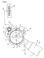
- the display device 16 stands Via a line 20 suitable for data transmission with a schematically shown data transmission connection device 21 in connection, which a housing 22 with a Sensor arrangement is assigned.
- the sensor arrangement 22 is a calibration device designated by 23 assigned which to the tread 6 of the tension pulley 5 is attachable.
- a transducer 24 is in the area the movement path of the stop 14 of the stop nose 13 of the second sub-element 3.
- the installation of the belt tensioner begins with the Belt tensioning device first with the internal combustion engine 10 loosely screwed and the first sub-element 1 by hanging the hooking lug 11 into a corresponding opening of the internal combustion engine against swiveling around the screw axis 2 is locked. Then the tension roller 5 is against the belt 7 pivoted, the pivoting movement by means of the attack of the tool 17 takes place. If the tension pulley 5 rests against the belt 7, one takes place Next pivoting movement. As a result of that under tension standing belts on the belt tensioner A second pivoting movement of the second sub-element takes place in the opposite direction 3 relative to the first sub-element 1. Reduced the angle ⁇ as shown in FIG. 1 until the with ⁇ '(Fig.
- the ad is within of the area "0", for example a corresponding one sounds acoustic signal or it becomes an optical signal (e.g. "green").
- the above the range "0" lying area marked with “+” corresponds to one Exceeding range and that below the range “0" lying area “-” corresponds to an undershoot area. That the transducer arrangement and the data transmission device having housing is on the Calibration device 23, which is outside the investment area of the belt 7 is placed on the tension pulley 5. After reaching of the display area becomes "0" by the operator the belt tensioner firmly with the internal combustion engine 10 screwed, while the reached Working position of the sub-elements 1 and 3 relative to each other is fixed.
Landscapes
- Engineering & Computer Science (AREA)
- General Engineering & Computer Science (AREA)
- Mechanical Engineering (AREA)
- Devices For Conveying Motion By Means Of Endless Flexible Members (AREA)
Description
- Fig. 1
- eine schematische Darstellung einer Riemenspannvorrichtung in Draufsicht, wobei die Position der Teilelemente der Riemenspannvorrichtung in ihrer Position vor der Anbringung an einem Verbrennungsmotor (Anlieferungsposition) dargestellt sind;
- Fig. 2
- eine Darstellung entsprechend Fig. 1, jedoch in an einen Verbrennungsmotor eingebautem Zustand;
- Fig. 3
- Teilelemente der Riemenspannvorrichtung in Explosionsdarstellung;
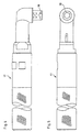
- Fig. 4 und Fig. 5
- jeweils um 90° zueinander versetzt Seitenansichten eines Verschwenkwerkzeuges;
- Fig. 6
- eine schematische Darstellung einer Riemenspannvorrichtung nach Arretierung des ersten Teilelementes relativ zu dem Verbrennungsmotor, jedoch vor dem Verschwenken, wobei außerdem schematisch ein Riemen, ein Verschwenkwerkzeug, eine Meßwertaufnehmeranordnung und eine extern angeordnete Anzeigeeinrichtung dargestellt sind;
- Fig. 7
- eine Teildarstellung entsprechend Fig. 6, in der das Gehäuse der Meßwertaufnehmeranordnung nur teilweise dargestellt und ein Meßwertaufnehmer gezeigt ist;
- Fig. 8
- eine Darstellung entsprechend Fig. 7, jedoch in verschwenkter Position, in der ein an einem ersten Teilelement der Riemenspannvorrichtung vorgesehener Anschlag gegen den Meßwertaufnehmer anliegt.
Claims (5)
- Verfahren zum Einbau einer eine Exzenteranordnung (4) aufweisenden Riemenspannvorrichtung an einen Verbrennungsmotor (10), bei dem die Riemenspannvorrichtung zunächst lose verschraubt und ein erstes Teilelement (1) der Riemenspannvorrichtung gegen ein Verschwenken um die Verschraubachse (2) gegenüber dem Verbrennungsmotor arretiert wird, anschließend eine über die Exzenteranordnung mit dem ersten Teilelement in Verbindung stehende Spannrolle (5) der Riemenspannvorrichtung gegen den Riemen (7) verschwenkt und nach Anlage gegen den Riemen in einer den Riemen spannenden Weise weiterverschwenkt wird, wodurch infolge der von dem unter Spannung stehenden Riemen auf die Riemenspannvorrichtung aufgebrachten Gegenkraft ein zwischen dem ersten Teilelement und der Spannrolle angeordnetes zweites Teilelement (3) der Riemenspannvorrichtung entgegen einer Vorspannkraft relativ zu dem ersten Teilelement in eine vorherbestimmte und die Arbeitsposition der Riemenspannvorrichtung bildende Winkellage verschwenkt und die Riemenspannvorrichtung dann fest mit dem Verbrennungsmotor verbunden wird wobei gleichzeitig die erreichte Arbeitsposition der Teilelemente relativ zueinander fixiert wird, dadurch gekennzeichnet, daß während der Verschwenkbewegung der Teilelemente (1, 3) relativ zueinander die Verschwenkwinkel gemessen und das Erreichen eines vorherbestimmten Verschwenkbereiches (α') angezeigt wird.
- Vorrichtung zur Durchführung des Verfahrens nach Anspruch 1, dadurch gekennzeichnet, daß eine mit der Riemenspannvorrichtung verbindbare Kalibriereinrichtung (23) mit einer die relative Winkellage der Teilelemente (1, 3) ermittelnden Meßwertaufnehmeranordnung (24) vorgesehen ist, und daß eine Anzeigeeinrichtung (16) zur Anzeige der jeweils ermittelten relativen Winkellage der Teilelemente (1, 3) vorgesehen ist.
- Vorrichtung nach Anspruch 2, dadurch gekennzeichnet, daß die Kalibriereinrichtung einen Teil eines Verschwenkwerkzeuges (17) zum Verschwenken der Teilelemente (1, 3) bildet.
- Vorrichtung nach Anspruch 2 oder 3, dadurch gekennzeichnet, daß wenigstens ein Teilelement (3) der Riemenspannvorrichtung einen Anschlag (14) für einen in der Bewegungsbahn des Anschlages liegenden Meßwertaufnehmer (24) der Kalibriereinrichtung (23) aufweist.
- Vorrichtung nach einem der Ansprüche 2 bis 4, dadurch gekennzeichnet, daß die Teilelemente (1, 3) der Riemenspannvorrichtung jeweils Anschläge (9, 14) aufweisen, und ein vorherbestimmter Winkelabstandsbereich (α') der Anschläge relativ zueinander einen Arbeitspositionsbereich für die Riemenspannvorrichtung darstellt, und daß die Kalibriereinrichtung (23) zur Messung der relativen Winkellage der Anschläge zueinander ausgebildet ist.
Applications Claiming Priority (2)
| Application Number | Priority Date | Filing Date | Title |
|---|---|---|---|
| DE19712907A DE19712907C1 (de) | 1997-03-27 | 1997-03-27 | Verfahren zum Einbau einer eine Exzenteranordnung aufweisenden Riemenspannvorrichtung an einen Verbrennungsmotor sowie Vorrichtung zur Durchführung dieses Verfahrens |
| DE19712907 | 1997-03-27 |
Publications (3)
| Publication Number | Publication Date |
|---|---|
| EP0867638A2 EP0867638A2 (de) | 1998-09-30 |
| EP0867638A3 EP0867638A3 (de) | 2000-07-12 |
| EP0867638B1 true EP0867638B1 (de) | 2002-09-11 |
Family
ID=7824806
Family Applications (1)
| Application Number | Title | Priority Date | Filing Date |
|---|---|---|---|
| EP98103228A Expired - Lifetime EP0867638B1 (de) | 1997-03-27 | 1998-02-25 | Verfahren zum Einbau einer eine Exzenteranordnung aufweisenden Riemenspannvorrichtung an einem Verbrennungsmotor sowie Vorrichtung zur Durchführung dieses Verfahren |
Country Status (2)
| Country | Link |
|---|---|
| EP (1) | EP0867638B1 (de) |
| DE (2) | DE19712907C1 (de) |
Families Citing this family (1)
| Publication number | Priority date | Publication date | Assignee | Title |
|---|---|---|---|---|
| DE102004009129A1 (de) * | 2004-02-25 | 2005-09-15 | Ina-Schaeffler Kg | Spannvorrichtung eines Endlostriebes, insbesondere eines Riementriebes |
Family Cites Families (4)
| Publication number | Priority date | Publication date | Assignee | Title |
|---|---|---|---|---|
| US4767383A (en) * | 1986-11-03 | 1988-08-30 | St John Richard C | Adjustable tensioner for belt and chain drives |
| DE3908817C1 (en) * | 1989-03-17 | 1990-05-10 | Skf Gmbh, 8720 Schweinfurt, De | Method for setting the tension of a drive belt |
| DE4015028A1 (de) * | 1990-05-10 | 1992-01-16 | Skf Gmbh | Voreinstellbare spannvorrichtung |
| DE4223324A1 (de) * | 1992-07-16 | 1994-01-20 | Schaeffler Waelzlager Kg | Mechanische Spannvorrichtung für einen Riemen- oder Kettentrieb |
-
1997
- 1997-03-27 DE DE19712907A patent/DE19712907C1/de not_active Expired - Fee Related
-
1998
- 1998-02-25 DE DE59805466T patent/DE59805466D1/de not_active Expired - Fee Related
- 1998-02-25 EP EP98103228A patent/EP0867638B1/de not_active Expired - Lifetime
Also Published As
| Publication number | Publication date |
|---|---|
| DE19712907C1 (de) | 1998-10-01 |
| DE59805466D1 (de) | 2002-10-17 |
| EP0867638A2 (de) | 1998-09-30 |
| EP0867638A3 (de) | 2000-07-12 |
Similar Documents
| Publication | Publication Date | Title |
|---|---|---|
| EP3008349B1 (de) | Adapter zur aufnahme eines medizintechnischen geräts sowie eines lageerfassungssystems | |
| DE19910828A1 (de) | Spanneinrichtung für Zugmittel | |
| WO2007014647A1 (de) | Andruckvorrichtung für ein spannsystem | |
| DE2824121A1 (de) | Dehnungsmessvorrichtung | |
| DE3873309T2 (de) | Bohrfeinmessvorrichtung. | |
| DE2941358A1 (de) | Befestigungsvorrichtung fuer ein kreissaegeblatt auf einem antriebszapfen | |
| DE19807822A1 (de) | Schwenklager | |
| DE10232088A1 (de) | Verdrehsicherung, insbesondere für ein Meßumformergehäuse | |
| EP1155782A2 (de) | Trägerkopf für eine Halterungsvorrichtung zur Halterung eines Werkstücks | |
| DE3908817C1 (en) | Method for setting the tension of a drive belt | |
| DE3212038A1 (de) | Verfahren und vorrichtung zum selbsttaetigen anziehen von mit gewinde versehenen befestigungsmitteln | |
| DE102016101264B3 (de) | Nockenwelleneinstellwerkzeug | |
| DE102017003759A1 (de) | Einstelleinrichtung und Verfahren zum Justieren eines Sensors zur Objektdetektion an einem Fahrzeug | |
| EP1832541B1 (de) | Prüfhebel mit Auflager | |
| DE19712907C1 (de) | Verfahren zum Einbau einer eine Exzenteranordnung aufweisenden Riemenspannvorrichtung an einen Verbrennungsmotor sowie Vorrichtung zur Durchführung dieses Verfahrens | |
| DE102020107629A1 (de) | Verfahren und Gerät zum Testen eines Antriebssystemspanners | |
| DE3510960C2 (de) | Radausrichtmeßgerät | |
| DE2600939A1 (de) | Anzugssystem mit einem qualitaetspruefgeraet | |
| AT394448B (de) | Vorrichtung zum messen von in eisenbahnschienen oder aehnlichen belasteten balken wirkenden kraeften | |
| DE102012222600A1 (de) | Vorrichtung und Verfahren zum Überprüfen eines Montageschlüssels | |
| DE102021133034A1 (de) | Kalibierverfahren für einen Riementrieb, Riementrieb und Blechbearbeitungsanlage | |
| DE112009001972T5 (de) | Verbesserungen bezüglich der Analyse von Konstruktionsgliedern | |
| DE19755253A1 (de) | Verfahren zum kontrollierten Anziehen einer Schraubverbindung | |
| DE102018130344B4 (de) | Band zur um eine Scharnierachse scharniergelenkigen Verbindung eines Flügels mit einem Rahmen | |
| DE202004001066U1 (de) | Drehwinkelmesseinrichtung |
Legal Events
| Date | Code | Title | Description |
|---|---|---|---|
| PUAI | Public reference made under article 153(3) epc to a published international application that has entered the european phase |
Free format text: ORIGINAL CODE: 0009012 |
|
| AK | Designated contracting states |
Kind code of ref document: A2 Designated state(s): DE FR GB |
|
| AX | Request for extension of the european patent |
Free format text: AL;LT;LV;MK;RO;SI |
|
| PUAL | Search report despatched |
Free format text: ORIGINAL CODE: 0009013 |
|
| AK | Designated contracting states |
Kind code of ref document: A3 Designated state(s): AT BE CH DE DK ES FI FR GB GR IE IT LI LU MC NL PT SE |
|
| AX | Request for extension of the european patent |
Free format text: AL;LT;LV;MK;RO;SI |
|
| 17P | Request for examination filed |
Effective date: 20000613 |
|
| AKX | Designation fees paid |
Free format text: DE FR GB |
|
| GRAG | Despatch of communication of intention to grant |
Free format text: ORIGINAL CODE: EPIDOS AGRA |
|
| GRAG | Despatch of communication of intention to grant |
Free format text: ORIGINAL CODE: EPIDOS AGRA |
|
| GRAH | Despatch of communication of intention to grant a patent |
Free format text: ORIGINAL CODE: EPIDOS IGRA |
|
| 17Q | First examination report despatched |
Effective date: 20020206 |
|
| GRAH | Despatch of communication of intention to grant a patent |
Free format text: ORIGINAL CODE: EPIDOS IGRA |
|
| GRAA | (expected) grant |
Free format text: ORIGINAL CODE: 0009210 |
|
| AK | Designated contracting states |
Kind code of ref document: B1 Designated state(s): DE FR GB |
|
| REG | Reference to a national code |
Ref country code: GB Ref legal event code: FG4D Free format text: NOT ENGLISH |
|
| GBT | Gb: translation of ep patent filed (gb section 77(6)(a)/1977) |
Effective date: 20020911 |
|
| REF | Corresponds to: |
Ref document number: 59805466 Country of ref document: DE Date of ref document: 20021017 |
|
| ET | Fr: translation filed | ||
| PLBE | No opposition filed within time limit |
Free format text: ORIGINAL CODE: 0009261 |
|
| STAA | Information on the status of an ep patent application or granted ep patent |
Free format text: STATUS: NO OPPOSITION FILED WITHIN TIME LIMIT |
|
| 26N | No opposition filed |
Effective date: 20030612 |
|
| REG | Reference to a national code |
Ref country code: FR Ref legal event code: TP |
|
| REG | Reference to a national code |
Ref country code: FR Ref legal event code: CD Ref country code: FR Ref legal event code: CA |
|
| PGFP | Annual fee paid to national office [announced via postgrant information from national office to epo] |
Ref country code: FR Payment date: 20060202 Year of fee payment: 9 |
|
| PGFP | Annual fee paid to national office [announced via postgrant information from national office to epo] |
Ref country code: DE Payment date: 20060228 Year of fee payment: 9 |
|
| GBPC | Gb: european patent ceased through non-payment of renewal fee |
Effective date: 20070225 |
|
| REG | Reference to a national code |
Ref country code: FR Ref legal event code: ST Effective date: 20071030 |
|
| PG25 | Lapsed in a contracting state [announced via postgrant information from national office to epo] |
Ref country code: DE Free format text: LAPSE BECAUSE OF NON-PAYMENT OF DUE FEES Effective date: 20070901 |
|
| PG25 | Lapsed in a contracting state [announced via postgrant information from national office to epo] |
Ref country code: GB Free format text: LAPSE BECAUSE OF NON-PAYMENT OF DUE FEES Effective date: 20070225 Ref country code: FR Free format text: LAPSE BECAUSE OF NON-PAYMENT OF DUE FEES Effective date: 20070228 |
|
| PGFP | Annual fee paid to national office [announced via postgrant information from national office to epo] |
Ref country code: GB Payment date: 20060109 Year of fee payment: 9 |