EP0867096B1 - Systeme radio cellulaire amad avec critere de qualite des canaux - Google Patents
Systeme radio cellulaire amad avec critere de qualite des canaux Download PDFInfo
- Publication number
- EP0867096B1 EP0867096B1 EP96944219A EP96944219A EP0867096B1 EP 0867096 B1 EP0867096 B1 EP 0867096B1 EP 96944219 A EP96944219 A EP 96944219A EP 96944219 A EP96944219 A EP 96944219A EP 0867096 B1 EP0867096 B1 EP 0867096B1
- Authority
- EP
- European Patent Office
- Prior art keywords
- channel
- sector
- assignment
- assigned
- cellular
- Prior art date
- Legal status (The legal status is an assumption and is not a legal conclusion. Google has not performed a legal analysis and makes no representation as to the accuracy of the status listed.)
- Expired - Lifetime
Links
Images


Classifications
-
- H—ELECTRICITY
- H04—ELECTRIC COMMUNICATION TECHNIQUE
- H04W—WIRELESS COMMUNICATION NETWORKS
- H04W72/00—Local resource management
- H04W72/50—Allocation or scheduling criteria for wireless resources
- H04W72/54—Allocation or scheduling criteria for wireless resources based on quality criteria
- H04W72/541—Allocation or scheduling criteria for wireless resources based on quality criteria using the level of interference
-
- H—ELECTRICITY
- H04—ELECTRIC COMMUNICATION TECHNIQUE
- H04W—WIRELESS COMMUNICATION NETWORKS
- H04W16/00—Network planning, e.g. coverage or traffic planning tools; Network deployment, e.g. resource partitioning or cells structures
- H04W16/02—Resource partitioning among network components, e.g. reuse partitioning
- H04W16/12—Fixed resource partitioning
-
- H—ELECTRICITY
- H04—ELECTRIC COMMUNICATION TECHNIQUE
- H04W—WIRELESS COMMUNICATION NETWORKS
- H04W16/00—Network planning, e.g. coverage or traffic planning tools; Network deployment, e.g. resource partitioning or cells structures
- H04W16/14—Spectrum sharing arrangements between different networks
-
- H—ELECTRICITY
- H04—ELECTRIC COMMUNICATION TECHNIQUE
- H04W—WIRELESS COMMUNICATION NETWORKS
- H04W16/00—Network planning, e.g. coverage or traffic planning tools; Network deployment, e.g. resource partitioning or cells structures
- H04W16/24—Cell structures
-
- H—ELECTRICITY
- H04—ELECTRIC COMMUNICATION TECHNIQUE
- H04W—WIRELESS COMMUNICATION NETWORKS
- H04W16/00—Network planning, e.g. coverage or traffic planning tools; Network deployment, e.g. resource partitioning or cells structures
- H04W16/24—Cell structures
- H04W16/28—Cell structures using beam steering
-
- H—ELECTRICITY
- H04—ELECTRIC COMMUNICATION TECHNIQUE
- H04W—WIRELESS COMMUNICATION NETWORKS
- H04W84/00—Network topologies
- H04W84/02—Hierarchically pre-organised networks, e.g. paging networks, cellular networks, WLAN [Wireless Local Area Network] or WLL [Wireless Local Loop]
- H04W84/10—Small scale networks; Flat hierarchical networks
- H04W84/14—WLL [Wireless Local Loop]; RLL [Radio Local Loop]
Definitions
- the invention is in the class of terrestrial cellular digital radio systems that provide demand assignment multiple access (DAMA) communications service to subscriber terminals equipped with narrowbeam radio antennas.
- DAMA demand assignment multiple access
- the subject class of cellular radio systems has a set of terrestrial radio base stations distributed over the service area, where each base station is equipped with sector antennas, and each sector antenna has associated transmitter/receivers that communicate via frequency division multiplexed (FDM) radio wave with subscriber terminals in the vicinity of the base station. Communications is two-way with radio wave transmission in the direction from base station to terminal termed the downlink direction, and in the direction from terminal to base station termed the uplink direction.
- Each subscriber terminal has a narrow beam antenna that is pointed into the aperture of one of the base station sector antennas assigned to the terminal.
- the terminal antenna has an associated transmitter and a receiver tunable to assigned sector FDM channels.
- the channel assignment originates in a service center on a DAMA basis.
- the FCC allocates a block of radio spectrum for specified terrestrial cellular radio services.
- the radio frequency band allocated to a cellular radio system is a precious natural resource, and it is of utmost concern to national and international regulatory agencies that the allocated radio spectra be efficiently used.
- increased spectral utilization efficiency implies reduction of the density of base stations required to cover a given service area.
- the resultant reduction of infrastructure cost may then result in reduction of service cost to subscribers.
- the realization of increased spectral utilization efficiency of cellular radio systems which is the objective of the invention has important economic and social benefits.
- Cellular radio systems employ frequency reuse of the block of spectra allocated to the cellular system in order to achieve high spectral efficiencies.
- the allocated block is partitioned into two parts, one part for radio wave transmission from base stations to the subscriber terminals, hereafter defined to be the uplink direction, and the other part for radio wave transmission from terminals to base stations, hereafter defined to be the uplink direction.
- the uplink part is further partitioned into frequency-division multiplexed (FDM) channels, and the channels are partitioned into N groups of channels F1, F2, ..., FN, where the number N is defined as the frequency reuse number.
- FDM frequency-division multiplexed
- a natural consequence of frequency reuse in cellular radio systems is that transmissions in the channel of one sector have the potential to interfere with transmissions in nearby co-channel sector and such interference is termed co-channel interference.
- Cellular systems utilize frequency allocation patterns that approximate idealized regular patterns known to have minimal co-channel interference levels for a given frequency reuse number N.
- the level of co-channel interference in a channel is defined in this disclosure as significant if it causes the channel to fail a defined channel quality criterion such as bit error rate.
- M fixed fixed base station complexity
- N the frequency reuse number
- LMDS local multipoint distribution systems
- Narrow beams have a known advantage in terms of mitigating multipath interference and reduction in the general level of co-channel interference.
- the objective of the present invention is to take advantage of the fact that the proportion of significant co-channel interferers in the system is typically very small so that special treatment in channel assignment for that population is possible.
- the objective of the present invention is to provide DAMA channel assignment under a guaranteed channel quality criterion and with much higher spectral efficiencies than prior art.
- a cellular RF communication system having a plurality of base stations, each base station communicating with a plurality of assigned stationary subscriber stations, respectively, each base station constituting a cell having a plurality of sector beam antennas per cell, each sector beam antenna illuminating a predetermined sector of said cell with RF communication signals, a plurality of said assigned RF subscriber stations being assigned to each sector of a cell, each subscriber station having an RF transceiver and a high gain antenna with a narrow beam width oriented toward the sector beam antenna oriented toward its assigned sector.
- the invention is a terrestrial cellular radio system comprised of a plurality of base stations distributed about a service area, and a plurality of subscriber terminals in the service area.
- Each base station has M sector antennas that service an area termed a cell that is centered at the base station.
- Each antenna defines a cell sector that has a channel FDM subgroup allocated for uplink communications and an FDM channel subgroup allocated for downlink communications in a cellular reuse pattern.
- Each terminal is assigned to one of the sectors according to a sector assignment algorithm, and the terminal's antenna is accordingly pointed at the sector antenna to which it is assigned. Terminals request and receive assignment of channel resources from the channel group allocated to the sector from a DAMA channel assignment algorithm.
- a unique feature of the invention is that its DAMA channel assignment procedure utilizes a database of prior information about the co-channel interference characteristics of terminals to assign channels in such a way that excessive co-channel interference gets harmlessly concentrated into a relatively small number of channels marked for interference and not assigned for communications.
- the channel assignment algorithm is capable of offering guaranteed channel quality while avoiding the large frequency reuse numbers required in prior art to achieve such guarantees.
- the invention maintains a high level of spectral utilization efficiency.
- the invention provides for automated means to generate the database of prior information about terminal characteristics, and the database is also used to ensure that adjacent channel interference is not excessive and received signal power is adequate to meet the guaranteed channel quality criterion.
- the invention is based on two key observations about uplink co-channel interference when subscriber terminal antennas have narrow beamwidths: (1) typically only a small proportion of terminals are significant co-channel interferers, and (2) when a terminal is a significant co-channel interferer its transmissions typically only interfere with at most one nearby co-channel sector.
- the DAMA uplink channel assignment procedure assigns channels to the relatively small number of subscribers known to be co-channel interferers in such a way that the co-channel interference always falls in one of a relatively small number of channels reserved only for such interference.
- the channels marked for interference are not assigned for communications in the sector in which the interference occurs so that significant co-channel interference is virtually eliminated from the channels assigned and used by terminals.
- the channels marked for interference represent wasted overhead, they are not only small in number relative to the totality of available channels, but also smaller in number than the population of terminals that are significant co-channel interferers. This is because under the DAMA assignment algorithm each unused channel marked for interference typically contains co-channel interference from more than one terminal.
- the invention works similarly for downlink assignments except that the location of interferer and interfered radio is reversed; i.e., certain downlink channels are marked as unassignable in certain sectors because they cause co-channel interference in terminal receivers in neighboring co-channel sectors.
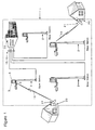
- the invention is a terrestrial cellular radio system [1] that comprises a plurality of base stations [2], plurality of subscriber terminals [20] with narrow-beam antennas [21], and a service center [30].
- the base stations [2] are distributed over a service area in a spatial pattern that roughly approximates an idealized cellular plan.
- the sector antennas of a base station provide service coverage of a region centered at the base station.
- Each terminal communicates by line-of-sight or near line-of-sight radio wave propagation path [19] from terminal antenna [21] to an assigned base station sector antenna [3].
- Trunk lines [15],[16] relay terminal communications data from base stations to the service center [30] where interconnection to telecommunications services occur.
- Fig. 2 shows by way of typical example the structure of each base station.
- Each base station sector antenna [3] is connected to a set of frequency division multiplexed (FDM) radio transmitters [5] that generate a set of FDM radio channels for downlink digital communications.
- the FDM channel radio frequencies are a set F that is allocated to a sector.
- each base station sector antenna [3] is connected to a set of FDM radio receivers [4] having a set of FDM uplink radio frequency channels for digital communications with allocated set G of radio frequencies.
- One of the radio channels of an uplink FDM set is reserved for uplink net management (NM) data and all other radio channels of the FDM set are assigned for uplink user data.
- NM net management
- each downlink FDM set is reserved for downlink NM data and all other radio channels of the FDM set are assigned for downlink user data
- Each receiver of an FDM receiver set [4] demodulates a digital data stream [6] of an uplink channel where the data is uplink NM data [6a] for the NM channel, and uplink user data [6b] for all other channels of the FDM set. Additionally, the receiver for the uplink NM channel measures power in the NM channel, with resultant power measurement data [8].
- Demodulated uplink data [6a] and [6b] are multiplexed [10] to form a downlink sector trunk [12] which is multiplexed [14] with all other downlink sector trunks of the base station to form the uplink base station trunk [16] which is routed to the service center.
- the downlink base station trunk [15] from the service center is demultiplexed [13] to yield downlink sector trunks [11] for each sector of the base station, and each downlink sector trunk [11] is further demultiplexed [9] to yield the downlink NM data [7a] for the downlink NM channel, and the user data [7b] for each of the downlink user data channels of the sector.
- the downlink data [7] for each channel is modulated onto the channel waveform by respective FDM channel transmitters [5].
- Fig. 3 shows by way of typical example the structure of the service center and the net management functions contained therein.
- each incoming uplink base station trunk [16] is demultiplexed [31] to obtain uplink data [6] for all uplink channels of all sectors of the base station, and power measurements [8] for each NM channel of each sector of the base station.
- the uplink NM data [6a] and power measurements [8] of each sector of each base station are routed by switch [33] to net management [40] in the service center, and the uplink user data [6b] is routed to service provider switches.
- Switch control is exercised by the NM controller that has knowledge of the required switch mapping of trunk channels to terminals and the telecommunications services to terminals.
- downlink user data [7b] from service providers, and downlink net management data [7a] are switched [34] and multiplexed [32] into the appropriate base station trunk [15].
- net management refers to control for efficient usage of cellular radio system resources, and the description of net management describes only novel net management functions or those functions that support novel or unique aspects of the invention.
- Net management is coordinated by the controller [41], and comprises two types of data processing elements: (1) data bases which include the cellular frequency plan [42], channel assignment list [43], terminal characteristics table [44], and terminal sector assignments [48]; and (2) algorithms for channel assignment [46], for power control, [45], and for sector assignment [47].
- the net management elements are typically embodied in microprocessor firmware and executed by microprocessor and supporting data processing peripherals, but implementation in discrete logic is also possible.
- Fig. 4 shows by way of typical example the structure of a terminal.
- Each terminal [20] has a radio transmitter [22] with means to tune to any uplink FDM channel frequency of a sector and means to vary output power level.
- Each receiver [23] has means to tune to any downlink FDM channel frequency of a sector. Both transmitter and receiver are connected to the terminal antenna [21].
- the terminal controller [24] controls uplink frequency, downlink frequency, and transmitter power level.
- the transmitter [22] modulates uplink digital data [6] onto the uplink channel, and if the channel is the NM channel, the digital data is uplink NM data [6a] that is routed by the switch [25] from the terminal controller [24].
- the uplink digital data [6] is user data [6b] that is routed from an external data input/output port [26].
- the receiver [23] demodulates downlink digital data [7] from the downlink channel, and if the channel is the NM channel the digital data is downlink NM data [7a] which is routed by switch [25] to the terminal controller; otherwise the data is downlink user data [7b] which is routed by switch [25] to the external user data input/output (I/O) port [26].
- Subscribers utilize the user data port [26] for interconnections of subscriber telecommunications user devices such as phones, modems, personal computers, and multimedia devices with the telecommunications services interconnected at the service center.
- the NM controller [41] controls terminals and their usage of system resources by two-way NM communications of NM messages [6a], [7a] with terminal controllers via base stations.
- Each terminal controller establishes a communications connection to the NM management controller when it tunes its transmitter [22] and receiver [23] to the net management channel of the sector assigned to the terminal.
- the sharing of a single net management channel by the multitude of terminals assigned to the sector may be managed by any suitable means known to those skilled in the art. For example, round-robin polling by the NM controller may be used for slow net management services such as terminal status monitoring, and random access used by terminals for rapid channel assignment requests.
- Uplink NM messages [6a] originating at a terminal that are relevant to the invention include (1) service request, (2) service logoff, and (3) terminal status; messages, and (4) net entry uplink.
- Downlink NM messages [7a] originating at the NM controller that are relevent to the invention include (1) service response, (2) power control.
- the cellular frequency plan [31] in the service center net management is a database table that defines the current allocation of FDM channel frequency groups to base station sectors.
- the uplink and downlink spectra allocated by the FCC to the cellular system are each partitioned into FDM channels.
- the channels are grouped into FDM channel groups F1, ..., FN, and similarly FDM channel groups G1, G2, ..., GN for the downlink.
- Each cell sector is allocated one of the downlink channel groups for the sector transmitter set [5] and one of the uplink channel groups for the sector receiver set [4], and the aggregate allocations over the service area define the frequency reuse pattern or frequency plan.
- a cellular frequency plan suitable for narrowbeam antennas is shown in the example in Fig. 5.
- N 2 frequency groups F1 and F2
- the assignment of frequency group Fi is denoted either Vi or Hi according to whether that frequency group is vertical or horizontal polarization.
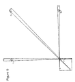
- Fig. 6 shows the conditions for a terminal in sector 7c to be an uplink co-channel interferer in one of three possible neighboring first-tier co-channel sectors.
- a terminal in sector 7c can be a co-channel interferer in a neighboring co-channel sector only if its narrow beam looks into the aperture of a co-channel sector with the same polarization, and this is possible only in sectors 1c, 3c or 9c in Fig. 5.
- co-channel interference is possible only if the assigned sector and the co-channel sector line up in the narrow terminal beam. It is also evident in the geometry of Fig.
- a terminal can be a significant co-channel interferer in at most one co-channel sector. This implies that there is only a narrow strip of terminal locations around the perimeter of sector 7c where a terminal can be a co-channel interferer. For randomly placed subscriber terminals in a sector, the proportion of terminals that are co-channel interferers will presently shown to be very small.
- the invention first determines which terminals are significant co-channel interferers by means of measurements in the following way.
- the invention utilizes power control of transmitter power levels to achieve a system-wide uniform received signal power level S at base station sector receivers.
- the power control has two objectives (1) minimize uplink adjacent channel interference in sector FDM receivers, and (2) provide known power reference levels to enable accurate measurement of co-channel interference characteristics of terminals. Both objectives are important supporting features of the invention in providing guaranteed channel quality as presently described.
- the terminal controller [24] causes each terminal transmitter [22] to transmit status messages [6a] at roughly periodic intervals, either in response to polling messages [7a] from the NM controller [41] in the service center, or in synchrony with preassigned status message time slots in the uplink net management channel.
- the power level of all status message are measured in the net management channel receiver of each base station sector. Based on power measurements received the power control algorithm [45] in the service center sends power directive NM messages to each terminal controller [24] to cause iterative adjustment of terminal transmitter power level until all signal power levels at all sector receivers converge to the same target power level S.
- the power control algorithm gathers measured power levels Ic [10] of each terminal's status message transmission in neighboring co-channel sectors, and the associated co-channel interference ratio S/Ic computed. If a terminal's status message transmissions cause measured co-channel S/Ic to fall below, or violates, a co-channel interference quality criterion Qc, the co-channel interference is termed significant, and the terminal termed an interferer; and the corresponding sector in which the significant co-channel interference occurred is hereafter termed the jammed sector. That is, there is associated with each interferer a jammed co-channel sector.
- the power measurement algorithm generates a table of terminal characteristics which tabulates by terminal ID following data: (1) the assigned sector ID, (2) whether a terminal is an interferer or a non-interferer, and if an interferer, (3) the ID of the associated jammed sector wherein the terminal induces the significant level of co-channel interference.
- the service request message implies a request for two resources jointly, (1) interconnection to a specified telecommunications service at the service center, and (2) channel assignment of base station FDM user channel resources as required to support the interconnection or data transport.
- the channel assignment is performed by the channel assignment algorithm [46] by searching for an available channel in the channel assignment table [43] in the following way.
- the channel assignment table [43] is a state machine representing current channel assignments and co-channel interference conditions in the system, and there are 2N subtables, one subtable for each uplink and downlink channel group and for each polarization used.
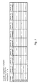
- Fig. 7 illustrates a subtable example for the Fig. 5 frequency plan, for frequency group F1, with vertical polarization.
- the co-channel sectors in the subtable are 7c, 1c, 9c, and 3c.
- the row indices correspond to all the channels in the channel group F1, and for simplicity only 8 channels are illustrated for the group as C1, C2, ..., C8.
- the column heading give sector ID's for the four co-channel sectors. Each channel can be assigned at most once in each sector, so each sector has a column for marking channels that are assigned to terminals.
- each channel in each sector can be jammed, i.e., suffer significant co-channel interference, so each sector has a second column to mark if a channel is jammed.
- the channel assignment algorithm marks a channel as assigned in a sector when the channel is assigned to a terminal in the sector. If the terminal is an interferer, the channel must be marked as jammed in the column corresponding to the jammed sector. In this way the channel assignment subtable indicates the state of current assignments in all co-channel sectors and which channels are jammed in all co-channel sectors.
- the channel assignment algorithm [46] utilizes the channel assignment table [43] to assign channels under a channel quality constraint. Referring to Fig. 7, the following assignment restrictions are evident. For a guaranteed channel quality criterion, the channel assignment algorithm may not assign a channel in a sector (1) to any terminal if that channel is marked as jammed in that sector, or (2) to an interferer terminal if that channel is currently assigned in the interferer's jammed sector.
- Restriction (1) is necessary to avoid assignment in a channel containing significant co-channel interference that violates the channel quality criterion
- restriction (2) is necessary to preclude the possibility that a new channel assignment may cause jamming of a currently assigned channel, thereby causing the currently assigned channel that previously met the quality criterion to now fail the quality criterion.
- Fig. 7 example there are 2N-1 other subtables in the channel assignment table for the other 2N-1 channel groups, but all 2N-1 subtables are independent state machines because co-channel interference is confined to co-channel sectors
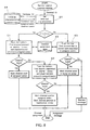
- the channel assignment algorithm first retrieves [50] the terminal characteristics, i.e., the terminal type (interferer or non-interferer), assigned sector ID, and if an interferer, the jammed sector ID. Then the channel assignment algorithm searches the terminal sector's channel assignment subtable, where the search procedure [51][52] starts at the bottom of the subtable if the terminal is an interferer, and starts at the top of the subtable if the terminal is a non-interferer [53].
- the channel assignment logic in either case obeys the restrictions described earlier associated with guaranteed channel quality criterion.
- the channel assignment algorithm optimally concentrates significant co-channel interference into the smallest number of jammed unassigned channels.
- the search for channel assignments [51] initially attempts a channel assignment that causes the resultant co-channel interference generated by the terminal to fall on an already jammed channel in the jammed sector.
- the efficiency of concentrating co-channel interference into a few unassigned channels is further enhanced by maximal separation of interferers and non-interferers at opposite ends (top and bottom) of the channel assignment subtable by the channel assignment algorithm. This is because when a jammed channel exists, concentration of additional co-channel interference in the jammed channel implies additional assignment of channels in the same row of the subtable. If a non-interferer is assigned in the same row of the subtable, one potential opportunity for co-channel interference concentration is removed.
- the channel quality criterion was based on a signal-to-co-channel interference metric.
- the invention applies to more general channel quality criteria.
- the channel quality criterion can be decomposed by techniques known to those skilled in the art into three joint criteria: (1) signal-to-co-channel interference ratio S/Ic > Qc , (2) signal-to-noise ratio S/N > Qn, and (3) signal-to-adjacent channel interference ratio S/Ia > Qa.
- the channel assignment algorithm [46] ensures that each assigned channel meets criterion (1) relative to co-channel interference impairment.
- the criterion (2) relative to thermal noise impairment can be implicitly met by setting the system wide target received power level S of the power control algorithm [45] high enough above the thermal noise level to meet the criterion.
- the criterion (3) relative to adjacent channel interference impairment can be met by well-known waveform design techniques and channel spacing procedures known to those skilled in the art. In this way the invention provides for a guaranteed BER quality criterion .
- the efficiency of the channel assignment algorithm is computed as follows for narrow-beam terminal antennas. For a given channel quality criterion, the proportion W of terminals that are interferers is first determined. Because the algorithm concentrates co-channel interference into the unassigned jammed channels, and each interferer terminal jams at most one co-channel sector, the overhead associated with unassigned, jammed channels is upper-bounded by W. Hence for efficiency E associated with a cellular frequency plan, the net spectral efficiency of the invention greater than E(1-W) . But for narrow-beam antennas, W is small (much less than one) so that E(1-W) ⁇ E.
- the idea of the invention is to start with a frequency plan with associated high spectral efficiency E that causes co-channel interference levels to be present in the system at a level that violate the channel quality criterion.
- the channel assignment algorithm will ensure through measurements that the channels with significant co-channel interference levels will not be assigned to terminals.
- the table of Fig. 9 shows a simplified comparison of efficiency and achievable channel quality criteria for both conventional DAMA channel assignment algorithm and the invention algorithm for the special case where propagation loss is proportional to range-squared.
- the second column of the table indicates the distance ratio r which is the minimum distance ratio of base station-to-co-channel interferer over base-station-to-assigned terminal.
- the conventional algorithm is assumed to be one that simply assigns any channel that is unassinged in the terminal's assigned sector.
- the conventional algorithm can guarantee any channel quality criterion Qc for signal-to-co-channel interference ratio only if Qc ⁇ _20log(r) at spectral efficiency E, and this is indicated in column 3.
- Qc > 20log(r) the conventional algorithm cannot meet the channel quality criterion at any spectral efficiency level.
- each terminal is labeled as either susceptible to co-channel interference or non-susceptible, and for each susceptible terminal there is the associated sector which is the source of the interference, and which is recorded in the terminal characteristics database.
- the downlink channel assignment table is analogous to the uplink channel assignment table of Fig. 7, with each column for marking of forbidden jammed channels on the uplink replaced with a column for marking of forbidden jamming channels on the downlink.
- the downlink channel assignment algorithm is analogous to the uplink channel assignment algorithm of Fig. 8 in an obvious way.
- the algorithm first looks at the assignments in the interfering sector and attempts to find a forbidden channel that is marked as an interferer, for assignment in the terminal's sector.
- the spectral efficiency of the algorithm for the downlink is computed analogously and hence is as efficient as the uplink if the same modulation, quality criterion, and frequency plan is used.
- the invention is extendable in ways obvious to those skilled in the art to the case where terminal narrowbeam antennas are steerable as in phased arrays and terminal motion occurs only between channel assignments.
- each of the FDM channels may be partitioned into smaller spectral units for assignment such as time-division slots, or code-division channels.
Landscapes
- Engineering & Computer Science (AREA)
- Quality & Reliability (AREA)
- Computer Networks & Wireless Communication (AREA)
- Signal Processing (AREA)
- Mobile Radio Communication Systems (AREA)
Claims (10)
- Système (1) de communication cellulaire RF ("Radio Frequency" - à fréquence radio) présentant une pluralité de postes de base (2), chaque poste de base communicant avec une pluralité de postes d'abonnés (20) stationnaires respectifs qui lui sont attribués, chaque poste de base (2) constituant une cellule, chaque cellule présentant une pluralité d'antennes (3) à faisceau sectoriel, chaque antenne (3) à faisceau sectoriel couvrant un secteur prédéterminé de ladite cellule par des signaux de communication RF, une pluralité desdits postes (20) d'abonnés RF attribués étant attribuée à chaque secteur d'une cellule, chaque poste d'abonné (20) présentant un émetteur-récepteur RF et une antenne (21) à haut gain à faisceau de largeur étroite orienté vers l'antenne (3) dont le faisceau sectoriel est orienté vers le secteur qui lui est attribué, caractérisé en ce que chaque poste de base (2) présente une base de données (44) de caractéristiques mesurées d'interférences sur canal commun qui reprend pour chaque poste d'abonné attribué (20) l'identité du secteur attribué, que le poste d'abonné (20) provoque des interférences ou n'en provoque pas, et s'il provoque des interférences, l'identité du secteur encombré associé dans lequel le poste d'abonné (20) induit un niveau significatif d'interférences sur canal commun,
et des moyens prévus dans un centre de service (20) relié aux postes de base (2), pour accéder à ladite base de données sur demande pour donner l'accès d'un canal de communication à l'un desdits postes d'abonné (20) attribués et pour, sur base dudit accès à la base de données, attribuer un canal de communication dans des conditions prédéterminées de qualité du canal en tentant initialement, au cas où le poste d'abonné (20) attribué crée des interférences, d'attribuer un canal qui amène les interférences sur canal commun créées par le poste d'abonné (20) attribué à tomber sur un canal déjà encombré dans le secteur encombré. - Système (1) de communication cellulaire RF selon la revendication 1, caractérisé en outre en ce que ledit centre de service (30) communique par des fils, des câbles ou d'autres canaux classiques avec chacun parmi ladite pluralité de postes de base (2) et en ce qu'il contient des éléments de contrôle adaptés pour sélectionner et attribuer un canal de fréquence à chaque activité de communication requise pour contrôler la qualité de la communication en limitant la quantité d'interférences sur canal commun et de bruit dans le canal attribué.
- Système (1) de communication cellulaire RF selon la revendication 1, caractérisé en outre en ce que chaque poste de base est équipé pour envoyer des signaux de contrôle dans les deux directions entre chaque antenne de poste de base et chacun de ses postes d'abonné (20), la puissance des signaux directs reçus, des signaux d'interférences sur canal commun et du bruit étant mesurée pendant ces transmissions et conservée dans le centre de service (30) qui communique avec tous les postes de base (2), les résultats desdites mesures étant utilisés à la demande d'un poste d'abonné (20) pour attribuer un canal de communication, pour déterminer si un canal disponible quelconque peut satisfaire les exigences d'interférences sur canal commun, entre canaux adjacents et en termes de bruit.
- Système (1) de communication cellulaire RF selon la revendication 3, dans lequel les signaux de contrôle spéciaux sont émis périodiquement sous le contrôle du centre de service (30).
- Système (1) de communication cellulaire RF selon la revendication 3, dans lequel la sélection de l'attribution d'un canal et du niveau de puissance émise dans un canal de communication requis est basée sur une spécification qui implique la combinaison d'une spécification de rapport signal-bruit, d'une spécification d'un rapport entre le signal et les interférences sur canal commun et de la spécification d'un rapport entre un signal et les interférences avec un canal de fréquences adjacent.
- Système (1) de communication cellulaire RF selon la revendication 3, dans lequel le contrôle de la qualité du signal est assuré en faisant passer des signaux de contrôle entre le poste de base et les postes d'abonnés (2, 20), en surveillant les niveaux d'interférence et de bruit dans le récepteur, en conservant numériquement les résultats dans le centre de service (30) et en utilisant une logique programmée pour sélectionner un canal optimal et un niveau de signal optimal pour chaque attribution.
- Système (1) de communication cellulaire RF selon la revendication 6, dans lequel la logique programmée sélectionne une attribution optimale de canal en cherchant un canal de fréquence qui n'est pas effectivement encombré par un canal de communication attribué précédemment et qui n'encombrera pas d'autres canaux précédemment attribués.
- Système (1) de communication cellulaire RF selon la revendication 6, dans lequel la logique programmée est conçue pour chercher un canal disponible qui n'est pas encombré, qui n'encombrera pas d'autres canaux précédemment attribués et qui réduira également la probabilité qu'une attribution ultérieure de canal soit gênée à cause de cette attribution.
- Système (1) de communication cellulaire RF selon la revendication 7, dans lequel la logique programmée évalue et crée une attribution optimale de canal par les étapes consistant à:pour chaque centre de service (30), créer initialement un tableau ordonné qui reprend pour chaque canal attribuable, tous les secteurs angulaires d'autres postes de base (2) qui seront encombrés sur canal commun par cette attribution;lors de chaque demande d'attribution de canal par un poste d'abonné (20), si le poste d'abonné (20) qui émet la demande est un poste d'abonné susceptible d'interférer avec d'autres secteurs, découvrir et sélectionner dans le tableau le dernier canal qui est encombré dans un secteur qui crée des interférences mais qui n'est pas encombré et actuellement non utilisé dans le présent secteur; s'il n'existe pas un tel canal, chercher le dernier canal non encombré dans un secteur qui crée des interférences; s'il n'y a pas un tel canal, bloquer l'attribution;Si le poste d'abonné (20) qui émet la demande n'est pas susceptible d'interférer avec d'autres, découvrir et sélectionner le premier canal du tableau qui est actuellement non attribué et non encombré dans le présent secteur, le sélectionner et l'attribuer; s'il n'en existe pas, bloquer l'attribution.
- Système (1) de communication cellulaire RF selon la revendication 7, dans lequel chaque canal de fréquences est en outre multiplexé par division dans le temps ou par division par code pour supporter des postes d'abonnés (20) supplémentaires, les attributions de canal étant réalisées pour plusieurs postes d'abonnés (20) de telle sorte qu'ils partagent le secteur et le canal de fréquences du poste de base (2).
Applications Claiming Priority (3)
| Application Number | Priority Date | Filing Date | Title |
|---|---|---|---|
| US08/570,439 US6301482B1 (en) | 1995-12-11 | 1995-12-11 | DMA cellular radio system with a channel quality criterion |
| US570439 | 1995-12-11 | ||
| PCT/US1996/019224 WO1997022218A1 (fr) | 1995-12-11 | 1996-12-11 | Systeme radio cellulaire amad avec critere de qualite des canaux |
Publications (3)
| Publication Number | Publication Date |
|---|---|
| EP0867096A1 EP0867096A1 (fr) | 1998-09-30 |
| EP0867096A4 EP0867096A4 (fr) | 2001-03-21 |
| EP0867096B1 true EP0867096B1 (fr) | 2003-03-19 |
Family
ID=24279651
Family Applications (1)
| Application Number | Title | Priority Date | Filing Date |
|---|---|---|---|
| EP96944219A Expired - Lifetime EP0867096B1 (fr) | 1995-12-11 | 1996-12-11 | Systeme radio cellulaire amad avec critere de qualite des canaux |
Country Status (7)
| Country | Link |
|---|---|
| US (2) | US6301482B1 (fr) |
| EP (1) | EP0867096B1 (fr) |
| AT (1) | ATE235135T1 (fr) |
| AU (1) | AU727412B2 (fr) |
| CA (1) | CA2238744A1 (fr) |
| DE (1) | DE69626844T2 (fr) |
| WO (1) | WO1997022218A1 (fr) |
Families Citing this family (21)
| Publication number | Priority date | Publication date | Assignee | Title |
|---|---|---|---|---|
| US5818830A (en) * | 1995-12-29 | 1998-10-06 | Lsi Logic Corporation | Method and apparatus for increasing the effective bandwidth of a digital wireless network |
| US6865392B2 (en) * | 1998-10-30 | 2005-03-08 | Adc Telecommunications, Inc. | Using alternate polarization in fixed wireless system deployment for improved capacity |
| US6560459B1 (en) * | 1998-12-18 | 2003-05-06 | Nortel Networks Limited | CDMA frequency planning for fixed wireless application |
| FI112427B (fi) * | 1999-11-05 | 2003-11-28 | Nokia Corp | Menetelmä langattoman päätelaitteen ominaisuuksien määrittämiseksi multimediasanoman välityspalvelussa, multimediasanoman välityspalvelu ja multimediapäätelaite |
| US6781960B1 (en) * | 2000-02-16 | 2004-08-24 | Telefonaktiebolaget Lm Ericsson (Publ) | Wireless multi-point communication system having automatically-updated sector-based routing capabilities |
| EP1148750A1 (fr) * | 2000-04-22 | 2001-10-24 | Deutsche Thomson-Brandt Gmbh | Méthode de présélection de canal dans un système de radiocommunication |
| US6643277B2 (en) * | 2000-06-29 | 2003-11-04 | Harris Broadband Wireless Access, Inc. | Frequency re-use for point to multipoint applications |
| FI112307B (fi) | 2000-08-02 | 2003-11-14 | Nokia Corp | Viestintäpalvelu |
| US7231214B2 (en) | 2000-12-08 | 2007-06-12 | Harris Corporation | System and method for frequency re-use in a sectorized cell pattern in a wireless communication system |
| IL156338A0 (en) * | 2000-12-08 | 2004-01-04 | Harris Broadband Wireless Acce | System and method for frequency re-use in a sectorized cell pattern in a wireless communication system |
| US7260388B1 (en) * | 2001-04-20 | 2007-08-21 | Sprint Communications Company L.P. | Communication device qualification for broadband wireless service |
| US6810236B2 (en) | 2001-05-14 | 2004-10-26 | Interdigital Technology Corporation | Dynamic channel quality measurement procedure for adaptive modulation and coding techniques |
| US7068977B1 (en) * | 2002-10-11 | 2006-06-27 | Navini Networks, Inc. | Method and system for interference assessment and reduction in a wireless communication system |
| US7346321B2 (en) * | 2003-02-24 | 2008-03-18 | Autocell Laboratories Inc. | Apparatus for associating access points with stations using bid techniques |
| US7633901B2 (en) * | 2005-06-23 | 2009-12-15 | Autocell Laboratories, Inc. | Co-channel congestion method and apparatus |
| US8411616B2 (en) | 2005-11-03 | 2013-04-02 | Piccata Fund Limited Liability Company | Pre-scan for wireless channel selection |
| FI20055687A0 (fi) * | 2005-12-21 | 2005-12-21 | Nokia Corp | Radiokanavajako ja siirtoyhteyden sovitus solukkojärjestelmässä |
| CA2866948C (fr) | 2006-02-28 | 2017-05-16 | Helvetia Ip Ag | Procedes et appareil pour le chevauchement de secteurs physiques d'une antenne mimo |
| GB2469465B (en) * | 2009-04-14 | 2011-09-28 | Toshiba Res Europ Ltd | Method and apparatus for reducing Co-channel interference |
| JP5251776B2 (ja) | 2009-07-27 | 2013-07-31 | ソニー株式会社 | 基地局、通信システム、移動端末および中継装置 |
| US9288007B2 (en) | 2013-11-15 | 2016-03-15 | At&T Intellectual Property I, L.P. | Endpoint device antenna beam forming based jamming detection and mitigation |
Family Cites Families (13)
| Publication number | Priority date | Publication date | Assignee | Title |
|---|---|---|---|---|
| US5448753A (en) | 1988-09-05 | 1995-09-05 | Ahl; Karl-Axel | Wide area radio communication network system and method |
| JPH02312492A (ja) * | 1989-05-29 | 1990-12-27 | Nec Corp | 移動通信システムにおけるチャネル割り当て方式および基地局配置情報の学習方式 |
| US5093927A (en) * | 1989-10-20 | 1992-03-03 | Motorola, Inc. | Two-way communication system |
| DE69024339T2 (de) * | 1989-12-28 | 1996-08-14 | Nec Corp | Antennensystem zur Reduzierung gegenseitiger Störungen bei Benutzung gleicher Kanäle |
| US5243598A (en) * | 1991-04-02 | 1993-09-07 | Pactel Corporation | Microcell system in digital cellular |
| US5309503A (en) * | 1991-12-06 | 1994-05-03 | Motorola, Inc. | Dynamic channel assignment in a communication system |
| US5280630A (en) * | 1992-01-21 | 1994-01-18 | Motorola, Inc. | Method and apparatus for dynamic channel allocation |
| AU670955B2 (en) * | 1992-08-04 | 1996-08-08 | Koninklijke Philips Electronics N.V. | Mobile radio system |
| US5437054A (en) * | 1993-02-05 | 1995-07-25 | The Research Foundation Of State University Of New York | Method and apparatus of assigning and sharing channels in a cellular communication system |
| SE516173C2 (sv) * | 1993-02-16 | 2001-11-26 | Ericsson Telefon Ab L M | Anordning för telekommunikation |
| US5365571A (en) | 1993-05-24 | 1994-11-15 | Hughes Aircraft Company | Cellular system having frequency plan and cell layout with reduced co-channel interference |
| JP2518156B2 (ja) * | 1993-07-19 | 1996-07-24 | 日本電気株式会社 | 無線通信システムのチャネル割当方式 |
| JP2586316B2 (ja) * | 1993-12-22 | 1997-02-26 | 日本電気株式会社 | セクタ構成移動通信システム |
-
1995
- 1995-12-11 US US08/570,439 patent/US6301482B1/en not_active Expired - Fee Related
-
1996
- 1996-12-11 AU AU14083/97A patent/AU727412B2/en not_active Ceased
- 1996-12-11 DE DE69626844T patent/DE69626844T2/de not_active Expired - Fee Related
- 1996-12-11 WO PCT/US1996/019224 patent/WO1997022218A1/fr active IP Right Grant
- 1996-12-11 AT AT96944219T patent/ATE235135T1/de not_active IP Right Cessation
- 1996-12-11 CA CA002238744A patent/CA2238744A1/fr not_active Abandoned
- 1996-12-11 EP EP96944219A patent/EP0867096B1/fr not_active Expired - Lifetime
-
2000
- 2000-11-15 US US09/711,965 patent/US6415131B1/en not_active Expired - Fee Related
Also Published As
| Publication number | Publication date |
|---|---|
| ATE235135T1 (de) | 2003-04-15 |
| DE69626844D1 (de) | 2003-04-24 |
| DE69626844T2 (de) | 2004-01-29 |
| US6415131B1 (en) | 2002-07-02 |
| AU727412B2 (en) | 2000-12-14 |
| EP0867096A4 (fr) | 2001-03-21 |
| US6301482B1 (en) | 2001-10-09 |
| WO1997022218A1 (fr) | 1997-06-19 |
| EP0867096A1 (fr) | 1998-09-30 |
| AU1408397A (en) | 1997-07-03 |
| CA2238744A1 (fr) | 1997-06-19 |
Similar Documents
| Publication | Publication Date | Title |
|---|---|---|
| EP0867096B1 (fr) | Systeme radio cellulaire amad avec critere de qualite des canaux | |
| US7477914B2 (en) | Real-time spectrum management to increase frequency reuse | |
| US5649292A (en) | Obtaining improved frequency reuse in wireless communication systems | |
| US5513379A (en) | Apparatus and method for dynamic resource allocation in wireless communication networks utilizing ordered borrowing | |
| KR100902864B1 (ko) | 멀티 반송파 시분할 듀플렉스 이동 통신 시스템에서의유연한 비 대칭 서비스 지원 방법 | |
| US7039441B1 (en) | High speed fixed wireless voice/data systems and methods | |
| EP1021926B1 (fr) | Affectation de ressources de transmission de donnees entre differents reseaux | |
| CN101406085B (zh) | 蜂窝通信网络中的测量辅助的动态频率重用 | |
| US6961325B1 (en) | TDM-based fixed wireless loop system | |
| US6418317B1 (en) | Method and system for managing frequencies allocated to a base station | |
| US6205337B1 (en) | Use of sectorized polarization diversity as a means of increasing capacity in cellular wireless systems | |
| EP0963129B1 (fr) | Plan cellullaire avec sélection simultanée du secteur et du tranche de temps | |
| US5734983A (en) | Frequency assignment in a cellular radio system | |
| EP0924897A2 (fr) | Dynamische Verteilung von Mitteln für Breitbanddienste in einem drahtlosen Kommunikationssystem | |
| US5901355A (en) | Method using different frequencies and antenna types for remotes located in an inner or outer region of a cell | |
| Amitay et al. | Resource auction multiple access (RAMA) in the cellular environment | |
| CA2255355C (fr) | Methode et appareil permettant d'eviter les brouillages dans un systeme de telecommunications sans fil | |
| CA2237483A1 (fr) | Methode d'amelioration de la capacite des systemes radio cellulaires (mobiles et fixes) | |
| WO2019229827A1 (fr) | Station relais, station de commande, système de transmission de données et procédé de transmission de données | |
| AU750523B2 (en) | Cellular radio communication system with a channel quality criterion | |
| US7428423B2 (en) | Communication system with controlled talk around mode | |
| Icolari et al. | Beam pattern allocation strategies for satellite cognitive radio systems | |
| GB2332817A (en) | Downlink frequency overlay for cellular radio system | |
| WO2000047010A1 (fr) | Dispositif de planification de frequences dans des systemes cellulaires | |
| JP2000013851A (ja) | 無線チャネル割り当て方法 |
Legal Events
| Date | Code | Title | Description |
|---|---|---|---|
| PUAI | Public reference made under article 153(3) epc to a published international application that has entered the european phase |
Free format text: ORIGINAL CODE: 0009012 |
|
| 17P | Request for examination filed |
Effective date: 19980527 |
|
| AK | Designated contracting states |
Kind code of ref document: A1 Designated state(s): AT BE CH DE DK ES FI FR GB GR IE IT LI NL PT SE |
|
| A4 | Supplementary search report drawn up and despatched |
Effective date: 20010206 |
|
| AK | Designated contracting states |
Kind code of ref document: A4 Designated state(s): AT BE CH DE DK ES FI FR GB GR IE IT LI NL PT SE |
|
| RIC1 | Information provided on ipc code assigned before grant |
Free format text: 7H 04Q 7/22 A, 7H 04Q 7/38 B |
|
| 17Q | First examination report despatched |
Effective date: 20010412 |
|
| GRAG | Despatch of communication of intention to grant |
Free format text: ORIGINAL CODE: EPIDOS AGRA |
|
| RTI1 | Title (correction) |
Free format text: DAMA CELLULAR RADIO SYSTEM WITH A CHANNEL QUALITY CRITERION |
|
| RTI1 | Title (correction) |
Free format text: DAMA CELLULAR RADIO SYSTEM WITH A CHANNEL QUALITY CRITERION |
|
| GRAG | Despatch of communication of intention to grant |
Free format text: ORIGINAL CODE: EPIDOS AGRA |
|
| GRAH | Despatch of communication of intention to grant a patent |
Free format text: ORIGINAL CODE: EPIDOS IGRA |
|
| GRAH | Despatch of communication of intention to grant a patent |
Free format text: ORIGINAL CODE: EPIDOS IGRA |
|
| GRAA | (expected) grant |
Free format text: ORIGINAL CODE: 0009210 |
|
| AK | Designated contracting states |
Designated state(s): AT BE CH DE DK ES FI FR GB GR IE IT LI NL PT SE |
|
| PG25 | Lapsed in a contracting state [announced via postgrant information from national office to epo] |
Ref country code: NL Free format text: LAPSE BECAUSE OF FAILURE TO SUBMIT A TRANSLATION OF THE DESCRIPTION OR TO PAY THE FEE WITHIN THE PRESCRIBED TIME-LIMIT Effective date: 20030319 Ref country code: LI Free format text: LAPSE BECAUSE OF FAILURE TO SUBMIT A TRANSLATION OF THE DESCRIPTION OR TO PAY THE FEE WITHIN THE PRESCRIBED TIME-LIMIT Effective date: 20030319 Ref country code: GR Free format text: LAPSE BECAUSE OF FAILURE TO SUBMIT A TRANSLATION OF THE DESCRIPTION OR TO PAY THE FEE WITHIN THE PRESCRIBED TIME-LIMIT Effective date: 20030319 Ref country code: FI Free format text: LAPSE BECAUSE OF FAILURE TO SUBMIT A TRANSLATION OF THE DESCRIPTION OR TO PAY THE FEE WITHIN THE PRESCRIBED TIME-LIMIT Effective date: 20030319 Ref country code: CH Free format text: LAPSE BECAUSE OF FAILURE TO SUBMIT A TRANSLATION OF THE DESCRIPTION OR TO PAY THE FEE WITHIN THE PRESCRIBED TIME-LIMIT Effective date: 20030319 Ref country code: BE Free format text: LAPSE BECAUSE OF FAILURE TO SUBMIT A TRANSLATION OF THE DESCRIPTION OR TO PAY THE FEE WITHIN THE PRESCRIBED TIME-LIMIT Effective date: 20030319 Ref country code: AT Free format text: LAPSE BECAUSE OF FAILURE TO SUBMIT A TRANSLATION OF THE DESCRIPTION OR TO PAY THE FEE WITHIN THE PRESCRIBED TIME-LIMIT Effective date: 20030319 |
|
| REG | Reference to a national code |
Ref country code: GB Ref legal event code: FG4D |
|
| REG | Reference to a national code |
Ref country code: CH Ref legal event code: EP |
|
| REG | Reference to a national code |
Ref country code: IE Ref legal event code: FG4D |
|
| REF | Corresponds to: |
Ref document number: 69626844 Country of ref document: DE Date of ref document: 20030424 Kind code of ref document: P |
|
| PG25 | Lapsed in a contracting state [announced via postgrant information from national office to epo] |
Ref country code: SE Free format text: LAPSE BECAUSE OF FAILURE TO SUBMIT A TRANSLATION OF THE DESCRIPTION OR TO PAY THE FEE WITHIN THE PRESCRIBED TIME-LIMIT Effective date: 20030619 Ref country code: DK Free format text: LAPSE BECAUSE OF FAILURE TO SUBMIT A TRANSLATION OF THE DESCRIPTION OR TO PAY THE FEE WITHIN THE PRESCRIBED TIME-LIMIT Effective date: 20030619 |
|
| PG25 | Lapsed in a contracting state [announced via postgrant information from national office to epo] |
Ref country code: PT Free format text: LAPSE BECAUSE OF FAILURE TO SUBMIT A TRANSLATION OF THE DESCRIPTION OR TO PAY THE FEE WITHIN THE PRESCRIBED TIME-LIMIT Effective date: 20030620 |
|
| NLV1 | Nl: lapsed or annulled due to failure to fulfill the requirements of art. 29p and 29m of the patents act | ||
| PG25 | Lapsed in a contracting state [announced via postgrant information from national office to epo] |
Ref country code: ES Free format text: LAPSE BECAUSE OF FAILURE TO SUBMIT A TRANSLATION OF THE DESCRIPTION OR TO PAY THE FEE WITHIN THE PRESCRIBED TIME-LIMIT Effective date: 20030930 |
|
| REG | Reference to a national code |
Ref country code: CH Ref legal event code: PL |
|
| PG25 | Lapsed in a contracting state [announced via postgrant information from national office to epo] |
Ref country code: IE Free format text: LAPSE BECAUSE OF NON-PAYMENT OF DUE FEES Effective date: 20031211 |
|
| ET | Fr: translation filed | ||
| PLBE | No opposition filed within time limit |
Free format text: ORIGINAL CODE: 0009261 |
|
| STAA | Information on the status of an ep patent application or granted ep patent |
Free format text: STATUS: NO OPPOSITION FILED WITHIN TIME LIMIT |
|
| 26N | No opposition filed |
Effective date: 20031222 |
|
| REG | Reference to a national code |
Ref country code: IE Ref legal event code: MM4A |
|
| PGFP | Annual fee paid to national office [announced via postgrant information from national office to epo] |
Ref country code: DE Payment date: 20061218 Year of fee payment: 11 |
|
| PGFP | Annual fee paid to national office [announced via postgrant information from national office to epo] |
Ref country code: GB Payment date: 20061221 Year of fee payment: 11 |
|
| PGFP | Annual fee paid to national office [announced via postgrant information from national office to epo] |
Ref country code: IT Payment date: 20061231 Year of fee payment: 11 |
|
| PGFP | Annual fee paid to national office [announced via postgrant information from national office to epo] |
Ref country code: FR Payment date: 20061212 Year of fee payment: 11 |
|
| GBPC | Gb: european patent ceased through non-payment of renewal fee |
Effective date: 20071211 |
|
| PG25 | Lapsed in a contracting state [announced via postgrant information from national office to epo] |
Ref country code: DE Free format text: LAPSE BECAUSE OF NON-PAYMENT OF DUE FEES Effective date: 20080701 |
|
| REG | Reference to a national code |
Ref country code: FR Ref legal event code: ST Effective date: 20081020 |
|
| PG25 | Lapsed in a contracting state [announced via postgrant information from national office to epo] |
Ref country code: GB Free format text: LAPSE BECAUSE OF NON-PAYMENT OF DUE FEES Effective date: 20071211 |
|
| PG25 | Lapsed in a contracting state [announced via postgrant information from national office to epo] |
Ref country code: FR Free format text: LAPSE BECAUSE OF NON-PAYMENT OF DUE FEES Effective date: 20071231 |
|
| PG25 | Lapsed in a contracting state [announced via postgrant information from national office to epo] |
Ref country code: IT Free format text: LAPSE BECAUSE OF NON-PAYMENT OF DUE FEES Effective date: 20071211 |