EP0866923B1 - Friction engaging device - Google Patents
Friction engaging device Download PDFInfo
- Publication number
- EP0866923B1 EP0866923B1 EP96941775A EP96941775A EP0866923B1 EP 0866923 B1 EP0866923 B1 EP 0866923B1 EP 96941775 A EP96941775 A EP 96941775A EP 96941775 A EP96941775 A EP 96941775A EP 0866923 B1 EP0866923 B1 EP 0866923B1
- Authority
- EP
- European Patent Office
- Prior art keywords
- carbon
- silicon
- trackway
- guided
- friction engaging
- Prior art date
- Legal status (The legal status is an assumption and is not a legal conclusion. Google has not performed a legal analysis and makes no representation as to the accuracy of the status listed.)
- Revoked
Links
Images


Classifications
-
- C—CHEMISTRY; METALLURGY
- C04—CEMENTS; CONCRETE; ARTIFICIAL STONE; CERAMICS; REFRACTORIES
- C04B—LIME, MAGNESIA; SLAG; CEMENTS; COMPOSITIONS THEREOF, e.g. MORTARS, CONCRETE OR LIKE BUILDING MATERIALS; ARTIFICIAL STONE; CERAMICS; REFRACTORIES; TREATMENT OF NATURAL STONE
- C04B35/00—Shaped ceramic products characterised by their composition; Ceramics compositions; Processing powders of inorganic compounds preparatory to the manufacturing of ceramic products
- C04B35/515—Shaped ceramic products characterised by their composition; Ceramics compositions; Processing powders of inorganic compounds preparatory to the manufacturing of ceramic products based on non-oxide ceramics
- C04B35/56—Shaped ceramic products characterised by their composition; Ceramics compositions; Processing powders of inorganic compounds preparatory to the manufacturing of ceramic products based on non-oxide ceramics based on carbides or oxycarbides
- C04B35/565—Shaped ceramic products characterised by their composition; Ceramics compositions; Processing powders of inorganic compounds preparatory to the manufacturing of ceramic products based on non-oxide ceramics based on carbides or oxycarbides based on silicon carbide
- C04B35/573—Shaped ceramic products characterised by their composition; Ceramics compositions; Processing powders of inorganic compounds preparatory to the manufacturing of ceramic products based on non-oxide ceramics based on carbides or oxycarbides based on silicon carbide obtained by reaction sintering or recrystallisation
-
- F—MECHANICAL ENGINEERING; LIGHTING; HEATING; WEAPONS; BLASTING
- F16—ENGINEERING ELEMENTS AND UNITS; GENERAL MEASURES FOR PRODUCING AND MAINTAINING EFFECTIVE FUNCTIONING OF MACHINES OR INSTALLATIONS; THERMAL INSULATION IN GENERAL
- F16D—COUPLINGS FOR TRANSMITTING ROTATION; CLUTCHES; BRAKES
- F16D69/00—Friction linings; Attachment thereof; Selection of coacting friction substances or surfaces
- F16D69/02—Composition of linings ; Methods of manufacturing
-
- C—CHEMISTRY; METALLURGY
- C04—CEMENTS; CONCRETE; ARTIFICIAL STONE; CERAMICS; REFRACTORIES
- C04B—LIME, MAGNESIA; SLAG; CEMENTS; COMPOSITIONS THEREOF, e.g. MORTARS, CONCRETE OR LIKE BUILDING MATERIALS; ARTIFICIAL STONE; CERAMICS; REFRACTORIES; TREATMENT OF NATURAL STONE
- C04B35/00—Shaped ceramic products characterised by their composition; Ceramics compositions; Processing powders of inorganic compounds preparatory to the manufacturing of ceramic products
- C04B35/71—Ceramic products containing macroscopic reinforcing agents
- C04B35/78—Ceramic products containing macroscopic reinforcing agents containing non-metallic materials
- C04B35/80—Fibres, filaments, whiskers, platelets, or the like
-
- F—MECHANICAL ENGINEERING; LIGHTING; HEATING; WEAPONS; BLASTING
- F16—ENGINEERING ELEMENTS AND UNITS; GENERAL MEASURES FOR PRODUCING AND MAINTAINING EFFECTIVE FUNCTIONING OF MACHINES OR INSTALLATIONS; THERMAL INSULATION IN GENERAL
- F16D—COUPLINGS FOR TRANSMITTING ROTATION; CLUTCHES; BRAKES
- F16D69/00—Friction linings; Attachment thereof; Selection of coacting friction substances or surfaces
- F16D69/02—Composition of linings ; Methods of manufacturing
- F16D69/023—Composite materials containing carbon and carbon fibres or fibres made of carbonizable material
-
- Y—GENERAL TAGGING OF NEW TECHNOLOGICAL DEVELOPMENTS; GENERAL TAGGING OF CROSS-SECTIONAL TECHNOLOGIES SPANNING OVER SEVERAL SECTIONS OF THE IPC; TECHNICAL SUBJECTS COVERED BY FORMER USPC CROSS-REFERENCE ART COLLECTIONS [XRACs] AND DIGESTS
- Y10—TECHNICAL SUBJECTS COVERED BY FORMER USPC
- Y10T—TECHNICAL SUBJECTS COVERED BY FORMER US CLASSIFICATION
- Y10T428/00—Stock material or miscellaneous articles
- Y10T428/21—Circular sheet or circular blank
- Y10T428/213—Frictional
-
- Y—GENERAL TAGGING OF NEW TECHNOLOGICAL DEVELOPMENTS; GENERAL TAGGING OF CROSS-SECTIONAL TECHNOLOGIES SPANNING OVER SEVERAL SECTIONS OF THE IPC; TECHNICAL SUBJECTS COVERED BY FORMER USPC CROSS-REFERENCE ART COLLECTIONS [XRACs] AND DIGESTS
- Y10—TECHNICAL SUBJECTS COVERED BY FORMER USPC
- Y10T—TECHNICAL SUBJECTS COVERED BY FORMER US CLASSIFICATION
- Y10T428/00—Stock material or miscellaneous articles
- Y10T428/30—Self-sustaining carbon mass or layer with impregnant or other layer
Definitions
- the present invention relates to a friction engaging device, such as, for example, a braking disc for a friction brake or friction clutch.
- the present invention relates to a high performance friction engaging device, such as, for example, a braking disc for use in a guided trackway vehicle.
- trains or their rolling stock conventionally have disc brakes which utilise steel or cast iron braking discs.
- the current maximum performance for a conventional train brake is that proposed for a new high speed passenger train where the maximum energy per steel braking disc in one stop is 22MJ, with an average deceleration calculated from 350 km/h to stationary of about 0.7ms -2 .
- a low margin between recovered fares and operating costs means the market price of a braking disc is relatively low and the life time requirement for the braking disc is high.
- each axle may have 400kg of braking discs.
- a greater number of braking discs adds to the weight of an axle and the greater the weight of the axle the greater the resulting track damage.
- a maximum of four steel braking discs due to their bulk, can be mounted on an axle, it is not very easy to increase the vehicle speeds much beyond 350 km/h using steel braking discs.
- the braking discs for an aircraft's brakes are in part determined by the type of flights they undergo.
- a jumbo jet may have as many as 9 x 16 clutch braking discs which are made of carbon-carbon fibre ie. a carbon fibre reinforced carbon composite.
- the current maximum performance for such a carbon-carbon fibre clutch brake is 71MJ with an average deceleration from about 290 - 320 km/h to zero of about 4.2ms -2 , this being the performance required to cater with an aborted take-off.
- the whole of the undercarriage of the aircraft, including the braking discs has to be replaced after such an aborted take-off. Consequently, with an aircraft it is less important that the braking discs wear characteristics are poorer than those provided by steel braking discs.
- steel braking discs may be preferred as steel, unlike carbon-carbon fibre, does not give rise to judder and gives better wear characteristics thus making steel braking discs more economical despite the need for increased fuel load, due to heavier brakes.
- US 5007508 discloses a frictional coupling carbon-carbon composite having carbon or silicon carbide reinforcement for use in aircraft brakes.
- EP 300756 discloses a brake element having a moulded carbon structure and friction surfaces thereas connected to refractory metal carbide.
- a guided trackway vehicle friction engaging device in the form of a carbon-ceramic composite consisting of a carbon fibre network and a filler, wherein the filler consists of silicon carbide, silicon oxide, silicon and free carbon.
- Such a composition can be made utilizing a number of known processes.
- the carbon-ceramic composite comprises, by volume 10 to 60% of a carbon fibre network and up to 90% by volume of a filler comprising silicon carbide.
- the filler may comprise a volume of air (porosity).
- the filler consists essentially of silicon carbide.
- the filler consists of silicon carbide, silicon oxide, silicon and free carbon.
- the carbon-ceramic composite may comprise, by volume, 10 to 60% of a carbon fibre network and 40 to 90% of a filler more preferably 30% of a carbon fibre network and 70% of a filler.
- the overall composition comprises:- Component Range Carbon fibre 3-53 Free carbon 4-76 Silicon carbide 7-37 silicon 3-19 silicon oxide 3-19
- the preferred ranges and actual weights will depend upon the carbon fibre content and the degree of impregnation.
- the porosity has no effect on the weight.
- the carbon-ceramic composite will comprise (end weight percent) : Component Range % Preferred Range % Preferred % Carbon Fibre 11 - 28 16 - 25 22,0 Free Carbon 15 - 59 30 - 55 46,8 Silicon Carbide 7 - 37 10 - 28 15,6 Silicon 3 - 19 5 - 14 7,8 Silicon oxide 3 - 19 5 - 14 7,8
- the carbon-ceramic composite For a material produced from a starting material, with a carbon fibre content of 10% by weight of the carbon-carbon composite after impregnation the carbon-ceramic composite will comprise (end weight percent); Component Range % Preferred Range % Carbon Fibre 3 - 9 5 - 9 Free Carbon 23 - 76 41 - 71 Silicon Carbide 7 - 37 10 - 28 Silicon 3 - 19 5 - 14 Silicon oxide 3 - 19 5 - 14 and, for a material produced from a starting material with a carbon fibre content of 60% by weight of carbon-carbon composite after impregnation the carbon-ceramic composite will comprise (end weight percent). Component Range % Preferred Range % Carbon Fibre 22 - 53 32 - 50 Free Carbon 4 - 33 14 - 30 Silicon Carbide 7 - 37 10 - 28 Silicon 3 - 19 5 - 14 Silicon oxide 3 - 19 5 - 14
- the carbon fibre network provides the friction engaging device with its good tensile properties and strength at high performance levels whilst the silicon carbide in the filler, provides the composite with its good wear, oxidation resistance and thermal properties.
- a method of producing a friction engaging device in the form of a carbon-carbon composite comprising substantially filling by impregnation, a free carbon containing volume, defined as the volume between respective fibres of a carbon fibre network, with silicon under conditions whereby all or substantially all of the carbon fibre network remains as carbon fibre, and a proportion of the free carbon present in the volume is converted within the volume to silicon carbide by reaction with the silicon.
- impregnation is meant the ability to add material by liquid and/or gaseous infiltration and/or by chemical reaction eg. diffusion without a significant increase in physical size.
- a method of producing a friction engaging device of the invention in which a carbon - carbon composite consisting 10 to 60% by weight of a carbon fibre network and from 40 to 90% by weight free carbon is impregnated with silicon under conditions such that substantially all of the carbon fibre network remains as carbon fibre, and a proportion of the free carbon present in the volume is converted within the volume to silicon carbide by reaction with the silicon.
- the free carbon is converted to silicon carbide, more preferably still about 20% for a composite made by impregnating a 30% by volume carbon-carbon composite.
- the friction engaging device is produced from a carbon-carbon composite with a density of 1.4 to 1.8g/cm 3 .
- the carbon-carbon composite has an open porosity of 10-30%, more preferably still 15%.
- the carbon-carbon composite has a thermal conductivity in an axial and radial direction of at least 12 W/mK.
- the carbon - carbon composite may comprise from 10 to 60% by weight of a carbon fibre network and from 40 to 90% by weight free carbon, any air (porosity) present in the structure having no effect on the weight.
- the carbon - carbon composite.which is subjected to impregnation with silicon comprises from 10 to 60% by weight of a carbon fibre network and from 90 to 40% by weight of free carbon.
- the volume which previously comprised free carbon and air is impregnated with silicon and the air content (porosity) thereby reduced, typically to about 5%.
- silicon may be introduced into the volume by impregnating the open space (porosity) with silicon by the REFEL process the silicon is reacted with a proportion of the free carbon to produce silicon carbide.
- the REFEL processing conditions are substantially as described in U.K. Patent Nos:1,437178 and 1,596303. However, it has been found that a silicon carbide seed is not essential to initiate the process to form the device of the present invention.
- a friction engaging device is produced as follows:
- a carbon-carbon composite such as that used in the manufacture of braking discs used in the aircraft and Formula One Racing Car industries, with a density between 1:4 and 1:8g/cm 3 , an open porosity between 10% and 30% and a thermal conductivity of at least 12 W/mK in the axial and in any radial directions, was machined to a desired shape by, for example, milling, grinding and turning.
- the carbon-carbon composite was thoroughly dried and silicon introduced substantially as per the REFEL process, the shaped carbon-carbon composite friction engaging device or a part therefore being placed in a refractory crucible with elemental silicon and subjected to heat (over 1600°C) in an inert atmosphere (i.e. Argon) or under vacuum.
- the liquid, and vapour silicon penetrates the volume via the open pore structure between the carbon fibre network, and a proportion of the free carbon, but unexpectedly not the carbon fibres, is converted into silicon carbide.
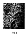
- Figs 1 to 3 are photomicrographs of the composite.
- Fig. 1 shows bundles (tows) of carbon fibres A with filler B coating the fibres.
- Fig. 2 shows distinct carbon fibres C with filler B coating the fibres and being dispersed throughout the structure
- Fig. 3 shows the filler B forming a solid mass D about the fibres C.
- the silicon carbide formed comprises a crystalline beta and alpha, though beta predominates, silicon carbide.
- the carbon-ceramic composite also comprises some unreacted silicon, a silicon oxide and unreacted carbon.
- silicon is introduced until there is no further weight gain in the product thereby indicating that the volume has been impregnated to its maximum.
- the resulting friction engaging device was then finished, by for example, grinding, and secured in a supporting structure eg. hub and web. If necessary, like parts are attached together on a supporting structure eg. hub and web, to form the desired braking disc.
- the assembly was mounted on a dynamometer shaft in a dynamometer and fitted with a caliper which held 400 cm 2 , 48mm thick, slotted pads composed according to the technology described in PCT WO 95/07418. On brake application the pads are forced onto the surface of the composite pieces.
- the dynamometer was set to run at full speed (1961 rpm) with an inertia of 10120 kgm 2 for braking from full speed to 1240 rpm and 9200 kgm 2 for braking from 1240 rpm to rest (this is a two stage brake application and is used on vehicles to control the deceleration from very high speeds). From full speed the brake was applied with 16.4 kN clamp force for the first stage and 15.2 kN for the second stage until the disc ceased to rotate. Throughout the brake application, the dynamometer monitored the speed, time, distance and inertia from which can be calculated the instantaneous friction coefficient, stop distance, braked mass, etc. Temperatures were also measured on the surface of the disc and on the steel structure beneath the composite pieces.
- the energy dissipated during the brake application was 44 MJ.
- the maximum temperature reached by the composite was 850°C and the carrier steel 350°C.
- Table 1 contrasts the energy per unit mass or volume of a braking disc and the power surface loading. It will be apparent that the braking disc of the present invention has more than double the energy handling capability of a steel braking disc.
- the braking disc of the present invention when used with a ceramic pad, showed a stable coefficient of friction in dry conditions at temperatures up to 1500°C. At very high duties, which is where this technology can out perform any other known technology, a high temperature. pad is required such as that disclosed in PCT WO 95/07418 which discloses a pad of friction material comprising at least 50% by weight of a ceramic material present in the form of relatively coarse particles of diameter 0.3mm to 4mm and a synthetic resin binder, together with a minor amount of a graphite lubricant and a minor amount of ceramic material in the from of relatively fine particles in the size range 1 to 30 microns.
- Wear behaviour was also found to be adequate for this type of application due, it is believed, to a stable friction under "snub stop" conditions avoiding the high wear mechanisms seen with carbon fibre braking discs, and due to the greater abrasion resistance of ceramic and ceramic composites compared to carbons.
- the oxidation resistance of silicon carbide is considered to be excellent and allows continuous use above 1200°C with excursions up to 1700°C being possible. Therefore the wear is low compared to known carbon-carbon constructions for all conditions.
- the wear behaviour of a brake disc according to the present invention is inferior (approx 2 x the wear rate, at twice the duty) but will be acceptable to the train industry if 50% more wear allowance is provided in the manufacture of the component.
- the device of the present invention thus offers the possibility of using carbon fibre reinforced ceramics across a wide spectrum of applications.
- it provides an opportunity for reducing the number, weight and bulk of braking discs for guided trackway vehicles, more particularly trains and their rolling stock, and provides an alternative which overcomes the problem of judder in aircraft braking discs, particularly at low taxiing speeds and may be useful for brake systems on other forms of transport, for example., cars, lorries etc..
- the discs were then all subjected to the same test procedure which consisted of spinning the disc to 5 000 rpm and applying a pad (with an area of 12.54cm 2 and of a composition according to PCT WO 95/07418) under load for one minute, followed by cooling for six minutes or until the temperature fell below 150°C.
- the disc was driven under load and the speed was maintained at 5 000 rpm, giving the effect of a drag brake.
- the pad loads were; two drags at each of 150N, and 315N and thirty four drags at 485N, 675N and 810N.
- the total energy absorbed was 12 MJ.
- torque and temperature was monitored, the latter being derived from a rubbing thermocouple placed on the disc brake surface at the effective brake radius.
- Both discs and pads (same pad type used for each test) were weighed prior to and after testing.
- the set and measured parameters were used to calculate energy absorbed, friction coefficient and wear rates for the pads and discs.
- the characteristics of the materials are shown in Table 2 below: The results shows that, although the friction coefficient range is larger for the ALC materials, the disc and pads wear a lot less than the SA3 material under the same test conditions.
Landscapes
- Engineering & Computer Science (AREA)
- Chemical & Material Sciences (AREA)
- Ceramic Engineering (AREA)
- General Engineering & Computer Science (AREA)
- Materials Engineering (AREA)
- Chemical Kinetics & Catalysis (AREA)
- Manufacturing & Machinery (AREA)
- Structural Engineering (AREA)
- Organic Chemistry (AREA)
- Mechanical Engineering (AREA)
- Composite Materials (AREA)
- Braking Arrangements (AREA)
Description
Consequently, with an aircraft it is less important that the braking discs wear characteristics are poorer than those provided by steel braking discs.
| Component | Range |
| Carbon fibre | 3-53 |
| Free carbon | 4-76 |
| Silicon carbide | 7-37 |
| silicon | 3-19 |
| silicon oxide | 3-19 |
| Component | Range % | Preferred Range % | Preferred % |
| Carbon Fibre | 11 - 28 | 16 - 25 | 22,0 |
| Free Carbon | 15 - 59 | 30 - 55 | 46,8 |
| Silicon Carbide | 7 - 37 | 10 - 28 | 15,6 |
| Silicon | 3 - 19 | 5 - 14 | 7,8 |
| Silicon oxide | 3 - 19 | 5 - 14 | 7,8 |
| Component | Range % | Preferred Range % |
| Carbon Fibre | 3 - 9 | 5 - 9 |
| Free Carbon | 23 - 76 | 41 - 71 |
| Silicon Carbide | 7 - 37 | 10 - 28 |
| Silicon | 3 - 19 | 5 - 14 |
| Silicon oxide | 3 - 19 | 5 - 14 |
| Component | Range % | Preferred Range % |
| Carbon Fibre | 22 - 53 | 32 - 50 |
| Free Carbon | 4 - 33 | 14 - 30 |
| Silicon Carbide | 7 - 37 | 10 - 28 |
| Silicon | 3 - 19 | 5 - 14 |
| Silicon oxide | 3 - 19 | 5 - 14 |
However not all the silicon introduced is converted into silicon carbide, some remains as silicon and some is converted to a silicon oxide.
| Braking Disc Type | Test Type | Energy Per Unit Mass(MJ/Kg) | Energy Per Unit Volume (MJ/m2 | Peak Power Per Swept Area (MW/m2. | Emergency Average Deceleration (ms-2) |
| Steel | For Train App. | 0.28 | 1.8 | 0.6 | 1.1 |
| Carbon Fibre reinforced ceramic | For Train App. | 0.37 | 1.8 | 1.2 | 1.1 |
| Carbon-carbon | For Aircraft | 2.21 | 4.0 | 4.5 | 4.4 |
The characteristics of the materials are shown in Table 2 below:

Claims (19)
- A guided trackway vehicle friction engaging device in the form of a carbon - ceramic composite consisting of a carbon fibre network and a filler, wherein the filler consists of silicon carbide, silicon oxide, silicon and free carbon.
- A guided trackway vehicle friction engaging device as claimed in claim 1 in which the carbon - ceramic composite consists, by volume, 10 to 60% of a carbon fibre network and up to 90% of a filler.
- A guide trackway vehicle friction engaging device as claimed in claim 1 or 2 in which the carbon - ceramic composite consists, by volume, 10 to 60% of a carbon fibre and 40 to 90% of a filler.
- A guided trackway vehicle friction engaging device as claimed in any of the preceding claims in which the carbon - ceramic composite consists, by volume 30% of a carbon fibre network and 70% of a filler.
- A guided trackway vehicle friction engaging device as claimed in any of the preceding claims consisting, by weight,
carbon fibre 3 - 53%, free carbon 4 - 76%, silicon carbide 7 - 37%, silicon 3 - 19%, and silicon oxide 3 - 19%. - A guided trackway vehicle friction engaging device as claimed in claim 5, consisting, by weight
carbon fibre 11 - 28%, free carbon 15 - 59%, silicon carbide 7 - 37%, silicon 3 - 19%, and silicon oxide 3 - 19%. - A guided trackway vehicle friction engaging device as claimed in claim 6, consisting, by weight
carbon fibre 16 - 25%, free carbon 30 - 55% silicon carbide 10 - 28%. silicon 5 - 14%, and silicon oxide 5-14%. - A guided trackway vehicle friction engaging device as claimed in claim 7, consisting, by weight,
carbon fibre 22%, free carbon 46.8%, silicon carbide 15.6%, silicon 7.8%, and silicon oxide 7.8%. - A guided trackway vehicle friction engaging device as claimed in claim 5, consisting, by weight
carbon fibre 3 - 9%, five carbon 23 - 76%, silicon carbide 7 - 37%, silicon 3 - 19%, and silicon oxide 3 - 19%. - A guided trackway vehicle friction engaging device as claimed in claim 9, consisting, by weight,
carbon fibre 5 - 9%, free carbon 41 - 71%, silicon carbide 10 - 28%, silicon 5 - 14%, and silicon oxide 5 - 14%. - A guided trackway vehicle friction engaging device as claimed in claim 5, consisting, by weight,
carbon fibre 22 - 53%%, free carbon 4 - 33%, silicon carbide 7 - 37%, silicon 3 - 19%, and silicon oxide 3 - 19%. - A guided trackway vehicle friction engaging device as claimed in claim 11, consisting, by weight,
carbon fibre 35 - 50%, free carbon 14 - 30%, silicon carbide 10 - 28%, silicon 5 - 14%, and silicon oxide 5 - 14%. - A guided trackway vehicle friction engaging device as claimed in any of the preceding claims, which is a train brake disc.
- A guided trackway vehicle friction engaging couple comprising a train brake disc as claimed in claim 13 and a pad.
- A guided trackway vehicle friction engaging couple as claimed in claim 14 wherein the pad comprises at least 50% by weight of a ceramic material present in the form of relatively coarse particles of diameter 0.3 mm to 4mm and a synthetic resin binder together with a minor amount of a graphite lubricant and a minor amount of ceramic material in the form of relatively fine particles in the size range of 1 to 30 microns.
- A guided trackway vehicle comprising a guided trackway vehicle friction engaging device as claimed in any of claims 1 to 13 or a guided trackway vehicle friction engaging couple as claimed in claim 14 or 15
- A method of producing a guided trackway vehicle friction engaging device as claimed in any one of claims 1-13 in which a carbon - carbon composite consisting 10 to 60% by weight of a carbon fibre network and from 40 to 90% by weight free carbon is impregnated with silicon under conditions such that substantially all of the carbon fibre network remains as carbon fibre, and a proportion of the free carbon present in the volume is converted within the volume to silicon carbide by reaction with the silicon.
- A method as claimed in claim 17 in which the carbon - carbon composite has a density of 1.4 - 1.8 g/cm3, an open porosity of 10 to 30% and a thermal conductivity in an axial and radial direction of at least 12 w/mk.
- A method as claimed in claim 17 or 18 in which from 82 - 163% by weight of silicon is introduced into the carbon - carbon composite.
Applications Claiming Priority (3)
| Application Number | Priority Date | Filing Date | Title |
|---|---|---|---|
| GB9525622 | 1995-12-15 | ||
| GBGB9525622.8A GB9525622D0 (en) | 1995-12-15 | 1995-12-15 | Friction engaging device |
| PCT/GB1996/003062 WO1997022815A1 (en) | 1995-12-15 | 1996-12-12 | Friction engaging device |
Publications (2)
| Publication Number | Publication Date |
|---|---|
| EP0866923A1 EP0866923A1 (en) | 1998-09-30 |
| EP0866923B1 true EP0866923B1 (en) | 2004-03-24 |
Family
ID=10785447
Family Applications (1)
| Application Number | Title | Priority Date | Filing Date |
|---|---|---|---|
| EP96941775A Revoked EP0866923B1 (en) | 1995-12-15 | 1996-12-12 | Friction engaging device |
Country Status (10)
| Country | Link |
|---|---|
| US (1) | US6514592B1 (en) |
| EP (1) | EP0866923B1 (en) |
| JP (1) | JP2000502168A (en) |
| KR (1) | KR20000064393A (en) |
| AU (1) | AU1105197A (en) |
| CA (1) | CA2240665A1 (en) |
| DE (1) | DE69631968T2 (en) |
| GB (1) | GB9525622D0 (en) |
| TW (1) | TW342427B (en) |
| WO (1) | WO1997022815A1 (en) |
Cited By (2)
| Publication number | Priority date | Publication date | Assignee | Title |
|---|---|---|---|---|
| DE10338200B4 (en) * | 2003-08-20 | 2006-06-29 | Audi Ag | Clutch linings made of fiber-reinforced ceramic materials |
| DE102018129132B3 (en) * | 2018-11-20 | 2020-01-02 | Knorr-Bremse Systeme für Schienenfahrzeuge GmbH | Procedure for determining a braking distance |
Families Citing this family (28)
| Publication number | Priority date | Publication date | Assignee | Title |
|---|---|---|---|---|
| DE19719634C1 (en) * | 1997-05-09 | 1999-03-04 | Daimler Benz Ag | Brake unit with a ceramic brake disk bolted to a hub |
| DE19721473C2 (en) * | 1997-05-22 | 2002-11-14 | Deutsch Zentr Luft & Raumfahrt | Friction unit for frictional engagement with a counter body and method for producing such a friction unit |
| GB9717152D0 (en) * | 1997-08-13 | 1997-10-22 | Surface Transforms Ltd | Improvements in or relating to carbon-carbon fibre composite materials |
| DE69837677T2 (en) * | 1997-10-09 | 2008-01-10 | Ngk Insulators, Ltd., Nagoya | FIBER COMPOSITE AND METHOD OF MANUFACTURING |
| DE19749462C1 (en) * | 1997-11-10 | 1999-03-04 | Deutsch Zentr Luft & Raumfahrt | Moulded body reinforced with carbon fibres |
| JP2000081062A (en) † | 1998-09-08 | 2000-03-21 | Ngk Insulators Ltd | Brake components |
| DE69806333T3 (en) † | 1997-12-16 | 2006-06-14 | Ngk Insulators Ltd | Fiber composite material and its use |
| DE19834571C2 (en) | 1998-07-31 | 2001-07-26 | Daimler Chrysler Ag | Process for the production of bodies from fiber-reinforced composite materials and use of the process |
| US6531011B2 (en) | 1998-09-15 | 2003-03-11 | Daimler Benz Ag | Brake unit having a nonmetallic brake disc of ceramic and a hub of a different material |
| DE10045881A1 (en) * | 2000-09-14 | 2002-05-08 | Inventio Ag | Safety device for an elevator |
| JP4464552B2 (en) | 2000-12-08 | 2010-05-19 | 日本碍子株式会社 | NOVEL COMPOSITE MATERIAL AND METHOD FOR PRODUCING COMPOSITE MATERIAL |
| US6376431B1 (en) * | 2001-03-15 | 2002-04-23 | Honeywell International Inc. | Reduced wear carbon brake material |
| GB0112893D0 (en) | 2001-05-25 | 2001-07-18 | Dunlop Aerospace Ltd | Refractory-carbon composite brake friction elements |
| DE10131769C5 (en) * | 2001-06-30 | 2010-02-18 | Audi Ag | Brake system with composite brake disc |
| GB2403989B (en) * | 2003-07-15 | 2006-06-14 | Dunlop Aerospace Ltd | Composite article |
| KR100588342B1 (en) * | 2003-11-26 | 2006-06-12 | 주식회사 데크 | Power transmission clutch |
| DE102005007446A1 (en) * | 2004-04-17 | 2005-11-17 | Continental Teves Ag & Co. Ohg | Method and control system for applying defined clamping forces |
| JP5351370B2 (en) * | 2004-11-24 | 2013-11-27 | 本田技研工業株式会社 | Wet friction member for clutch |
| US8449943B2 (en) | 2007-02-20 | 2013-05-28 | Tech M3, Inc. | Composite brake disks and methods for coating |
| WO2011078269A1 (en) * | 2009-12-22 | 2011-06-30 | 曙ブレーキ工業株式会社 | Friction material and method for producing friction material |
| EP2849942B1 (en) * | 2012-05-16 | 2020-10-07 | Petroceramics S.p.A. | Shaped composite material |
| WO2014145231A2 (en) | 2013-03-15 | 2014-09-18 | Tech M3, Inc. | Braking systems incorporating wear and corrosion resistant rotors |
| US10197121B2 (en) | 2013-03-15 | 2019-02-05 | Tech M3, Inc. | Wear resistant braking systems |
| EP3146229B1 (en) | 2014-05-19 | 2021-03-03 | Tech M3, Inc. | Brake rotor with working surface inserts |
| CN104235242A (en) * | 2014-08-28 | 2014-12-24 | 万山特区宏安摩擦材料有限公司 | Carbon-based ceramic brake block and preparing method of carbon-based ceramic brake block |
| WO2016126492A1 (en) * | 2015-02-08 | 2016-08-11 | Hyperloop Technologies, Inc. | Deployable decelerator |
| US10399908B2 (en) | 2016-11-15 | 2019-09-03 | Goodrich Corporation | Oxidation protection for carbon-carbon composites |
| KR102658180B1 (en) * | 2021-11-30 | 2024-04-16 | 한국세라믹기술원 | Functional carbon fiber with improved high temperature oxidation resistance and manufacturing method therefor |
Family Cites Families (10)
| Publication number | Priority date | Publication date | Assignee | Title |
|---|---|---|---|---|
| US4544412A (en) * | 1982-06-24 | 1985-10-01 | United Technologies Corporation | Deposition of improved SiC coatings on carbon-base materials |
| DE3762544D1 (en) | 1986-02-05 | 1990-06-07 | Europ Propulsion | FRICTION SYSTEM FROM COMPOSED FIRE-RESISTANT MATERIALS. |
| US4815572A (en) * | 1987-07-24 | 1989-03-28 | Parker-Hannifin Corporation | Brake system with improved brake material |
| JPH01126445A (en) * | 1987-11-06 | 1989-05-18 | Ibiden Co Ltd | Friction disk |
| JPH0559350A (en) | 1987-11-06 | 1993-03-09 | Ibiden Co Ltd | Production of frictional disk |
| JPH04153291A (en) | 1990-10-17 | 1992-05-26 | Oowada Carbon Kogyo Kk | Friction material |
| JPH0539478A (en) | 1991-12-03 | 1993-02-19 | Ibiden Co Ltd | Frictional disc |
| GB9318764D0 (en) * | 1993-09-10 | 1993-10-27 | Wabco Holdings Sab | Improvements relating to friction pads for use in disc brakes |
| FR2718130B1 (en) * | 1994-04-05 | 1996-06-21 | Europ Propulsion | Method for applying anti-oxidation protection to brake discs made of carbon-containing composite material. |
| DE4438456C2 (en) | 1994-10-28 | 2002-07-11 | Deutsch Zentr Luft & Raumfahrt | Friction unit |
-
1995
- 1995-12-15 GB GBGB9525622.8A patent/GB9525622D0/en active Pending
-
1996
- 1996-12-12 JP JP9522565A patent/JP2000502168A/en active Pending
- 1996-12-12 CA CA002240665A patent/CA2240665A1/en not_active Abandoned
- 1996-12-12 US US09/077,437 patent/US6514592B1/en not_active Expired - Fee Related
- 1996-12-12 KR KR1019980704446A patent/KR20000064393A/en not_active Ceased
- 1996-12-12 EP EP96941775A patent/EP0866923B1/en not_active Revoked
- 1996-12-12 WO PCT/GB1996/003062 patent/WO1997022815A1/en not_active Ceased
- 1996-12-12 AU AU11051/97A patent/AU1105197A/en not_active Abandoned
- 1996-12-12 DE DE69631968T patent/DE69631968T2/en not_active Expired - Fee Related
- 1996-12-20 TW TW085115736A patent/TW342427B/en active
Cited By (3)
| Publication number | Priority date | Publication date | Assignee | Title |
|---|---|---|---|---|
| DE10338200B4 (en) * | 2003-08-20 | 2006-06-29 | Audi Ag | Clutch linings made of fiber-reinforced ceramic materials |
| DE102018129132B3 (en) * | 2018-11-20 | 2020-01-02 | Knorr-Bremse Systeme für Schienenfahrzeuge GmbH | Procedure for determining a braking distance |
| US12606145B2 (en) | 2018-11-20 | 2026-04-21 | Knorr-Bremse Systeme für Schienenfahrzeuge GmbH | Method for determining a braking distance |
Also Published As
| Publication number | Publication date |
|---|---|
| EP0866923A1 (en) | 1998-09-30 |
| JP2000502168A (en) | 2000-02-22 |
| WO1997022815A1 (en) | 1997-06-26 |
| DE69631968D1 (en) | 2004-04-29 |
| DE69631968T2 (en) | 2004-08-12 |
| US6514592B1 (en) | 2003-02-04 |
| TW342427B (en) | 1998-10-11 |
| GB9525622D0 (en) | 1996-02-14 |
| AU1105197A (en) | 1997-07-14 |
| KR20000064393A (en) | 2000-11-06 |
| CA2240665A1 (en) | 1997-06-26 |
Similar Documents
| Publication | Publication Date | Title |
|---|---|---|
| US6514592B1 (en) | Friction engaging device | |
| US3672936A (en) | Reinforced carbon and graphite articles | |
| US4815572A (en) | Brake system with improved brake material | |
| US4415363A (en) | Sintered iron base friction material | |
| US5965658A (en) | Carbonaceous friction materials | |
| EP0183121B1 (en) | Friction material using steel fibers | |
| JPH0768991B2 (en) | Friction device using refractory composite material | |
| EP0515193B1 (en) | Disc brake for vehicles | |
| DE69403225T2 (en) | FRICTION BLOCK FOR DISC BRAKES | |
| JP3855125B2 (en) | Friction material | |
| Halberstadt et al. | Effects of potassium titanate fiber on the wear of automotive brake linings | |
| KR830001417B1 (en) | Process of manufacturing friction material of glass fiber | |
| JPH04153291A (en) | Friction material | |
| Jafari et al. | Effect of post-curing on frictional behaviour of non-woven phenolic composite in automobile clutch facing | |
| EP1416184B1 (en) | Brake material | |
| US2845378A (en) | Method of forming a frictional element and product | |
| JP3270903B2 (en) | Brake material with high friction coefficient composed of carbon-carbon composite material | |
| Obidiegwu et al. | Study of Tribological Properties of Train Brake Block Produced from Clay Blended with Steel Slag | |
| Tsujimura et al. | Brake Disk Material for Railroad Vehicle | |
| JPH04306285A (en) | Friction material | |
| JPH08121512A (en) | Brake sliding part and carbon brake using it | |
| JPH05105868A (en) | Carbonaceous friction material excellent in oxidation resistance | |
| JPH0721295B2 (en) | Friction plate | |
| JPS62149786A (en) | Friction material | |
| JPH0783257A (en) | Composite friction material |
Legal Events
| Date | Code | Title | Description |
|---|---|---|---|
| PUAI | Public reference made under article 153(3) epc to a published international application that has entered the european phase |
Free format text: ORIGINAL CODE: 0009012 |
|
| 17P | Request for examination filed |
Effective date: 19980707 |
|
| AK | Designated contracting states |
Kind code of ref document: A1 Designated state(s): DE ES FR GB IT |
|
| RAP1 | Party data changed (applicant data changed or rights of an application transferred) |
Owner name: SAB WABCO PRODUCTS LIMITED |
|
| 17Q | First examination report despatched |
Effective date: 19991001 |
|
| APAB | Appeal dossier modified |
Free format text: ORIGINAL CODE: EPIDOS NOAPE |
|
| APAB | Appeal dossier modified |
Free format text: ORIGINAL CODE: EPIDOS NOAPE |
|
| APBJ | Interlocutory revision of appeal recorded |
Free format text: ORIGINAL CODE: EPIDOS IRAPE |
|
| GRAH | Despatch of communication of intention to grant a patent |
Free format text: ORIGINAL CODE: EPIDOS IGRA |
|
| GRAS | Grant fee paid |
Free format text: ORIGINAL CODE: EPIDOSNIGR3 |
|
| GRAA | (expected) grant |
Free format text: ORIGINAL CODE: 0009210 |
|
| AK | Designated contracting states |
Kind code of ref document: B1 Designated state(s): DE ES FR GB IT |
|
| PG25 | Lapsed in a contracting state [announced via postgrant information from national office to epo] |
Ref country code: IT Free format text: LAPSE BECAUSE OF FAILURE TO SUBMIT A TRANSLATION OF THE DESCRIPTION OR TO PAY THE FEE WITHIN THE PRE;WARNING: LAPSES OF ITALIAN PATENTS WITH EFFECTIVE DATE BEFORE 2007 MAY HAVE OCCURRED AT ANY TIME BEFORE 2007. THE CORRECT EFFECTIVE DATE MAY BE DIFFERENT FROM THE ONE RECORDED.SCRIBED TIME-LIMIT Effective date: 20040324 |
|
| REG | Reference to a national code |
Ref country code: GB Ref legal event code: FG4D |
|
| REF | Corresponds to: |
Ref document number: 69631968 Country of ref document: DE Date of ref document: 20040429 Kind code of ref document: P |
|
| PG25 | Lapsed in a contracting state [announced via postgrant information from national office to epo] |
Ref country code: ES Free format text: LAPSE BECAUSE OF FAILURE TO SUBMIT A TRANSLATION OF THE DESCRIPTION OR TO PAY THE FEE WITHIN THE PRESCRIBED TIME-LIMIT Effective date: 20040705 |
|
| PGFP | Annual fee paid to national office [announced via postgrant information from national office to epo] |
Ref country code: GB Payment date: 20041208 Year of fee payment: 9 Ref country code: FR Payment date: 20041208 Year of fee payment: 9 |
|
| PGFP | Annual fee paid to national office [announced via postgrant information from national office to epo] |
Ref country code: DE Payment date: 20041209 Year of fee payment: 9 |
|
| ET | Fr: translation filed | ||
| PLBQ | Unpublished change to opponent data |
Free format text: ORIGINAL CODE: EPIDOS OPPO |
|
| PLBI | Opposition filed |
Free format text: ORIGINAL CODE: 0009260 |
|
| PLAX | Notice of opposition and request to file observation + time limit sent |
Free format text: ORIGINAL CODE: EPIDOSNOBS2 |
|
| 26 | Opposition filed |
Opponent name: SGL CARBON AG Effective date: 20041222 |
|
| PLAX | Notice of opposition and request to file observation + time limit sent |
Free format text: ORIGINAL CODE: EPIDOSNOBS2 |
|
| PG25 | Lapsed in a contracting state [announced via postgrant information from national office to epo] |
Ref country code: GB Free format text: LAPSE BECAUSE OF NON-PAYMENT OF DUE FEES Effective date: 20051212 |
|
| PG25 | Lapsed in a contracting state [announced via postgrant information from national office to epo] |
Ref country code: DE Free format text: LAPSE BECAUSE OF NON-PAYMENT OF DUE FEES Effective date: 20060701 |
|
| GBPC | Gb: european patent ceased through non-payment of renewal fee |
Effective date: 20051212 |
|
| PG25 | Lapsed in a contracting state [announced via postgrant information from national office to epo] |
Ref country code: FR Free format text: LAPSE BECAUSE OF NON-PAYMENT OF DUE FEES Effective date: 20060831 |
|
| REG | Reference to a national code |
Ref country code: FR Ref legal event code: ST Effective date: 20060831 |
|
| RDAF | Communication despatched that patent is revoked |
Free format text: ORIGINAL CODE: EPIDOSNREV1 |
|
| RDAG | Patent revoked |
Free format text: ORIGINAL CODE: 0009271 |
|
| STAA | Information on the status of an ep patent application or granted ep patent |
Free format text: STATUS: PATENT REVOKED |
|
| 27W | Patent revoked |
Effective date: 20061211 |