TECHNICAL FIELD
The present invention relates to a receiver having a
function for selecting a program.
BACKGROUND ART
When listening to a specific program by a radio
receiver, it is a usual practice to turn a tuning knob or
depress a selection key which is preset for a broadcasting
station, thereby making a receiving frequency to be tuned to a
frequency of a broadcasting station which is broadcasting that
program.
However, in order to listen to the desired program in
the above manner, it is necessary to remember a name or a
frequency of the broadcasting station which is broadcasting
that program, otherwise to see a program column of a newspaper
and the like.
In Europe, a technology which is called a DAB
(Digital Audio Broadcasting) and multiplex broadcasts a
multiplicity of programs over a single radio wave is
established. In this case of DAB, however, it is necessary to
select a frequency or a broadcasting station and then further
select a program. Selecting only a frequency or a broadcasting
station will make it impossible to listen to a desired program.
As is evident from these facts, a conventional
receiver has been made to select a broadcasting station based on
its frequency, as a result of which a program is selected.
DISCLOSURE OF THE INVENTION
In view of the foregoing points, the present
invention aims to provide a receiver by which a user can select
a program based on the program itself.
A receiver according to the present invention
comprises a first data table containing sets of a service ID and
a time data indicating a broadcast time of that program in order
of the time and a second data table containing the service ID in
the order of a receiving frequency of its program. When
performing an operation for selecting a program, it is checked
whether or not a data coincident with a service ID of a program
of the latest broadcast time among data of the first data table
is found in the second data table. As a result of this check,
if it is found, then a program of that service ID is selected.
If it is not found as a result of the check, the same processing
is thereafter repeated to select a program, with a service ID of
a program of the next latest broadcast time among data of the
first data table.
Accordingly, it is possible to select and receive a
program by specifying that program itself.
BRIEF DESCRIPTION OF DRAWINGS
FIG. 1 is a systematic diagram showing an embodiment
according to the present invention, FIG. 2 is a diagram showing
an embodiment of a data table according to the present
invention, FIG. 3 is a diagram for explaining the present
invention, FIG. 4 is a diagram showing a display example in the
present invention, FIG. 5 and FIG. 6 are flow charts showing an
embodiment according to the present invention, respectively,
FIG. 7 is a sectional view showing an embodiment of a part in
the present invention, and FIG. 8 is an exploded perspective
view showing the embodiment of the part in the present
invention.
BEST MODE FOR CARRYING OUT THE INVENTION
FIG. 1 shows an example where the present invention
is applied to a radio receiver for the DAB. In a receiving
circuit 10, a broadcast wave signal of the DAB is received by an
antenna 11 and the received signal is supplied to a tuner
circuit 12 including a front-end circuit of a synthesizer system
to a demodulator circuit, from which digital data is derived.
This digital data is a baseband signal in which a digital audio
signal of a plurality of channels and various data are
multiplexed according to the DAB standard.
The digital data is supplied to a transmissive path
decoder circuit 13 where processings of deinterleave, error
correction, selection of data of a desired program and the like
are performed. The resulting data from the processings is
supplied to an audio decoder circuit 14 which decompresses the
data into an original digital audio signal. This digital audio
signal is then supplied to a D/A converter 15 which D/A converts
it into original analog audio signals of left and right
channels. These audio signals are supplied to speakers 17L and
17R through amplifiers 16L and 16R, respectively.
Moreover, there is provided a microcomputer 20 for
system control, and the processings of tuning in the tuner
circuit 12, data selection of the desired program in the decoder
cheroot 13, adjusting sound volumes and qualities of the audio
signals through the amplifiers 16L, 16R and so on are performed
by the microcomputer 20. At the same time, PAD (Program
Associated Data) signal showing incident information of program
contents is supplied from the decoder circuit 14 to the
microcomputer 20.
Furthermore, for example, routines 100 to 300 shown
in FIG. 5 and FIG. 6 are provided in the microcomputer 20.
Although processing contents of these routines 100 to 300 will
be described below, these are to select and receive a program
when the program is specified.
In addition, to the microcomputer 20 are connected a
plurality of operation keys 21 and a jog dial 22 for performing
various input operations, as well as a LCD 23 as a display
device for displaying information on a broadcasting station and
a program which are being received.
Moreover, a memory 24 and a clock circuit 25 for
clocking a current time are connected to the microcomputer 20.
In this case, the memory 24 may be a ROM into which data can be
written electrically, or, though not shown, may be a RAM which
is backed up by a battery. In other words, the memory 24 is
made a nonvolatile memory which can hold written data even if
power supply is turned off.
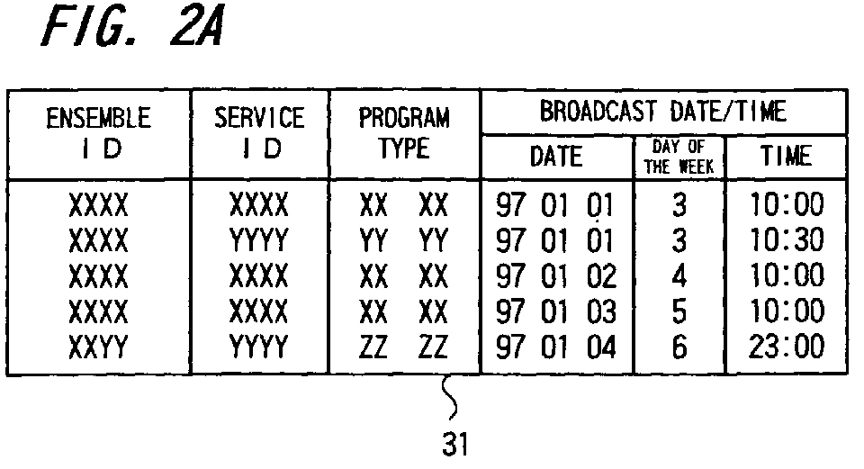
For example, data tables 31 to 33 as shown in FIG. 2
are provided in this memory 24. In this case, the data table 31
is to show a history of selecting services and therefore has
data columns of ensemble ID, service ID, program type and
broadcast date / time concerning programs selected in the past.
The data table 32 indicates selecting frequencies of programs
and has a data column of program type. Finally, the data table
33 is to show currently selectable services and as data columns
of ensemble ID, service ID and program type.
Every time when a program selection takes place, the
oldest data of the data table 31 is replaced with data of that
program and data of the date/time indicated by the clock circuit
25, thus causing the data table 31 to be renewed. Further,
according to data of the selected program, the data table 32 is
rearranged in the order of the frequencies of programs and the
data table 33 is also renewed.
In this arrangement, when a predetermined key of the
plurality of keys 21 is operated, as is shown in FIG. 4A, for
example, a menu showing program selecting modes is displayed on
LCD 23 and at the same time a cursor arrow mark 231 is displayed
at the head of the first item of the menu displayed. Then, when
a knob of the jog dial 22 is turned in a clockwise or
counterclockwise direction, the cursor arrow mark 231 moves
upward or downward between the items.
In this example, the following modes are prepared as
the program selecting modes.
In these selecting modes, the selection of a program
is performed as follows.
(1) Selecting mode according to the latest history
priority
Turning the jog dial 22 enables to move the cursor
arrow mark 231 in FIG. 4A in sequential manner. For example,
when making the cursor arrow mark 231 located at the first item
and pushing the jog dial 22 as it is, "Selecting mode according
to the latest history priority" of the first item will start.
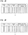
In this selecting mode, data of the data table 31 is
rearranged, as shown in FIG. 3A, for example, in order of
newness according to data of the broadcast date / time in a
manner that data of ensemble ID, service ID, program type and
broadcast date/time are combined as one set data.
Subsequently, it is checked whether or not a service
ID of the latest broadcast date / time, i. e. a service ID
coincident with the service ID "YYYY" in the first line of data
of the rearranged data table 31 (FIG. 3A) is found in the data
table 33 showing the currently selectable services in FIG. 2C.
In the present instance, it is not found. Thus, it is then
checked whether or not a service ID of the next latest broadcast
date / time, i.e. a service ID coincident with the service ID
"XXXX" in the second line of data of the data table 31 is found
in the data table 33.
In the present instance, because it is found in the
first line of the data table 33, selecting the program is
performed according to this service ID and thereafter the
selected state, i.e. received state of that program will
continue. At this time, as shown in FIG. 4B, for example, the
information on that selection is displayed in the LCD 23.
At that time, when the joy dial 22 is further turned,
e.g. in the clockwise direction, the selection of next candidate
will start. That is to say, it is checked whether or not a
service ID of the thirdly latest broadcast date/time,i.e. a
service ID coincident with the service ID "XXYY" in the third
line of data of the data table 31 is found in the data table 33.
In the present instance, because it is found in the second line
of the data table 33, selecting the program is performed
according to this service ID and thereafter the selected state
of that program will continue. This means that the program of
next candidate has been selected.
In this way, turning the jog dial 22 makes a program
of subsequent candidate to be selected in the same manner. If
there is no program for the candidate, the selection is then
performed returning to the initially selected program. Of
course, when the jog dial 22 is turned in the counterclockwise
direction, an operational opposite to that when turned in the
clockwise direction will be performed. In other words, a
previous candidate will be selected.
(2) Selecting made according to frequency order of
program type
After depressing a predetermined key 21, the jog dial
22 is turned to make the cursor arrow mark 231 located at the
second item in FIG. 4A. When the jog dial 22 is pushed as it
is, "Selecting mode according to frequency order of program
type" of the second item will start.
In this selecting mode, it is checked whether or not
a program type of the highest receiving frequency program, i.e.
a program type coincident with the program type "XXXX" in the
first line of data of the data table 32 (This is always
rearranged in frequency order.) is found in the data table 33
showing the currently selectable services. In the present
instance, because it is found in the first line of the data
table 33, selecting the program is performed according to this
service ID and thereafter the selected state of that program
will continue.
At this time, further turning the jog dial 22 in the
clockwise direction, an operation for selecting a next candidate
will start. That is to say, it is checked whether or not a
program type of the next highest receiving frequency program,
i.e. a program type coincident with the program type " YYYY" in
the second line of data of the data table 32 is found in the
data table 33. In the present instance, because it is found in
the second line of the data table 33, selecting the program is
performed according to this service ID and thereafter the
selected state of that program will continue. This means that
the program of next candidate has been selected. Of course, if
the jog dial 22 is turned in the counterclockwise direction, a
sequentially previous candidate, i.e. a sequentially higher
receiving frequency program will be selected.
Thus, by turning the jog dial 22, a program of
subsequent candidate is selected in the same manner. If there
is no program for the candidate, then the selection is performed
returning to the initially selected program.
(3) Selecting mode according to service priority during
the same time zone
After depressing a predetermined key 21, the jog dial
22 is turned to make the cursor arrow mark 231 located at the
third item in FIG. 4A. When the jog dial 22 is pushed as it is,
"Selecting mode according to service priority during the same
time zone" will start.
In this selecting mode, data of the data table 31 is
rearranged, as shown in FIG. 3B, for example, in a predetermined
order according to its broadcast date/time, in which the data of
ensemble ID, service ID, program type and broadcast date/ time
are combined as one set data. Here, in a column of day of the
week, 1 represents Monday, 2 represents Tuesday, 3 represents
Wednesday, 4 represents Thursday, 5 represents Friday, 6
represents Saturday, and 7 represents Sunday.
That is, FIG. 3B shows a result of the rearrangement
in a case where the present time is between ten and eleven
o'clock on Wednesday. This rearrangement is made in a manner
that data is arranged in order of day of the week giving a first
priority to the present day of the week. On the same day of the
week, it is arranged in order of time zone giving a first
priority to the present time zone. In this case, for example,
an exact ten o'clock and fifty-nine minutes after ten o'clock
are both handled as a time between ten and eleven o'clock. In
other words, a time pertinent to the same "hour" is handled as
the same time zone.
Subsequently, it is checked whether or not a service
ID coincident with a service ID "XXXX" in the first line of data
of the rearranged data table 31 (FIG. 3B) is found in the data
table 33 showing the currently selectable service. In the
present instance, because it is found in the first line of the
data table 33, selecting the program is performed according to
this service ID and thereafter the selected state of that
program will continue.
At this time, when the jog dial 22 is further turned
in the clockwise direction, selecting the next candidate will
start. That is to say, it is checked whether or not a service
ID coincident with a service ID "YYYY" in the second line of
data of the data table 31 is found in the data table 33. In the
present instance, because it is not found in the data table 33,
it is further checked whether or not a service ID coincident
with a service ID "XXYY" in the third line of data of the data
table 31 is found in the data table 33. In the present
instance, because it is coincident to the service ID in the
second line of the data table 33, selecting the program is
performed according to this service ID and thereafter the
selected state of that program will continue. This means that
the program of next candidate has been selected. Of course, if
the jog dial 22 is turned in the counterclockwise direction in a
condition that this next candidate is selected, the sequentially
previous candidate will be selected.
Thus, by operating to select the next candidate, a
program of subsequent candidate is selected in the same manner.
If there is no program for the candidate, the selection is then
performed returning to the first selected diagram.
As described above, the receiver of FIG. 1 is capable
of selecting a program in three kinds of selecting modes of (1)
to (3) items and in any mode it is arranged to select a program
itself based on the past receiving history, so that the
selection of a desired program is facilitated. Moreover, since
it is arranged to have a learning function, a user is able to
select his favorite programs without any need of complicated
settings.
A routine 100 shown in FIG. 5 is an example of
routines for implementing "Selecting mode according to the
latest history priority" of the aforesaid (1) item. For
example, as is shown in FIG. 4A, when the cursor arrow mark 231
is located at the position of selecting mode of (1) item, if the
jog dial 22 is pushed, processing by the CPU of the
microcomputer 20 will start from a step 101 of the routine 100.
In a next step 102, a pointer is set to the first line of data
lines of the data table 31 (FIG. 3A).
In the following step 111, a service ID coincident
with a service ID in the position of pointer set in the step 102
is retrieved from the data table 33.
The retrieved result is distinguished in a step 112.
If the coincident service ID is present, the processing will
then advance from the step 112 to a step 113. Then, in the step
113 selecting the program of the coincident service ID is
performed, and thereafter the routine 100 will end in a step
114.
If the coincident service ID is absent in the step
112, the processing will then advance from the step 112 to a
step 121. In the step 121, it is decided whether or not the
pointer set in the data table 31 is located at the lowest line
of the data table 31. If it is not located at the lowest line,
the processing will then advance from the step 121 to a step
122. In the step 122, the pointer is moved to the next line, in
the present instance, the second line of the data table 31 and
thereafter the processing will return to the step 111.
Thereafter, regarding a service ID of data lines
after the second line in the data table 31, the steps 111 to 122
are repeated until a service ID coincident with that service ID
is obtained from the data table 33. If the coincident service
ID is obtained, the program of that service ID will then be
selected by the step 113.
In addition, if the pointer is located at the lowest
line of the data table 31 in the step 121, the processing will
then advance from the step 121 to the step 114 where the routine
100 will end.
In this way, according to the routine 100, "Selecting
mode according to the latest history priority" of (1) item can
be implemented.
A routine 200 shown in FIG. 6A is an example of
routines for implementing "Selecting mode according to service
priority during the same time zone" of the aforesaid (3) item.
Particularly, when the cursor arrow mark 231 is located at the
position of selecting mode of (3) item, if the jog dial 22 is
pushed, processing by the CPU of the microcomputer 20 will start
from a step 201 and in a next step 202 data of the data table 31
is rearranged in order of time by comparing between "hours" of
time.
In the following step 203, a further rearrangement of
the rearranged data table 31 by the step 202 is performed giving
the priority to the present time and day of the week.
Thereafter, in a step 204, the resulting data table 31 in the
step 203 and the data table 33 are used for performing the same
processing as the routine 100 to select a broadcasting station,
and in a step 205 the routine 200 will end.
In this case, the step 203 can be constructed, for
example, as a routine 300. In the routine 300, processing will
start from a step 301 and in a next step 302 data of the present
time and day of the week are acquired from the clock circuit 25.
In the following step 303, a pointer is set to a data line of
the same "hour" as "hour" of the present time acquired by the
step 302 among data lines of the data table 31 (FIG. 3A).
Next, in a step 304, a data located between the first
line and the data line prior to the pointer set by the step 303
in data of the data table 31 is moved to the last rear part of
the data table 31. In a step 305, the processed data of the
data table 31 by the step 304 is rearranged, among data having
the same "hour" of time, in order of day of the week so that the
present day of the week acquired by the step 302 may be located
ahead. Thereafter, the routine 300 will end in a step 306.
Thus, according to the routines 200 and 300,
"Selecting mode according to serve priority during the same time
zone" of (3 ) item can be implemented.
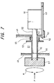
FIG. 7 and FIG. 8 show the jog dial 22 used for the
present embodiment. Specifically, a printed circuit board 43 is
fixed to the rear part of a chassis 41 (right side in the
figure). On the board 43 is mounted a rotary encoder 51 whose
input shaft (operating axis) 52 extends to be positioned at the
front side of the receiver through an aperture 42 in the chassis
41. Further, the input shaft 52 is made, e.g., hexagonal of its
section.
A joint 61 has a cylindrical portion 62 and a flange
portion 63 at an end of the cylindrical portion 62 which are
formed integrally by using metallic or plastic materials.
The cylindrical portion 62 is made, e.g. hexagonal of its
section. The input shaft 52 is inserted into the cylindrical
portion 62 in a condition that the flange portion 63 is directed
toward the rotary encoder 51.
Further, at the time, between the flange portion 63
and the chassis 41 is provided a coil spring 65 concentrically
with the input shaft 52, which biases the joint 61 in a
direction away from the rotary encoder 51. The cylindrical
portion 62 faces the front faces of a front panel 45 through an
aperture 46 of the panel 45. The tip of the cylindrical portion
is inserted into a hexagonal groove 67a provided in the rear
face of a knob 67 and is adhered and fixed thereto.
In addition, on the chassis 41 is provided a
microswitch 53, and an actuator (operating part) 56 of the
microswitch 53 is opposed to the flange portion 63.
In this arrangement, the knob 67 is fixed to the
cylindrical portion 62 of the joint 61. The cylindrical portion
62 is fit on the input shaft 52 of the rotary encoder 51 and
because both sections of the cylindrical portion 62 and the
input shaft 52 are made hexagonal, they are rotatively unified
and rotatable in a rotative direction R.
Accordingly, turning the knob 67 makes the input
shaft 52 to be turned together through the joint 61 and the
rotary encoder 51 will output a signal which varies depending on
the rotative direction and the rotative angle of the knob 67.
Therefore, by this signal it is possible to implement the
movement of the cursor arrow mark 231 and the change of the
selecting mode displayed on the LCD 23, as described above.
Moreover, since the knob 67 can be pushed along the
input shaft 52 in the direction of an arrow mark P against the
bias force of the coil spring 65, when the knob 67 is pushed in
the arrow mark direction P from a state of FIG. 7, the joint 61
will move in the P direction, i.e. the direction toward the
chassis 41 and then the flange portion 63 of the joint 61 pushes
the actuator 56 of the microswitch 53. Thus, pushing the knob
67 will cause a switching output from the microswitch 53 to be
obtained, thereby allowing the aforesaid decision of the
selecting mode, etc. to be performed. In this case, when the
pushing force to the knob 67 is removed, the joint 61, i.e. the
knob 67 will move in the direction opposite to the arrow mark P
direction by the bias force of the coil spring 65 and return to
the state of FIG. 7.
In this way, according to the jog dial 22, when the
knob 67 is turned in the arrow direction R, the selection of the
selecting mode can be performed, while when the knob 67 is
pushed in the P direction, the decision of the selecting mode
can be performed.
According to the present invention, because it is
arranged to select a program itself based on the past receiving
history, the selection of the desired program is made easier.
Also, because of its learning function, it is possible for a
user to select his favorite program without any need of
complicated settings.
Further, while the above embodiment is arranged to
perform the selection and decision of the selecting mode using
the jog dial 22, it is also possible to perform that by
operating keys.
EXPLANATION OF REFERENCE NUMERALS
- 10
- RECEIVING CIRCUIT
- 11
- ANTENNA
- 12
- TUNER CIRCUIT
- 13
- TRANSMISSION LINE DECODING CIRCUIT
- 14
- AUDIO DECODING CIRCUIT
- 15
- D/A CONVERTER
- 20
- MICROCOMPUTER
- 21
- OPERATION KEY
- 22
- JOG DIAL
- 23
- DISPLAY DEVICE
- 24
- MEMORY
- 25
- CLOCK CIRCUIT
- 31 TO 33
- DATA TABLES
- 51
- ROTARY ENCODER
- 67
- KNOB
- 100 TO 300
- ROUTINES