EP0866139A1 - Lance/burner for molten metal furnace - Google Patents
Lance/burner for molten metal furnace Download PDFInfo
- Publication number
- EP0866139A1 EP0866139A1 EP98104713A EP98104713A EP0866139A1 EP 0866139 A1 EP0866139 A1 EP 0866139A1 EP 98104713 A EP98104713 A EP 98104713A EP 98104713 A EP98104713 A EP 98104713A EP 0866139 A1 EP0866139 A1 EP 0866139A1
- Authority
- EP
- European Patent Office
- Prior art keywords
- furnace
- oxygen
- molten metal
- main gas
- bath
- Prior art date
- Legal status (The legal status is an assumption and is not a legal conclusion. Google has not performed a legal analysis and makes no representation as to the accuracy of the status listed.)
- Granted
Links
- 229910052751 metal Inorganic materials 0.000 title claims abstract description 78
- 239000002184 metal Substances 0.000 title claims abstract description 78
- QVGXLLKOCUKJST-UHFFFAOYSA-N atomic oxygen Chemical group [O] QVGXLLKOCUKJST-UHFFFAOYSA-N 0.000 claims abstract description 80
- 239000001301 oxygen Substances 0.000 claims abstract description 80
- 229910052760 oxygen Inorganic materials 0.000 claims abstract description 80
- 239000007789 gas Substances 0.000 claims abstract description 68
- 239000000446 fuel Substances 0.000 claims abstract description 25
- 238000000034 method Methods 0.000 claims abstract description 15
- 239000002893 slag Substances 0.000 claims description 18
- UGFAIRIUMAVXCW-UHFFFAOYSA-N Carbon monoxide Chemical compound [O+]#[C-] UGFAIRIUMAVXCW-UHFFFAOYSA-N 0.000 claims description 10
- 229910002091 carbon monoxide Inorganic materials 0.000 claims description 10
- OKTJSMMVPCPJKN-UHFFFAOYSA-N Carbon Chemical compound [C] OKTJSMMVPCPJKN-UHFFFAOYSA-N 0.000 claims description 8
- 229910052799 carbon Inorganic materials 0.000 claims description 8
- 239000000843 powder Substances 0.000 claims description 4
- 230000005587 bubbling Effects 0.000 claims 1
- 239000011261 inert gas Substances 0.000 claims 1
- 238000002347 injection Methods 0.000 abstract description 22
- 239000007924 injection Substances 0.000 abstract description 22
- 238000010891 electric arc Methods 0.000 abstract description 17
- 238000002485 combustion reaction Methods 0.000 abstract description 5
- 230000035515 penetration Effects 0.000 abstract description 2
- 239000012530 fluid Substances 0.000 description 8
- UQSXHKLRYXJYBZ-UHFFFAOYSA-N Iron oxide Chemical compound [Fe]=O UQSXHKLRYXJYBZ-UHFFFAOYSA-N 0.000 description 6
- 230000001427 coherent effect Effects 0.000 description 6
- 239000002737 fuel gas Substances 0.000 description 6
- VNWKTOKETHGBQD-UHFFFAOYSA-N methane Chemical group C VNWKTOKETHGBQD-UHFFFAOYSA-N 0.000 description 6
- 239000007800 oxidant agent Substances 0.000 description 5
- 230000001590 oxidative effect Effects 0.000 description 5
- VYPSYNLAJGMNEJ-UHFFFAOYSA-N Silicium dioxide Chemical compound O=[Si]=O VYPSYNLAJGMNEJ-UHFFFAOYSA-N 0.000 description 4
- 239000003153 chemical reaction reagent Substances 0.000 description 4
- 239000003517 fume Substances 0.000 description 4
- XEEYBQQBJWHFJM-UHFFFAOYSA-N Iron Chemical compound [Fe] XEEYBQQBJWHFJM-UHFFFAOYSA-N 0.000 description 3
- 230000004888 barrier function Effects 0.000 description 3
- 230000015572 biosynthetic process Effects 0.000 description 3
- 238000006243 chemical reaction Methods 0.000 description 3
- 239000003345 natural gas Substances 0.000 description 3
- 230000003647 oxidation Effects 0.000 description 3
- 238000007254 oxidation reaction Methods 0.000 description 3
- 239000007921 spray Substances 0.000 description 3
- CURLTUGMZLYLDI-UHFFFAOYSA-N Carbon dioxide Chemical compound O=C=O CURLTUGMZLYLDI-UHFFFAOYSA-N 0.000 description 2
- 235000008733 Citrus aurantifolia Nutrition 0.000 description 2
- MYMOFIZGZYHOMD-UHFFFAOYSA-N Dioxygen Chemical compound O=O MYMOFIZGZYHOMD-UHFFFAOYSA-N 0.000 description 2
- UFHFLCQGNIYNRP-UHFFFAOYSA-N Hydrogen Chemical compound [H][H] UFHFLCQGNIYNRP-UHFFFAOYSA-N 0.000 description 2
- 229910000831 Steel Inorganic materials 0.000 description 2
- 235000011941 Tilia x europaea Nutrition 0.000 description 2
- VXAUWWUXCIMFIM-UHFFFAOYSA-M aluminum;oxygen(2-);hydroxide Chemical compound [OH-].[O-2].[Al+3] VXAUWWUXCIMFIM-UHFFFAOYSA-M 0.000 description 2
- BRPQOXSCLDDYGP-UHFFFAOYSA-N calcium oxide Chemical compound [O-2].[Ca+2] BRPQOXSCLDDYGP-UHFFFAOYSA-N 0.000 description 2
- 239000000292 calcium oxide Substances 0.000 description 2
- ODINCKMPIJJUCX-UHFFFAOYSA-N calcium oxide Inorganic materials [Ca]=O ODINCKMPIJJUCX-UHFFFAOYSA-N 0.000 description 2
- 230000002939 deleterious effect Effects 0.000 description 2
- 239000001257 hydrogen Substances 0.000 description 2
- 229910052739 hydrogen Inorganic materials 0.000 description 2
- 239000004571 lime Substances 0.000 description 2
- 239000000395 magnesium oxide Substances 0.000 description 2
- CPLXHLVBOLITMK-UHFFFAOYSA-N magnesium oxide Inorganic materials [Mg]=O CPLXHLVBOLITMK-UHFFFAOYSA-N 0.000 description 2
- AXZKOIWUVFPNLO-UHFFFAOYSA-N magnesium;oxygen(2-) Chemical compound [O-2].[Mg+2] AXZKOIWUVFPNLO-UHFFFAOYSA-N 0.000 description 2
- 238000002844 melting Methods 0.000 description 2
- 230000008018 melting Effects 0.000 description 2
- 239000000203 mixture Substances 0.000 description 2
- 239000003923 scrap metal Substances 0.000 description 2
- 239000000377 silicon dioxide Substances 0.000 description 2
- 235000012239 silicon dioxide Nutrition 0.000 description 2
- 239000007787 solid Substances 0.000 description 2
- 239000010959 steel Substances 0.000 description 2
- XLYOFNOQVPJJNP-UHFFFAOYSA-N water Substances O XLYOFNOQVPJJNP-UHFFFAOYSA-N 0.000 description 2
- 238000007792 addition Methods 0.000 description 1
- 239000000654 additive Substances 0.000 description 1
- 239000000956 alloy Substances 0.000 description 1
- 229910045601 alloy Inorganic materials 0.000 description 1
- 238000005275 alloying Methods 0.000 description 1
- 239000001569 carbon dioxide Substances 0.000 description 1
- 229910002092 carbon dioxide Inorganic materials 0.000 description 1
- 238000009841 combustion method Methods 0.000 description 1
- 239000000470 constituent Substances 0.000 description 1
- 238000000354 decomposition reaction Methods 0.000 description 1
- 229910001882 dioxygen Inorganic materials 0.000 description 1
- 239000000428 dust Substances 0.000 description 1
- 239000006260 foam Substances 0.000 description 1
- 229930195733 hydrocarbon Natural products 0.000 description 1
- 150000002430 hydrocarbons Chemical class 0.000 description 1
- 229910052742 iron Inorganic materials 0.000 description 1
- 239000007788 liquid Substances 0.000 description 1
- 238000003756 stirring Methods 0.000 description 1
Images


Classifications
-
- F—MECHANICAL ENGINEERING; LIGHTING; HEATING; WEAPONS; BLASTING
- F27—FURNACES; KILNS; OVENS; RETORTS
- F27B—FURNACES, KILNS, OVENS OR RETORTS IN GENERAL; OPEN SINTERING OR LIKE APPARATUS
- F27B3/00—Hearth-type furnaces, e.g. of reverberatory type; Electric arc furnaces ; Tank furnaces
- F27B3/10—Details, accessories or equipment, e.g. dust-collectors, specially adapted for hearth-type furnaces
- F27B3/22—Arrangements of air or gas supply devices
- F27B3/225—Oxygen blowing
-
- C—CHEMISTRY; METALLURGY
- C21—METALLURGY OF IRON
- C21C—PROCESSING OF PIG-IRON, e.g. REFINING, MANUFACTURE OF WROUGHT-IRON OR STEEL; TREATMENT IN MOLTEN STATE OF FERROUS ALLOYS
- C21C5/00—Manufacture of carbon-steel, e.g. plain mild steel, medium carbon steel or cast steel or stainless steel
- C21C5/52—Manufacture of steel in electric furnaces
-
- C—CHEMISTRY; METALLURGY
- C21—METALLURGY OF IRON
- C21C—PROCESSING OF PIG-IRON, e.g. REFINING, MANUFACTURE OF WROUGHT-IRON OR STEEL; TREATMENT IN MOLTEN STATE OF FERROUS ALLOYS
- C21C5/00—Manufacture of carbon-steel, e.g. plain mild steel, medium carbon steel or cast steel or stainless steel
- C21C5/28—Manufacture of steel in the converter
- C21C5/42—Constructional features of converters
- C21C5/46—Details or accessories
-
- C—CHEMISTRY; METALLURGY
- C21—METALLURGY OF IRON
- C21C—PROCESSING OF PIG-IRON, e.g. REFINING, MANUFACTURE OF WROUGHT-IRON OR STEEL; TREATMENT IN MOLTEN STATE OF FERROUS ALLOYS
- C21C5/00—Manufacture of carbon-steel, e.g. plain mild steel, medium carbon steel or cast steel or stainless steel
- C21C5/52—Manufacture of steel in electric furnaces
- C21C5/5211—Manufacture of steel in electric furnaces in an alternating current [AC] electric arc furnace
- C21C5/5217—Manufacture of steel in electric furnaces in an alternating current [AC] electric arc furnace equipped with burners or devices for injecting gas, i.e. oxygen, or pulverulent materials into the furnace
-
- C—CHEMISTRY; METALLURGY
- C21—METALLURGY OF IRON
- C21C—PROCESSING OF PIG-IRON, e.g. REFINING, MANUFACTURE OF WROUGHT-IRON OR STEEL; TREATMENT IN MOLTEN STATE OF FERROUS ALLOYS
- C21C5/00—Manufacture of carbon-steel, e.g. plain mild steel, medium carbon steel or cast steel or stainless steel
- C21C5/28—Manufacture of steel in the converter
- C21C5/42—Constructional features of converters
- C21C5/46—Details or accessories
- C21C5/4606—Lances or injectors
- C21C5/4613—Refractory coated lances; Immersion lances
-
- Y—GENERAL TAGGING OF NEW TECHNOLOGICAL DEVELOPMENTS; GENERAL TAGGING OF CROSS-SECTIONAL TECHNOLOGIES SPANNING OVER SEVERAL SECTIONS OF THE IPC; TECHNICAL SUBJECTS COVERED BY FORMER USPC CROSS-REFERENCE ART COLLECTIONS [XRACs] AND DIGESTS
- Y02—TECHNOLOGIES OR APPLICATIONS FOR MITIGATION OR ADAPTATION AGAINST CLIMATE CHANGE
- Y02P—CLIMATE CHANGE MITIGATION TECHNOLOGIES IN THE PRODUCTION OR PROCESSING OF GOODS
- Y02P10/00—Technologies related to metal processing
- Y02P10/20—Recycling
Definitions
- This invention relates generally to injecting gas such as oxygen into a furnace containing a pool of molten metal and is particularly advantageous for use in an electric arc furnace.
- a method for providing gas into a furnace containing a bath which is comprised of a pool of molten metal with a layer of slag on its top surface comprising:
- oxygen means a fluid having an oxygen concentration which exceeds that of air, preferably having an oxygen concentration of at least 30 mole percent, most preferably at least 80 mole percent. Oxygen may be commercially pure oxygen having an oxygen concentration of 99.5 mole percent or more.
- flame envelope means a combusting stream substantially coaxial with the main gas stream and annular thereto.
- slag means a molten or solid layer of oxides generally comprising one or more of calcium oxide, silicon dioxide, magnesium oxide, aluminum dioxide and iron oxide.
- froamy slag means a slag which also contains a high volume fraction of gas bubbles such as carbon monoxide which greatly reduces the density of the slag layer and imparts a foam like appearance and behavior to the slag layer.
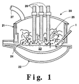
- Figure 1 is an elevation view partly in cross section of an embodiment of the lance/burner of this invention in operation in an electric arc furnace.
- Figures 2 and 3 are detailed views of one embodiment, Figure 2 being a cross sectional view and Figure 3 being a head-on view, of the injection end of the lance/burner useful in the practice of this invention.
- Figure 4 is a representation of a preferred embodiment of the gas streams emitted from the lance/burner and of the flame envelope formed around the main gas stream in the practice of this invention.
- the invention comprises the creation and use of a jet of high velocity main gas such as oxygen which is maintained coherent by a flame envelope around the high velocity jet.
- the coherency of the jet enables the injection point of the jet into the furnace to be placed a significant distance above the surface of the molten metal pool while still enabling the jet to penetrate the surface of the molten metal pool so that the high velocity main gas can pass into the molten metal pool.
- the flame envelope is formed by combusting fluid, preferably injected into the furnace in two fluid streams which are each annularly coaxial with the high velocity gas stream. One of the fluid streams is a fuel stream and the other is a secondary oxygen stream.
- the slower moving flame envelope resulting from the combustion of the two annular streams forms a fluid shield or barrier around the high velocity gas stream greatly reducing gases from outside the high velocity gas stream being entrained into the high velocity gas stream.
- gases are entrained into the high velocity stream causing it to expand in a characteristic cone pattern.
- the flame envelope barrier By action of the flame envelope barrier, this entrainment is greatly reduced for a significant distance from the point of injection into the furnace, and the high velocity gas jet substantially retains its original diameter through this distance, i.e. is coherent through this distance.
- the jet may contain powder or other additives which may be injected into the molten metal with the main gas.
- a particularly advantageous application of this invention is its use in an electric arc furnace.
- the main gas jet comprises oxygen which reacts with carbon in the molten metal to form carbon monoxide which bubbles out of the molten metal.
- Post combustion oxygen reacts with this carbon monoxide above the surface of the molten metal pool providing additional heat into the furnace improving energy efficiency and productivity and reducing the level of deleterious carbon monoxide which is emitted into the atmosphere from the furnace.
- lance 1 having a central conduit 2, a first annular passageway 3 and a second annular passageway 4, each of the annular passageways being coaxial with central conduit 2.
- Central conduit 2 terminates at injection end 5 of lance 1 to form main orifice 6.
- the first and second annular passageways also terminate at the injection end, preferably, as illustrated in the Figures, in substantially the same plane as main orifice 6.
- the first and second annular passageways may each form annular orifices around main orifice 6.
- first annular passageway 3 terminates at injection end 5 in a set of first injection holes 7 arranged in a circle around main orifice 6, and second annular passageway 4 terminates at injection end 5 in a set of second injection holes 8 arranged in a circle around main orifice 6 and first injection holes 7.
- Each of central conduit 2 and second annular passageway 4 communicate with a source of oxygen (not shown).
- the oxygen used in central conduit 2 and second annular passageway 4 may be the same oxygen fluid, or a different oxygen fluid may be used in second annular passageway 4 from that used in central conduit 2.
- First annular passageway 3 communicates with a source of fuel (not shown).
- the fuel may be any fuel, preferably is a gaseous fuel and most preferably is natural gas or hydrogen.
- the fuel may be passed through the lance in the outermost annular passageway and the secondary oxygen may be passed through the lance in the inner annular passageway.
- the fuel and secondary oxidant may be passed through the lance as a mixture through one annular passageway.
- FIG. 1 there is shown electric arc furnace 20 having sidewall 21 and bottom wall 22 and containing a bath comprising a pool of molten metal 23.
- the metal will comprise iron or steel.
- a slag layer 24 which may be molten or solid, above the pool of molten metal and a layer of scrap metal 25 above slag layer 24.
- the slag layer generally comprises one or more of calcium oxide, silicon dioxide, magnesium oxide, aluminum dioxide and iron oxide.
- the scrap layer if present, is melted by heat provided by electrodes 26 to form molten metal pool 23.
- the molten metal pool comprises, in addition to metal, oxidizeable matter such as carbon and/or hydrocarbons.
- Lance/burner 1 is positioned so as to pass through sidewall 21 with its injection end 5 above and spaced from the top surface of the bath by a distance along the jet axis of at least 20d, and may be spaced from the bath by a distance along the jet axis of up to 100d or more, where d is the exit diameter of the nozzle through which the main gas is ejected out from the lance/burner.
- the jet axis is the imaginary line running through the center of the jet along its length. Typically this spacing along the jet axis is within the range of from 30d to 60d.
- Figure 1 shows one lance used with the furnace. In commercial practice it may be preferable to use more than one lance.
- Main oxygen is injected into furnace 20 through nozzle orifice 6 of lance 1 toward the bath comprising molten metal pool 23 at an initial jet axis velocity, generally at least 1000 feet per second (fps) and preferably at least 1500 fps, to form a high velocity main oxygen stream 30 as illustrated in Figure 4.
- the jet axis velocity is the velocity of the gas stream at its jet axis.
- the main oxygen will contact the bath at a velocity of at least 50 percent, preferably at least 75 percent of the initial jet axis velocity of the main oxygen stream.
- the main oxygen has a supersonic velocity upon ejection from the lance and also has a supersonic velocity when it contacts the bath.
- fuel is injected into furnace 20 through first injection holes 7 and secondary oxygen is injected into furnace 20 through second injection holes 8 to form a fuel stream and a secondary oxygen stream, each of these streams being concentric to and coaxial with stream 30.
- Secondary oxygen combusts with fuel to form flame envelope 33 which has a velocity which is less than that of main oxygen stream 30 and generally is within the range of from 50 to 500 fps.
- the flame envelope forms at or very close, e.g. within one inch, to the lance tip and extends substantially, i.e. at least 75 percent of, the entire length of the main gas stream within the furnace to the bath.
- the flame envelope extends the entire length of the main gas stream within the furnace to the bath.
- Flame envelope 33 forms a barrier or shield around oxygen stream 30 thereby greatly reducing the amount of gas outside of stream 30 from being entrained into stream 30.
- stream 30 does not significantly expand from the point where it is injected into the furnace through lance 1 to the point where it impacts the bath comprising molten metal pool 23.
- the diameter of stream 30 when it impacts the bath comprising molten metal pool 23 will be essentially the same as that when it is injected into furnace 20 through lance 1.
- the injection end of the lance may be a large distance from the molten metal while still enabling the high velocity oxygen stream 30 to impact the molten metal pool surface with enough force so that the high velocity oxygen stream penetrates the bath surface and passes into the molten metal pool.
- the main oxygen in high velocity stream 30 reacts with oxidizeable matter within the molten metal pool.
- the main oxygen may react with carbon in the molten metal pool to generate carbon monoxide in an exothermic reaction which provides additional heat to the furnace and stirs the molten metal to improve heat transfer.
- Gas generated by the reaction of main oxygen with oxidizeable matter within the molten metal pool bubbles up out of the molten metal pool.
- gas or gases are in the form of incompletely combusted species, such as the aforesaid carbon monoxide.
- Such incompletely combusted species are environmentally deleterious and also represent an energy loss if allowed to pass unreacted out of the furnace.
- Post combustion oxygen provided into the furnace above the molten metal reacts with these incompletely combusted species as was previously described.
- the amount of fuel and secondary oxidant used in the lance mode, is not significantly greater than that required to form the flame envelope.
- it may be desirable to provide a large amount of heat into the furnace such as, for example, to melt scrap in the furnace.
- a high flowrate of oxidant may be provided into the furnace and the fuel and oxidant, which may be secondary and/or main oxidant, is used to combust the fuel in order to generate heat for the furnace.
- the lance used in the practice of this invention may, if desired, also function as a burner i.e., in the lance/burner mode.
- the flame can melt any scrap that may fall in front of the burner due to progression of scrap melting and cave-ins, thereby maintaining this passageway for bath lancing.
- the high natural gas flow rate can also provide a blanket of fuel gas around the coherent jet as it penetrates the molten metal bath. When the coherent jet penetrates the metal bath, a small localized cavity is formed and there is little deflection of the gas stream and little bath splashing. However, some spray may occur above the bath. The spray will be contained in a fuel gas blanket.
- the lance/burner of the invention may also function solely as a burner during times when high velocity gas injection into the molten metal is not desired.
- oxygen was injected into a molten metal bath.
- the oxygen was ejected from the lance tip through a nozzle having an exit diameter of 0.807 inch.
- the lance tip was positioned 28 inches above the surface of the bath and at a 40 degree angle to the horizontal so that the oxygen jet passed through a distance of 43 inches or 53 nozzle diameters from the lance tip to the bath surface.
- the main oxygen gas was enveloped in a flame envelope from the lance tip to the bath surface and had an initial jet axis velocity of 1600 fps and maintained this jet axis velocity of 1600 fps when it impacted the bath surface.
Landscapes
- Engineering & Computer Science (AREA)
- Chemical & Material Sciences (AREA)
- Manufacturing & Machinery (AREA)
- Materials Engineering (AREA)
- Metallurgy (AREA)
- Organic Chemistry (AREA)
- Mechanical Engineering (AREA)
- General Engineering & Computer Science (AREA)
- Vertical, Hearth, Or Arc Furnaces (AREA)
- Refinement Of Pig-Iron, Manufacture Of Cast Iron, And Steel Manufacture Other Than In Revolving Furnaces (AREA)
- Furnace Charging Or Discharging (AREA)
- Treatment Of Steel In Its Molten State (AREA)
- Furnace Details (AREA)
Abstract
Description
Claims (10)
- A method for providing gas into a furnace containing a bath which is comprised of a pool of molten metal with a layer of slag on its top surface, said method comprising:(A) injecting a high velocity main gas stream into the furnace above the bath and injecting into the furnace fuel and secondary oxygen coaxially with the high velocity main gas stream;(B) combusting fuel with secondary oxygen to form a flame envelope around the high velocity main gas stream; and(C) passing the high velocity main gas stream into the bath wherein the flame envelope extends substantially the entire length of the main gas stream within the furnace to the bath.
- The method of claim 1 wherein the main gas comprises oxygen.
- The method of claim 2 wherein the pool of molten metal contains carbon and further comprising reacting main oxygen with carbon within the molten metal pool to form carbon monoxide, bubbling carbon monoxide out of the molten metal pool and injecting additional oxygen into the furnace above the molten metal pool to oxidize the carbon monoxide that bubbles out of the molten metal pool.
- The method of claim 1 wherein the fuel and secondary oxygen are injected into the furnace in two streams, each of said two streams being concentric with the high velocity main gas stream.
- The method of claim 1 wherein the main gas stream comprises an inert gas.
- The method of claim 1 wherein some of the fuel does not combust and is passed into the slag layer wherein it reacts to form gas which serves to create a foamy slag layer.
- The method of claim 1 wherein the flame envelope extends the entire length of the main gas stream within the furnace to the bath.
- The method of claim 1 wherein the main gas stream passed into the molten metal pool contains powder.
- The method of claim 2 wherein the secondary oxygen is injected into the furnace at a flowrate which is within the range of from 25 to 75 percent of the total oxygen flowrate of the secondary oxygen and main gas oxygen injected into the furnace, and said total oxygen flowrate is within the range of 100 to 150 percent of that required to combust stoichiometrically with the fuel injected into the furnace.
- The method of claim 2 wherein the main gas oxygen is injected into the furnace at a flowrate which is within the range of from 75 to 99 percent of the total oxygen flowrate of the secondary oxygen and main gas oxygen injected into the furnace, and said total oxygen flowrate is greater than 100 percent of that required to combust stoichiometrically with the fuel injected into the furnace.
Applications Claiming Priority (2)
| Application Number | Priority Date | Filing Date | Title |
|---|---|---|---|
| US81981297A | 1997-03-18 | 1997-03-18 | |
| US819812 | 1997-03-18 |
Publications (2)
| Publication Number | Publication Date |
|---|---|
| EP0866139A1 true EP0866139A1 (en) | 1998-09-23 |
| EP0866139B1 EP0866139B1 (en) | 2002-07-03 |
Family
ID=25229145
Family Applications (1)
| Application Number | Title | Priority Date | Filing Date |
|---|---|---|---|
| EP98104713A Revoked EP0866139B1 (en) | 1997-03-18 | 1998-03-16 | Method using a burner/lance for injecting gas into molten metal |
Country Status (11)
| Country | Link |
|---|---|
| US (1) | US6125133A (en) |
| EP (1) | EP0866139B1 (en) |
| JP (1) | JP3774319B2 (en) |
| KR (1) | KR100368518B1 (en) |
| CN (1) | CN1140760C (en) |
| BR (1) | BR9800905A (en) |
| CA (1) | CA2232219C (en) |
| DE (1) | DE69806290T2 (en) |
| ES (1) | ES2175544T3 (en) |
| ID (1) | ID20060A (en) |
| ZA (1) | ZA987865B (en) |
Cited By (19)
| Publication number | Priority date | Publication date | Assignee | Title |
|---|---|---|---|---|
| US6139310A (en) * | 1999-11-16 | 2000-10-31 | Praxair Technology, Inc. | System for producing a single coherent jet |
| US6142764A (en) * | 1999-09-02 | 2000-11-07 | Praxair Technology, Inc. | Method for changing the length of a coherent jet |
| FR2797738A1 (en) * | 1999-08-18 | 2001-02-23 | Air Liquide | Electric arc furnace supersonic gas injection process, especially for oxygen injection into a steel-making arc furnace, uses a surrounding gas jet to protect the supersonic gas jet against the ambient atmosphere |
| US6241510B1 (en) | 2000-02-02 | 2001-06-05 | Praxair Technology, Inc. | System for providing proximate turbulent and coherent gas jets |
| US6261338B1 (en) | 1999-10-12 | 2001-07-17 | Praxair Technology, Inc. | Gas and powder delivery system and method of use |
| US6334976B1 (en) | 2000-08-03 | 2002-01-01 | Praxair Technology, Inc. | Fluid cooled coherent jet lance |
| EP1138638A3 (en) * | 2000-03-29 | 2002-01-02 | The Boc Group, Inc. | Burner and combustion method |
| EP1179602A1 (en) * | 2000-08-07 | 2002-02-13 | L'air Liquide, Societe Anonyme Pour L'etude Et L'exploitation Des Procedes Georges Claude | Method for injection of a gas with an injection nozzle |
| FR2816324A1 (en) * | 2000-11-09 | 2002-05-10 | Air Liquide | Method for the supersonic injection of gas into a liquid using an injector incorporating a Laval tuyere with dimensions calculated as a function of flow rate and jet speed |
| FR2822939A1 (en) * | 2001-03-29 | 2002-10-04 | Air Liquide | Injection of oxygen into a furnace involves using a central jet of oxygen at a first injection speed surrounded by a peripheral sheath of oxygen injected at a lower speed |
| EP1258534A1 (en) * | 2001-05-18 | 2002-11-20 | Praxair Technology, Inc. | Quadrilateral assembly for coherent jet lancing and post combustion in an electric arc furnace |
| WO2003097882A1 (en) * | 2002-05-15 | 2003-11-27 | Hatch Ltd. | Continuous steelmaking process in an eaf and plant slag composition for use therein |
| WO2003104508A1 (en) * | 2002-06-11 | 2003-12-18 | The Boc Group Plc | Refining ferroalloys |
| WO2006131764A1 (en) * | 2005-06-10 | 2006-12-14 | The Boc Group Plc | Manufacture of ferroalloys |
| WO2008076901A1 (en) * | 2006-12-15 | 2008-06-26 | Praxair Technology, Inc. | Injection method for inert gas |
| US7591876B2 (en) | 2002-04-24 | 2009-09-22 | The Boc Group Plc | Injection of solids into liquids by means of a shrouded supersonic gas jet |
| WO2016008864A1 (en) * | 2014-07-15 | 2016-01-21 | Primetals Technologies Germany Gmbh | Electric arc furnace comprising a safety device, and a method for protecting peripheral devices on electric arc furnaces |
| EP2102614B2 (en) † | 2006-12-27 | 2017-06-14 | Danieli & C. Officine Meccaniche SpA | Device and method for measuring the temperature of the liquid metal in an electric furnace |
| CN114616349A (en) * | 2019-11-06 | 2022-06-10 | 杰富意钢铁株式会社 | Method for manufacturing molten iron based on electric furnace |
Families Citing this family (30)
| Publication number | Priority date | Publication date | Assignee | Title |
|---|---|---|---|---|
| US6432163B1 (en) * | 2001-06-22 | 2002-08-13 | Praxair Technology, Inc. | Metal refining method using differing refining oxygen sequence |
| US6450799B1 (en) | 2001-12-04 | 2002-09-17 | Praxair Technology, Inc. | Coherent jet system using liquid fuel flame shroud |
| JP3864092B2 (en) * | 2002-01-10 | 2006-12-27 | 東京瓦斯株式会社 | Flame retardant decomposition burner |
| US6773484B2 (en) * | 2002-06-26 | 2004-08-10 | Praxair Technology, Inc. | Extensionless coherent jet system with aligned flame envelope ports |
| US20050145071A1 (en) * | 2003-03-14 | 2005-07-07 | Cates Larry E. | System for optically analyzing a molten metal bath |
| US20040178545A1 (en) * | 2003-03-14 | 2004-09-16 | Cates Larry E. | System for optically analyzing a molten metal bath |
| US6932854B2 (en) * | 2004-01-23 | 2005-08-23 | Praxair Technology, Inc. | Method for producing low carbon steel |
| WO2005079431A2 (en) * | 2004-02-16 | 2005-09-01 | Measurement Technology Laboratories Corporation | Particulate filter and method of use |
| EP1749109B1 (en) * | 2004-05-14 | 2009-07-22 | Linde, Inc. | Refining molten metal |
| US7438848B2 (en) * | 2004-06-30 | 2008-10-21 | The Boc Group, Inc. | Metallurgical lance |
| ITMI20050241A1 (en) * | 2005-02-18 | 2006-08-19 | Techint Spa | MULTIFUNCTIONAL INJECTOR AND ITS COMBUSTION PROCEDURE FOR METALLURGICAL TREATMENT IN AN ELECTRIC ARC FURNACE |
| US7297180B2 (en) * | 2005-07-13 | 2007-11-20 | Praxair Technology, Inc. | Method for operating a vacuum vessel with a coherent jet |
| US8696348B2 (en) * | 2006-04-26 | 2014-04-15 | Air Products And Chemicals, Inc. | Ultra-low NOx burner assembly |
| US7452401B2 (en) * | 2006-06-28 | 2008-11-18 | Praxair Technology, Inc. | Oxygen injection method |
| EP2080972A1 (en) * | 2008-01-08 | 2009-07-22 | L'AIR LIQUIDE, Société Anonyme pour l'Etude et l'Exploitation des Procédés Georges Claude | Combined burner and lance apparatus for electric arc furnaces |
| US8202470B2 (en) * | 2009-03-24 | 2012-06-19 | Fives North American Combustion, Inc. | Low NOx fuel injection for an indurating furnace |
| US8142711B2 (en) * | 2009-04-02 | 2012-03-27 | Nu-Core, Inc. | Forged copper burner enclosure |
| US8377372B2 (en) * | 2009-11-30 | 2013-02-19 | L'air Liquide Societe Anonyme Pour L'etude Et L'exploitation Des Procedes Georges Claude | Dynamic lances utilizing fluidic techniques |
| US20110127701A1 (en) * | 2009-11-30 | 2011-06-02 | Grant Michael G K | Dynamic control of lance utilizing co-flow fluidic techniques |
| US8323558B2 (en) * | 2009-11-30 | 2012-12-04 | L'air Liquide Societe Anonyme Pour L'etude Et L'exploitation Des Procedes Georges Claude | Dynamic control of lance utilizing counterflow fluidic techniques |
| US8992656B2 (en) * | 2011-12-21 | 2015-03-31 | Praxair Technology, Inc. | Controllable solids injection |
| US10215494B2 (en) | 2014-11-05 | 2019-02-26 | Daido Steel Co., Ltd. | Method of operating electric arc furnace |
| US10234206B2 (en) | 2014-11-05 | 2019-03-19 | Daido Steel Co., Ltd. | Electric arc furnace |
| FR3037059B1 (en) * | 2015-06-02 | 2017-06-16 | Saint-Gobain Emballage | SONIC INJECTION OVEN |
| CN106500514B (en) * | 2016-10-19 | 2019-03-12 | 嘉峪关宏电铁合金有限责任公司 | A method of preventing electrodes in mine hot stove deflection |
| CN109628689B (en) * | 2019-02-27 | 2020-12-04 | 中冶赛迪工程技术股份有限公司 | Oxygen supply method of high-speed iron water ratio electric furnace |
| JP7091386B2 (en) * | 2020-04-27 | 2022-06-27 | 大陽日酸株式会社 | Oxygen burner |
| DE102020215147A1 (en) | 2020-12-01 | 2022-06-02 | Sms Group Gmbh | Process for the pyrometallurgical melting down of raw materials containing metal, residues and/or secondary residues |
| DE102020215140A1 (en) * | 2020-12-01 | 2022-06-02 | Sms Group Gmbh | Process and melting unit for pyrometallurgical melting of raw materials containing metal, residues and/or secondary residues |
| KR20250081332A (en) * | 2023-11-29 | 2025-06-05 | 주식회사 포스코 | Structure of fine material charging for electric smelting furnace |
Citations (6)
| Publication number | Priority date | Publication date | Assignee | Title |
|---|---|---|---|---|
| GB1072121A (en) * | 1964-02-07 | 1967-06-14 | British Oxygen Co Ltd | Treatment of metal |
| US3729285A (en) * | 1972-05-22 | 1973-04-24 | G Schwedersky | Burner and method of operating it to control the production of nitrogen oxides |
| DE3509795C1 (en) * | 1985-03-19 | 1986-06-05 | Klöckner CRA Technologie GmbH, 4100 Duisburg | Water-cooled blowing lance for blowing oxygen onto a molten metal |
| US4622007A (en) * | 1984-08-17 | 1986-11-11 | American Combustion, Inc. | Variable heat generating method and apparatus |
| FR2644558A1 (en) * | 1989-03-16 | 1990-09-21 | Air Liquide | Arc furnace equipped with fuel oil/oxygen burners and fuel oil/oxygen burner |
| WO1996006954A1 (en) * | 1994-08-29 | 1996-03-07 | American Combustion, Incorporated | Method and apparatus for electric steelmaking |
Family Cites Families (17)
| Publication number | Priority date | Publication date | Assignee | Title |
|---|---|---|---|---|
| US33464A (en) * | 1861-10-08 | Bradley w | ||
| US3216714A (en) * | 1963-02-04 | 1965-11-09 | Bot Brassert Oxygen Technik Ag | Heating and blowing device for metallurgical purposes |
| FR1424029A (en) * | 1964-01-06 | 1966-01-07 | Union Carbide Corp | Method and apparatus for introducing a stream of process gas into a bath of molten metal |
| US4373949A (en) * | 1979-02-07 | 1983-02-15 | Union Carbide Corporation | Method for increasing vessel lining life for basic oxygen furnaces |
| US4210442A (en) * | 1979-02-07 | 1980-07-01 | Union Carbide Corporation | Argon in the basic oxygen process to control slopping |
| JPS5687617A (en) * | 1979-12-19 | 1981-07-16 | Daido Steel Co Ltd | Steel making method using arc furnace |
| AT372110B (en) * | 1981-12-23 | 1983-09-12 | Voest Alpine Ag | DEVICE FOR PRODUCING STEEL |
| US4923391A (en) * | 1984-08-17 | 1990-05-08 | American Combustion, Inc. | Regenerative burner |
| US4642047A (en) * | 1984-08-17 | 1987-02-10 | American Combustion, Inc. | Method and apparatus for flame generation and utilization of the combustion products for heating, melting and refining |
| CN1007920B (en) * | 1985-07-15 | 1990-05-09 | 美国氧化公司 | Method and apparatus for flame generation |
| DE3629055A1 (en) * | 1986-08-27 | 1988-03-03 | Kloeckner Cra Tech | METHOD FOR INCREASING ENERGY IN ELECTRIC ARC FURNACES |
| US4752330A (en) * | 1986-11-21 | 1988-06-21 | American Combustion, Inc. | Method for melting and refining metals |
| US4890562A (en) * | 1988-05-26 | 1990-01-02 | American Combustion, Inc. | Method and apparatus for treating solid particles |
| US5471495A (en) * | 1991-11-18 | 1995-11-28 | Voest-Alpine Industrieanlagenbeau Gmbh | Electric arc furnace arrangement for producing steel |
| US5377960A (en) * | 1993-03-01 | 1995-01-03 | Berry Metal Company | Oxygen/carbon blowing lance assembly |
| US5572544A (en) * | 1994-07-21 | 1996-11-05 | Praxair Technology, Inc. | Electric arc furnace post combustion method |
| US5714113A (en) * | 1994-08-29 | 1998-02-03 | American Combustion, Inc. | Apparatus for electric steelmaking |
-
1997
- 1997-03-18 US US08/819,812 patent/US6125133A/en not_active Expired - Fee Related
-
1998
- 1998-03-12 ID IDP980362A patent/ID20060A/en unknown
- 1998-03-16 KR KR10-1998-0008699A patent/KR100368518B1/en not_active Expired - Fee Related
- 1998-03-16 ES ES98104713T patent/ES2175544T3/en not_active Expired - Lifetime
- 1998-03-16 JP JP08242798A patent/JP3774319B2/en not_active Expired - Fee Related
- 1998-03-16 DE DE69806290T patent/DE69806290T2/en not_active Revoked
- 1998-03-16 CN CNB981041825A patent/CN1140760C/en not_active Expired - Fee Related
- 1998-03-16 EP EP98104713A patent/EP0866139B1/en not_active Revoked
- 1998-03-16 BR BR9800905-2A patent/BR9800905A/en not_active IP Right Cessation
- 1998-03-16 CA CA002232219A patent/CA2232219C/en not_active Expired - Lifetime
- 1998-08-28 ZA ZA987865A patent/ZA987865B/en unknown
Patent Citations (6)
| Publication number | Priority date | Publication date | Assignee | Title |
|---|---|---|---|---|
| GB1072121A (en) * | 1964-02-07 | 1967-06-14 | British Oxygen Co Ltd | Treatment of metal |
| US3729285A (en) * | 1972-05-22 | 1973-04-24 | G Schwedersky | Burner and method of operating it to control the production of nitrogen oxides |
| US4622007A (en) * | 1984-08-17 | 1986-11-11 | American Combustion, Inc. | Variable heat generating method and apparatus |
| DE3509795C1 (en) * | 1985-03-19 | 1986-06-05 | Klöckner CRA Technologie GmbH, 4100 Duisburg | Water-cooled blowing lance for blowing oxygen onto a molten metal |
| FR2644558A1 (en) * | 1989-03-16 | 1990-09-21 | Air Liquide | Arc furnace equipped with fuel oil/oxygen burners and fuel oil/oxygen burner |
| WO1996006954A1 (en) * | 1994-08-29 | 1996-03-07 | American Combustion, Incorporated | Method and apparatus for electric steelmaking |
Cited By (26)
| Publication number | Priority date | Publication date | Assignee | Title |
|---|---|---|---|---|
| FR2797738A1 (en) * | 1999-08-18 | 2001-02-23 | Air Liquide | Electric arc furnace supersonic gas injection process, especially for oxygen injection into a steel-making arc furnace, uses a surrounding gas jet to protect the supersonic gas jet against the ambient atmosphere |
| US6142764A (en) * | 1999-09-02 | 2000-11-07 | Praxair Technology, Inc. | Method for changing the length of a coherent jet |
| US6261338B1 (en) | 1999-10-12 | 2001-07-17 | Praxair Technology, Inc. | Gas and powder delivery system and method of use |
| US6139310A (en) * | 1999-11-16 | 2000-10-31 | Praxair Technology, Inc. | System for producing a single coherent jet |
| US6241510B1 (en) | 2000-02-02 | 2001-06-05 | Praxair Technology, Inc. | System for providing proximate turbulent and coherent gas jets |
| EP1138638A3 (en) * | 2000-03-29 | 2002-01-02 | The Boc Group, Inc. | Burner and combustion method |
| US6474982B2 (en) | 2000-03-29 | 2002-11-05 | The Boc Group, Inc. | Burner and combustion method for heating surfaces susceptible to oxidation or reduction |
| US6334976B1 (en) | 2000-08-03 | 2002-01-01 | Praxair Technology, Inc. | Fluid cooled coherent jet lance |
| EP1179602A1 (en) * | 2000-08-07 | 2002-02-13 | L'air Liquide, Societe Anonyme Pour L'etude Et L'exploitation Des Procedes Georges Claude | Method for injection of a gas with an injection nozzle |
| FR2816324A1 (en) * | 2000-11-09 | 2002-05-10 | Air Liquide | Method for the supersonic injection of gas into a liquid using an injector incorporating a Laval tuyere with dimensions calculated as a function of flow rate and jet speed |
| FR2822939A1 (en) * | 2001-03-29 | 2002-10-04 | Air Liquide | Injection of oxygen into a furnace involves using a central jet of oxygen at a first injection speed surrounded by a peripheral sheath of oxygen injected at a lower speed |
| EP1754796A1 (en) * | 2001-05-18 | 2007-02-21 | Praxair Technology, Inc. | Quadrilateral assembly for coherent jet lancing and post combustion in an electric arc furnace |
| EP1258534A1 (en) * | 2001-05-18 | 2002-11-20 | Praxair Technology, Inc. | Quadrilateral assembly for coherent jet lancing and post combustion in an electric arc furnace |
| US7591876B2 (en) | 2002-04-24 | 2009-09-22 | The Boc Group Plc | Injection of solids into liquids by means of a shrouded supersonic gas jet |
| WO2003097882A1 (en) * | 2002-05-15 | 2003-11-27 | Hatch Ltd. | Continuous steelmaking process in an eaf and plant slag composition for use therein |
| US6875251B2 (en) | 2002-05-15 | 2005-04-05 | Hatch Ltd. | Continuous steelmaking process |
| US7449142B2 (en) | 2002-05-15 | 2008-11-11 | Hatch Ltd. | Plant for use in continuous steelmaking process |
| AU2003229449B2 (en) * | 2002-05-15 | 2009-07-09 | Hatch Ltd. | Continuous steelmaking process in an EAF and plant slag composition for use therein |
| WO2003104508A1 (en) * | 2002-06-11 | 2003-12-18 | The Boc Group Plc | Refining ferroalloys |
| US8142543B2 (en) | 2002-06-11 | 2012-03-27 | The Boc Group Plc | Refining ferroalloys |
| WO2006131764A1 (en) * | 2005-06-10 | 2006-12-14 | The Boc Group Plc | Manufacture of ferroalloys |
| WO2008076901A1 (en) * | 2006-12-15 | 2008-06-26 | Praxair Technology, Inc. | Injection method for inert gas |
| EP2102614B2 (en) † | 2006-12-27 | 2017-06-14 | Danieli & C. Officine Meccaniche SpA | Device and method for measuring the temperature of the liquid metal in an electric furnace |
| WO2016008864A1 (en) * | 2014-07-15 | 2016-01-21 | Primetals Technologies Germany Gmbh | Electric arc furnace comprising a safety device, and a method for protecting peripheral devices on electric arc furnaces |
| CN114616349A (en) * | 2019-11-06 | 2022-06-10 | 杰富意钢铁株式会社 | Method for manufacturing molten iron based on electric furnace |
| CN114616349B (en) * | 2019-11-06 | 2024-04-02 | 杰富意钢铁株式会社 | Method for manufacturing molten iron based on electric furnace |
Also Published As
| Publication number | Publication date |
|---|---|
| ZA987865B (en) | 1999-03-02 |
| CA2232219C (en) | 2005-01-11 |
| ES2175544T3 (en) | 2002-11-16 |
| US6125133A (en) | 2000-09-26 |
| BR9800905A (en) | 1999-09-28 |
| EP0866139B1 (en) | 2002-07-03 |
| ID20060A (en) | 1998-09-24 |
| CN1198525A (en) | 1998-11-11 |
| JP3774319B2 (en) | 2006-05-10 |
| JPH10259413A (en) | 1998-09-29 |
| KR100368518B1 (en) | 2003-04-21 |
| CA2232219A1 (en) | 1998-09-18 |
| KR19980080280A (en) | 1998-11-25 |
| DE69806290D1 (en) | 2002-08-08 |
| DE69806290T2 (en) | 2003-03-06 |
| CN1140760C (en) | 2004-03-03 |
Similar Documents
| Publication | Publication Date | Title |
|---|---|---|
| US6125133A (en) | Lance/burner for molten metal furnace | |
| EP0866138B1 (en) | Method for introducing gas into a liquid | |
| CA2275099C (en) | Supersonic coherent gas jet for providing gas into a liquid | |
| US8623114B2 (en) | Copper anode refining system and method | |
| US20050040571A1 (en) | Method for the pyrometallurgical treatment of metals, metal melts and/or slags and injection device | |
| US7959708B2 (en) | Injection method for inert gas | |
| KR101018535B1 (en) | Refining method of iron alloy | |
| JP3577066B2 (en) | Burner lance and refining method | |
| JP4050195B2 (en) | Method of melting and refining furnace for refrigerating iron source and refining method | |
| EP1754796A1 (en) | Quadrilateral assembly for coherent jet lancing and post combustion in an electric arc furnace | |
| AU766406B2 (en) | Lance/burner for molten metal furnace | |
| RU2218420C2 (en) | Method of delivery of gas to furnace | |
| US6932854B2 (en) | Method for producing low carbon steel | |
| US8703042B2 (en) | Method and system of removing accretion buildup in a furnace | |
| JP2006328432A (en) | Converter blowing method and top blowing lance for converter blowing | |
| US20090229416A1 (en) | Refining Molten Metal | |
| MXPA98002064A (en) | Launch / burner for metal fund oven | |
| EP0871785B1 (en) | Method and apparatus for after-burning the combustible components of the atmosphere in metallurgical smelting vessels | |
| US5916512A (en) | Method and apparatus for after-burning the combustible components of the atmosphere in metallurgical smelting vessels | |
| JPH06102806B2 (en) | Smelting reduction furnace |
Legal Events
| Date | Code | Title | Description |
|---|---|---|---|
| PUAI | Public reference made under article 153(3) epc to a published international application that has entered the european phase |
Free format text: ORIGINAL CODE: 0009012 |
|
| AK | Designated contracting states |
Kind code of ref document: A1 Designated state(s): BE DE ES FR IT NL |
|
| AX | Request for extension of the european patent |
Free format text: AL;LT;LV;MK;RO;SI |
|
| 17P | Request for examination filed |
Effective date: 19980929 |
|
| AKX | Designation fees paid |
Free format text: BE DE ES FR IT NL PT |
|
| RBV | Designated contracting states (corrected) |
Designated state(s): BE DE ES FR IT NL PT |
|
| 17Q | First examination report despatched |
Effective date: 20000121 |
|
| GRAG | Despatch of communication of intention to grant |
Free format text: ORIGINAL CODE: EPIDOS AGRA |
|
| RTI1 | Title (correction) |
Free format text: METHOD USING A BURNER/LANCE FOR INJECTING GAS INTO MOLTEN METAL |
|
| GRAG | Despatch of communication of intention to grant |
Free format text: ORIGINAL CODE: EPIDOS AGRA |
|
| GRAG | Despatch of communication of intention to grant |
Free format text: ORIGINAL CODE: EPIDOS AGRA |
|
| GRAH | Despatch of communication of intention to grant a patent |
Free format text: ORIGINAL CODE: EPIDOS IGRA |
|
| RBV | Designated contracting states (corrected) |
Designated state(s): BE DE ES FR IT NL |
|
| GRAH | Despatch of communication of intention to grant a patent |
Free format text: ORIGINAL CODE: EPIDOS IGRA |
|
| GRAA | (expected) grant |
Free format text: ORIGINAL CODE: 0009210 |
|
| AK | Designated contracting states |
Kind code of ref document: B1 Designated state(s): BE DE ES FR IT NL |
|
| REF | Corresponds to: |
Ref document number: 69806290 Country of ref document: DE Date of ref document: 20020808 |
|
| ET | Fr: translation filed | ||
| REG | Reference to a national code |
Ref country code: ES Ref legal event code: FG2A Ref document number: 2175544 Country of ref document: ES Kind code of ref document: T3 |
|
| PLBI | Opposition filed |
Free format text: ORIGINAL CODE: 0009260 |
|
| PLBQ | Unpublished change to opponent data |
Free format text: ORIGINAL CODE: EPIDOS OPPO |
|
| PLBF | Reply of patent proprietor to notice(s) of opposition |
Free format text: ORIGINAL CODE: EPIDOS OBSO |
|
| 26 | Opposition filed |
Opponent name: AIR PRODUCTS AND CHEMICALS, INC. Effective date: 20030325 |
|
| NLR1 | Nl: opposition has been filed with the epo |
Opponent name: AIR PRODUCTS AND CHEMICALS, INC. |
|
| PLAX | Notice of opposition and request to file observation + time limit sent |
Free format text: ORIGINAL CODE: EPIDOSNOBS2 |
|
| PLBB | Reply of patent proprietor to notice(s) of opposition received |
Free format text: ORIGINAL CODE: EPIDOSNOBS3 |
|
| PLAY | Examination report in opposition despatched + time limit |
Free format text: ORIGINAL CODE: EPIDOSNORE2 |
|
| PLAY | Examination report in opposition despatched + time limit |
Free format text: ORIGINAL CODE: EPIDOSNORE2 |
|
| PLAT | Information related to reply to examination report in opposition deleted |
Free format text: ORIGINAL CODE: EPIDOSDORE3 |
|
| PLBC | Reply to examination report in opposition received |
Free format text: ORIGINAL CODE: EPIDOSNORE3 |
|
| PLBC | Reply to examination report in opposition received |
Free format text: ORIGINAL CODE: EPIDOSNORE3 |
|
| RDAF | Communication despatched that patent is revoked |
Free format text: ORIGINAL CODE: EPIDOSNREV1 |
|
| APBP | Date of receipt of notice of appeal recorded |
Free format text: ORIGINAL CODE: EPIDOSNNOA2O |
|
| APAH | Appeal reference modified |
Free format text: ORIGINAL CODE: EPIDOSCREFNO |
|
| APBQ | Date of receipt of statement of grounds of appeal recorded |
Free format text: ORIGINAL CODE: EPIDOSNNOA3O |
|
| PGFP | Annual fee paid to national office [announced via postgrant information from national office to epo] |
Ref country code: DE Payment date: 20070430 Year of fee payment: 10 |
|
| APBU | Appeal procedure closed |
Free format text: ORIGINAL CODE: EPIDOSNNOA9O |
|
| PGFP | Annual fee paid to national office [announced via postgrant information from national office to epo] |
Ref country code: FR Payment date: 20070319 Year of fee payment: 10 Ref country code: ES Payment date: 20080326 Year of fee payment: 11 |
|
| RDAG | Patent revoked |
Free format text: ORIGINAL CODE: 0009271 |
|
| STAA | Information on the status of an ep patent application or granted ep patent |
Free format text: STATUS: PATENT REVOKED |
|
| PGFP | Annual fee paid to national office [announced via postgrant information from national office to epo] |
Ref country code: NL Payment date: 20080324 Year of fee payment: 11 |
|
| 27W | Patent revoked |
Effective date: 20080227 |
|
| NLR2 | Nl: decision of opposition |
Effective date: 20080227 |
|
| PGFP | Annual fee paid to national office [announced via postgrant information from national office to epo] |
Ref country code: BE Payment date: 20080410 Year of fee payment: 11 Ref country code: IT Payment date: 20080328 Year of fee payment: 11 |