EP0865986A2 - Very large aircraft landing gear having eight wheel truck - Google Patents
Very large aircraft landing gear having eight wheel truck Download PDFInfo
- Publication number
- EP0865986A2 EP0865986A2 EP98200851A EP98200851A EP0865986A2 EP 0865986 A2 EP0865986 A2 EP 0865986A2 EP 98200851 A EP98200851 A EP 98200851A EP 98200851 A EP98200851 A EP 98200851A EP 0865986 A2 EP0865986 A2 EP 0865986A2
- Authority
- EP
- European Patent Office
- Prior art keywords
- aircraft
- truck
- shock absorber
- wheel
- landing gear
- Prior art date
- Legal status (The legal status is an assumption and is not a legal conclusion. Google has not performed a legal analysis and makes no representation as to the accuracy of the status listed.)
- Withdrawn
Links
- 230000035939 shock Effects 0.000 claims abstract description 63
- 239000006096 absorbing agent Substances 0.000 claims abstract description 42
- 238000006243 chemical reaction Methods 0.000 claims description 9
- 230000009471 action Effects 0.000 claims description 6
- 230000002459 sustained effect Effects 0.000 claims description 4
- 230000009977 dual effect Effects 0.000 abstract description 5
- 238000013461 design Methods 0.000 description 12
- 238000009434 installation Methods 0.000 description 7
- 230000008901 benefit Effects 0.000 description 5
- 238000000034 method Methods 0.000 description 4
- 238000010521 absorption reaction Methods 0.000 description 3
- 230000008859 change Effects 0.000 description 3
- 230000033001 locomotion Effects 0.000 description 3
- 238000013459 approach Methods 0.000 description 2
- 238000013016 damping Methods 0.000 description 2
- 238000010586 diagram Methods 0.000 description 2
- 230000007246 mechanism Effects 0.000 description 2
- 230000009467 reduction Effects 0.000 description 2
- 206010067484 Adverse reaction Diseases 0.000 description 1
- 230000006838 adverse reaction Effects 0.000 description 1
- 230000004075 alteration Effects 0.000 description 1
- 230000001419 dependent effect Effects 0.000 description 1
- 238000011161 development Methods 0.000 description 1
- 230000000694 effects Effects 0.000 description 1
- 238000005516 engineering process Methods 0.000 description 1
- 238000011156 evaluation Methods 0.000 description 1
- 230000002265 prevention Effects 0.000 description 1
- 230000004044 response Effects 0.000 description 1
- 230000003068 static effect Effects 0.000 description 1
- 230000001052 transient effect Effects 0.000 description 1
Images


Classifications
-
- B—PERFORMING OPERATIONS; TRANSPORTING
- B64—AIRCRAFT; AVIATION; COSMONAUTICS
- B64C—AEROPLANES; HELICOPTERS
- B64C25/00—Alighting gear
- B64C25/32—Alighting gear characterised by elements which contact the ground or similar surface
- B64C25/34—Alighting gear characterised by elements which contact the ground or similar surface wheeled type, e.g. multi-wheeled bogies
- B64C2025/345—Multi-wheel bogies having one or more steering axes
Definitions
- shock strut In very large aircraft applications, conventional four wheel per post (shock strut) installations require greater stowage volume and may be heavier than desirable due to the fact that a great number of posts are needed together with their supporting structure. Conversely, for a given number of tires, if fewer posts are used, the individual shock strut sizes (diameter and length) must be increased because of higher loads per post and hence require a wider wheel base and usually a longer than desirable wheel well.
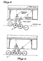
- a very large aircraft landing gear utilizing an eight wheel truck A primary two-stage shock absorber and an auxiliary single-stage shock absorber eliminating the need for torque links as seen in the landing gear of Fig. 1.
- the object of Veaux et al. is to change the lengths of the gear when the aircraft is going through its different operating conditions. This is done by external means (40, 41) relative to the 3-bar linkage comprised of 20, 24 and 8. Whereas the present invention does not use separate linkages; the 4-bar design provides inherent pitch control during all conditions of ground maneuvering, retraction and extension.
- Veaux et al. uses a two-stage approach, however in terms of kinematics, the Veaux et al. shock strut uses a sliding tube (item 14) as well which makes for a total of three telescoping components (11, 14 and 18) all three being integrated and sliding with respect to each other whereas, the present invention uses only two integrated telescoping members 8 and 9 for the main shock absorber 1 with the third member 2 being physically separate and also absorbing energy thus making for a three-stage energy absorption in terms of the preferred embodiment which is not the case for the Veaux et al. sliding tube. In terms of energy absorption, similarity with the Veaux et al.
- Veaux et al. states that a purpose of the invention is to "realize an undercarriage having one single shock absorber" (col. 1, line 47) whereas, in the present approach the purpose is not to use one but rather two separate shock absorbers to perform the same functions because there are advantages as already discussed, but only when dealing with an eight wheel truck design.
- Veaux et al. requires torque links (line 29-31, col. 4) whereas the present system does not need them (provided of course that issues raised by examining Figs 9-11 are satisfied).
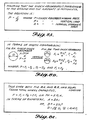
- Veaux et al. shock strut could be used in an eight wheel truck but the diametral width would be increased by approximately 40% over a two strut arrangement (all other parameters being equal). See calculations in Figs. 8A, 8B and 8C.
- Veaux et al. uses articulation of the first stage piston to provide pitch control (Fig. 3, item 24) during ground maneuvering whereas in the present system this function is performed by the separate, auxiliary shock strut 2 working in tandem with the second stage 9 of tlie main shock strut 1 (first stage 8 being fully compressed during ground maneuvers and active during take-off and landing only whereas Veaux et al. is active under all conditions).
- Grande et al. utilizes an auxiliary prop(s) 60, 62 which attaches to the main prop whereas the present system attaches to a trunnion, thus making for a different geometry.
- the Grande et al. auxiliary prop main function is to prevent tip-back whereas in the present invention a major portion of landing and ground loads is shared with the main shock absorber, or prop.
- Grande et al. requires specifically that the forward most wheels contact the ground before the rearwardmost wheels, whereas the present system indicates no preference in this regard, i.e., the aircraft can land on either the forward or the aft wheels simply by reversing the entire gear layout 180 degrees fore and aft.
- Grande et al. does not specifically assert that the system can reduce noise by minimizing aerodynamic cross-section throughout the kinematic deployment envelope while in flight.
- the unique retraction feature of the present invention is impossible to achieve using a 3-bar linkage and shock struts of roughly equal lengths and diameters. This can only be done with a 4-bar linkage.
- Veaux et al. features are used in the system of Grande et al., it is still a fundamentally different mechanism in terms of kinematic performance (retraction/extension only) compared to the present system.
- Grande et al. does not show any unique and novel benefits during the retraction/extension phase of their landing gear whereas both the present system and Veaux et al. provide such in different ways.
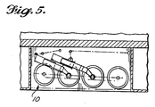
- the present eight wheel truck assembly 10 having steerable forward and aft axles comprises dual shock struts, a primary or main, two-stage shock absorber 1 and a semi-articulating secondary or auxiliary, single-stage shock absorber 2, each of which are mounted using the second 3 and third 4 axles as pivot joints in a four axle, eight wheel truck beam 5.
- the two shock struts are attached to tlie aircraft through a rotating trunnion beam 6 at their upper ends and through suitable drag and/or side strut connection(s) 7 at the lower ends of their outer cylinders.
- Rotating trunnion beam 6 is not required to be fixed as shown but may be adjusted depending on the type of aircraft installation and the desired retraction path (as mentioned herein above for the side and drag strut locations). For example a complete re-alignment of 90° to the fore and aft direction is possible for use in a wing gear installation. Then the trunnion to shock strut axes would also need similar re-alignment and possibly gimballing in tlie case of the auxiliary strut due to the nature of its motion. It should be noted that optimal side and drag strut locations are dependent on the type of aircraft installation.
- a wing gear installation could theoretically remove the trunnion member 6 and still function as intended although at the expense of other design parameters.
- the arrangement shown eliminates the need for torque links (as in Fig. 1) resulting in additional potential weight saving.
- the use of a two-stage main shock absorber 1 is vital to this invention in that it permits the desired truck beam 5 pitch attitude and "soft" damping loads at the initial contact of tires to ground during landing. This is deemed to be important as increased truck sizes may cause adverse reaction loads during the wheel spin-up phase of landing for example.
- the dual shock struts are believed to act as inherent truck pitch dampers to minimize the pitching motion of the truck beam following initial ground contact.
- the truck pitch attitude prior to landing and for proper retraction into the wheel well can be done by judicious selection of lengths and positioning of the 4-bar kinematic linkage comprised of: the truck beam 5 , auxiliary shock strut 2 , trunnion beam 6 and main shock strut 1 . Fine tuning adjustment of the truck pitch attitude can then be done by length and/or stroke alteration of the primary stage piston 8A .
- An alternative to the two-stage shock absorber feature of the present eight wheel landing gear which is less weight/cost effective consists of replacement of the main shock absorber 1 primary stage piston 8A with a sliding tube 8B and effectuating truck pitch position using hydraulics as in the system of Fig. 1.
- the two techniques of truck pitch control described above can be considered as fixed and flexible methods respectively.
- the first method using primary stage piston 8A is fixed in the sense that it cannot readily change the truck pitch attitude once each component of the mechanism is in place.
- the version utilizing sliding tube 8B being connected to a separate hydraulics control is flexible and can effectuate a range of desired truck pitch attitudes thereby permitting different truck positions for retraction into the wheel well and for landing as an example, thus allowing for optimal design for each condition.
- Fig. 9 is a schematic of a piston/cylinder assembly, typical of a shock absorber, showing a side load introduced at the lower end of the piston, point 'E'.
- the piston/cylinder Upper Bearing location is at point 'C' while the Lower Bearing location is at point 'D'.
- the cylinder attachment lugs are indicated as points 'A' and 'B', separated by distance 'd'.
- side load ⁇ S e ' is the load which can exist at either auxiliary 2 or main shock absorber 1 to truck beam 5 attachment points. This is as a result of the load conditions discussed previously above, and stems from the unique response of the 4-bar geometry of the present system, whereas in Grande et al.
Landscapes
- Engineering & Computer Science (AREA)
- Mechanical Engineering (AREA)
- Aviation & Aerospace Engineering (AREA)
- Vehicle Body Suspensions (AREA)
Abstract
Description
Claims (7)
- A landing gear for an aircraft, comprising:an eight wheel truck having four axles, all axles being substantially in line with each other and each carrying a pair of wheels with the forwardmost and rearwardmost wheels being steerable; anda two-stage main shock absorber and a single-stage auxiliary shock absorber for mounting said wheel truck to a landing gear support structure on the aircraft, said main and auxiliary shock absorbers being pivotally and separately mounted to said support structure and likewise adjacent the second and third axles respectively of said wheel truck, said combination providing truck pitch control for all conditions of aircraft handling including suitable positioning prior to landing and for retraction into the wheel well.
- The landing gear according to claim 1, wherein said main and auxiliary shock absorbers are pivotally and separately mounted on a rotating structural trunnion member such that with the inclusion of the truck, these elements comprise a 4-bar linkage such that their kinematic action permits the truck assembly to pitch up and down during aircraft ground, landing and take-off conditions.
- The landing gear of claim 2, wherein said kinematic action permits the truck assembly to remain parallel or nearly so relative to the aircraft longitudinal axis such that aerodynamic frontal area is kept to a minimum during the extension and retraction phases of landing gear deployment.
- The landing gear of claim 2, wherein said kinematic action permits the landing gear to be stowed in a reduced volume over that of two, separate, in-line with respect to each other, four-wheel trucks, each with single shock absorber, landing gears.
- The landing gear of claim 1, wherein said main and auxiliary shock absorbers act to sustain pivoting loads on the truck during aircraft ground maneuvers or aircraft yaw loads at the initial contact of either forwardmost or rearwardmost wheels during landing; pivoting loads being sustained through reactions at the upper and lower bearings of each shock absorber; and in turn, through reactions at the attachment points of each shock absorber to a structural trunnion member or to the aircraft support structure.
- A landing gear for an aircraft, comprising:an eight wheel truck having four axles, all axles being substantially in line with each other and each carrying a pair of wheels with the forwardmost and rearwardmost wheels being steerable in some manner;in combination:a single stage main shock absorber having an internal sliding tube and a single-stage auxiliary shock absorber for mounting said wheel truck to a landing gear support structure on an aircraft, said main and auxiliary shock absorbers being pivotably and separately mounted to said support structure and likewise to or near the second and third axles respectively of said wheel truck, said combination providing truck pitch control for all conditions of aircraft handling including suitable positioning prior to landing and for retraction into the wheel well;said main and auxiliary shock absorbers pivotally and separately mounted on a rotating structural trunnion member and including said eight wheel truck for providing a 4-bar linkage and kinematic action; and,said internal sliding tube being adjustable during various phases of the aircraft handling.
- A landing gear for an aircraft comprising in combination:a truck having forward and aft steerable pairs of wheels;a main shock absorber;an auxiliary shock absorber; andsaid main shock absorber and said auxiliary shock absorber act to sustain pivoting loads on said truck during aircraft ground maneuvers or aircraft yaw loads upon initial contact of either forward or aft wheels during landing of the aircraft.
Applications Claiming Priority (2)
| Application Number | Priority Date | Filing Date | Title |
|---|---|---|---|
| US821369 | 1986-01-17 | ||
| US08/821,369 US6173920B1 (en) | 1994-12-08 | 1997-03-20 | Very large aircraft landing gear having eight wheel truck |
Publications (2)
| Publication Number | Publication Date |
|---|---|
| EP0865986A2 true EP0865986A2 (en) | 1998-09-23 |
| EP0865986A3 EP0865986A3 (en) | 1999-03-31 |
Family
ID=25233204
Family Applications (1)
| Application Number | Title | Priority Date | Filing Date |
|---|---|---|---|
| EP98200851A Withdrawn EP0865986A3 (en) | 1997-03-20 | 1998-03-18 | Very large aircraft landing gear having eight wheel truck |
Country Status (2)
| Country | Link |
|---|---|
| US (1) | US6173920B1 (en) |
| EP (1) | EP0865986A3 (en) |
Cited By (2)
| Publication number | Priority date | Publication date | Assignee | Title |
|---|---|---|---|---|
| US8690432B2 (en) | 2009-04-27 | 2014-04-08 | Messier-Dowty Limited | Bearing assembly |
| US8714473B2 (en) | 2003-04-07 | 2014-05-06 | Airbus Uk Limited | Landing gear |
Families Citing this family (16)
| Publication number | Priority date | Publication date | Assignee | Title |
|---|---|---|---|---|
| US7954757B2 (en) * | 2004-03-29 | 2011-06-07 | Goodrich Corporation | Landing gear noise attenuation |
| CA2570657A1 (en) * | 2004-06-18 | 2006-07-06 | Goodrich Corporation | Landing gear with locking steering system |
| US7815143B2 (en) * | 2006-08-11 | 2010-10-19 | The Boeing Company | Aircraft landing gear truck orientation for noise reduction |
| US8820680B2 (en) * | 2008-06-30 | 2014-09-02 | Embraer S.A. | Landing gear mechanism for aircraft |
| FR2953806B1 (en) * | 2009-12-11 | 2011-12-30 | Eurocopter France | LANDING TRAIN FOR AIRCRAFT, SWING WITH PIVOT AND ARTICULATED DIABOLO |
| US8523107B2 (en) * | 2010-03-12 | 2013-09-03 | The Boeing Company | Fuselage mounted landing gear |
| GB2479223B (en) * | 2010-11-04 | 2012-11-21 | Messier Dowty Ltd | Landing gear jacking dome |
| EP2896517B1 (en) * | 2014-01-21 | 2020-01-15 | Safran Landing Systems UK Limited | Shock absorber assembly |
| EP3064432B1 (en) * | 2015-03-05 | 2017-08-09 | Safran Landing Systems UK Limited | Aircraft landing gear assembly |
| EP3135581B1 (en) * | 2015-08-25 | 2018-03-21 | Safran Landing Systems UK Limited | Aircraft landing gear assembly |
| US10766606B2 (en) * | 2017-10-17 | 2020-09-08 | Goodrich Corporation | Semi cantilevered landing gear actuated by an external articulating load damper for improved take-off |
| US11279472B2 (en) * | 2019-05-07 | 2022-03-22 | The Boeing Company | Landing gear for cargo aircraft |
| US11273908B2 (en) * | 2019-05-07 | 2022-03-15 | The Boeing Company | Folding main landing gear for cargo aircraft |
| US11319060B2 (en) * | 2019-05-07 | 2022-05-03 | The Boeing Company | Pivoting main landing gear for cargo aircraft |
| CN114162311B (en) * | 2021-10-12 | 2022-05-24 | 南京工程学院 | An electronically controlled multi-stage buffer landing gear and a method of using the same |
| CN116767513B (en) * | 2023-06-19 | 2025-07-29 | 中国飞机强度研究所 | Single-strut six-wheel landing gear supporting and loading system and method |
Citations (2)
| Publication number | Priority date | Publication date | Assignee | Title |
|---|---|---|---|---|
| US4749152A (en) | 1986-05-13 | 1988-06-07 | Messier-Hispano-Bugatti | Aircraft undercarriage of tilting-beam type and of reduced bulk |
| US5110066A (en) | 1990-04-06 | 1992-05-05 | Shimano Inc. | Speed change apparatus for a fishing reel |
Family Cites Families (18)
| Publication number | Priority date | Publication date | Assignee | Title |
|---|---|---|---|---|
| US2487548A (en) * | 1947-04-11 | 1949-11-08 | Lockheed Aircraft Corp | Main landing gear |
| US2538388A (en) * | 1949-08-02 | 1951-01-16 | Sievers George | Cross-wind landing gear for airplanes |
| GB820217A (en) | 1956-05-04 | 1959-09-16 | Electro Hydraulics Ltd | Retractable undercarriages for aircraft |
| US2851231A (en) * | 1956-08-23 | 1958-09-09 | Cleveland Pneumatic Ind Inc | Landing gear assembly |
| GB904783A (en) * | 1960-02-29 | 1962-08-29 | Dowty Rotol Ltd | Improvements relating to bogie undercarriages for aircraft |
| GB1056760A (en) * | 1963-11-18 | 1967-01-25 | Electro Hydraulics Ltd | Retractable undercarriages |
| US3904153A (en) | 1974-02-25 | 1975-09-09 | Boeing Co | Steerable and retractable aircraft nose landing gear assembly |
| GB2101542A (en) | 1981-06-13 | 1983-01-19 | British Aerospace | Aircraft undercarriage unit |
| US4770372A (en) * | 1986-09-30 | 1988-09-13 | The Boeing Company | Two-stage aircraft landing gear |
| DE69012742T2 (en) | 1989-11-09 | 1995-03-16 | Kao Corp | Azole derivatives and fungicidal drugs containing them as active components. |
| US5110068A (en) * | 1990-12-20 | 1992-05-05 | The Boeing Company | Multi-axled propped landing gear |
| FR2686857B1 (en) * | 1992-02-04 | 1994-04-01 | Messier Bugatti | AIRCRAFT LANDING LEG SHOCK ABSORBER. |
| FR2687632B1 (en) * | 1992-02-21 | 1994-04-15 | Messier Bugatti | AIRCRAFT LANDING TRAIN DESCENT. |
| FR2688190A1 (en) * | 1992-03-03 | 1993-09-10 | Messier Bugatti | REINFORCABLE LANDING TRAIN. |
| FR2689087B1 (en) | 1992-03-31 | 1994-05-13 | Messier Bugatti | LIFTABLE AERODYNES LANDER, PARTICULARLY FOR HELICOPTERS. |
| US5242131A (en) * | 1992-04-08 | 1993-09-07 | The Boeing Company | Steerable landing gear |
| US5595359A (en) | 1994-11-22 | 1997-01-21 | The Boeing Company | Landing gear axle steering |
| US5743491A (en) * | 1994-12-08 | 1998-04-28 | The Boeing Company | Very large aircraft landing gear having eight wheel truck |
-
1997
- 1997-03-20 US US08/821,369 patent/US6173920B1/en not_active Expired - Fee Related
-
1998
- 1998-03-18 EP EP98200851A patent/EP0865986A3/en not_active Withdrawn
Patent Citations (2)
| Publication number | Priority date | Publication date | Assignee | Title |
|---|---|---|---|---|
| US4749152A (en) | 1986-05-13 | 1988-06-07 | Messier-Hispano-Bugatti | Aircraft undercarriage of tilting-beam type and of reduced bulk |
| US5110066A (en) | 1990-04-06 | 1992-05-05 | Shimano Inc. | Speed change apparatus for a fishing reel |
Cited By (3)
| Publication number | Priority date | Publication date | Assignee | Title |
|---|---|---|---|---|
| US8714473B2 (en) | 2003-04-07 | 2014-05-06 | Airbus Uk Limited | Landing gear |
| US8746615B2 (en) | 2003-04-07 | 2014-06-10 | Airbus Operations Limited | Landing gear |
| US8690432B2 (en) | 2009-04-27 | 2014-04-08 | Messier-Dowty Limited | Bearing assembly |
Also Published As
| Publication number | Publication date |
|---|---|
| EP0865986A3 (en) | 1999-03-31 |
| US6173920B1 (en) | 2001-01-16 |
Similar Documents
| Publication | Publication Date | Title |
|---|---|---|
| US6173920B1 (en) | Very large aircraft landing gear having eight wheel truck | |
| US4328939A (en) | Airplane main landing gear assembly | |
| US9205917B2 (en) | Vertically retracting side articulating landing gear for aircraft | |
| US11235864B2 (en) | Landing gear | |
| US5086995A (en) | Aft cantilevered wing landing gear for heavy airplane with aft center of gravity | |
| CN100577514C (en) | Auxiliary nose landing gear, force transfer structures, and rotorcraft | |
| US8136759B2 (en) | Retractable articulated landing gear | |
| US4345727A (en) | Body-braced main airplane landing gear | |
| US9650128B2 (en) | Aircraft landing gear | |
| EP0794894B1 (en) | Very large aircraft landing gear having eight wheel truck | |
| US8844864B2 (en) | Main landing gear with rigid rear stay | |
| EP3472047B1 (en) | Aircraft landing gear | |
| US2487548A (en) | Main landing gear | |
| US11945575B2 (en) | Landing gear assembly | |
| US6349901B1 (en) | Landing gear | |
| US4940197A (en) | Aircraft undercarriage unit | |
| US5839692A (en) | Splayable aircraft nose landing gear | |
| US6811116B1 (en) | Aircraft landing gear | |
| US11273908B2 (en) | Folding main landing gear for cargo aircraft | |
| US11383827B2 (en) | Staggered wheel landing gear truck beam | |
| US20250171133A1 (en) | Aircraft landing gear with compression drag brace | |
| US20250171134A1 (en) | Aircraft landing gear with tension drag brace |
Legal Events
| Date | Code | Title | Description |
|---|---|---|---|
| PUAI | Public reference made under article 153(3) epc to a published international application that has entered the european phase |
Free format text: ORIGINAL CODE: 0009012 |
|
| AK | Designated contracting states |
Kind code of ref document: A2 Designated state(s): DE FR GB |
|
| AX | Request for extension of the european patent |
Free format text: AL;LT;LV;MK;RO;SI |
|
| PUAL | Search report despatched |
Free format text: ORIGINAL CODE: 0009013 |
|
| AK | Designated contracting states |
Kind code of ref document: A3 Designated state(s): AT BE CH DE DK ES FI FR GB GR IE IT LI LU MC NL PT SE |
|
| AX | Request for extension of the european patent |
Free format text: AL;LT;LV;MK;RO;SI |
|
| 17P | Request for examination filed |
Effective date: 19990922 |
|
| AKX | Designation fees paid |
Free format text: DE FR GB |
|
| 17Q | First examination report despatched |
Effective date: 20011120 |
|
| GRAP | Despatch of communication of intention to grant a patent |
Free format text: ORIGINAL CODE: EPIDOSNIGR1 |
|
| STAA | Information on the status of an ep patent application or granted ep patent |
Free format text: STATUS: THE APPLICATION IS DEEMED TO BE WITHDRAWN |
|
| 18D | Application deemed to be withdrawn |
Effective date: 20040702 |