EP0865541B1 - Agricultural drip tape - Google Patents
Agricultural drip tape Download PDFInfo
- Publication number
- EP0865541B1 EP0865541B1 EP96937717A EP96937717A EP0865541B1 EP 0865541 B1 EP0865541 B1 EP 0865541B1 EP 96937717 A EP96937717 A EP 96937717A EP 96937717 A EP96937717 A EP 96937717A EP 0865541 B1 EP0865541 B1 EP 0865541B1
- Authority
- EP
- European Patent Office
- Prior art keywords
- flow path
- secondary flow
- drip irrigation
- further characterised
- tape
- Prior art date
- Legal status (The legal status is an assumption and is not a legal conclusion. Google has not performed a legal analysis and makes no representation as to the accuracy of the status listed.)
- Expired - Lifetime
Links
Images


Classifications
-
- E—FIXED CONSTRUCTIONS
- E02—HYDRAULIC ENGINEERING; FOUNDATIONS; SOIL SHIFTING
- E02B—HYDRAULIC ENGINEERING
- E02B13/00—Irrigation ditches, i.e. gravity flow, open channel water distribution systems
-
- A—HUMAN NECESSITIES
- A01—AGRICULTURE; FORESTRY; ANIMAL HUSBANDRY; HUNTING; TRAPPING; FISHING
- A01G—HORTICULTURE; CULTIVATION OF VEGETABLES, FLOWERS, RICE, FRUIT, VINES, HOPS OR SEAWEED; FORESTRY; WATERING
- A01G25/00—Watering gardens, fields, sports grounds or the like
- A01G25/02—Watering arrangements located above the soil which make use of perforated pipe-lines or pipe-lines with dispensing fittings, e.g. for drip irrigation
Definitions
- This invention relates to agricultural irrigation and specifically, to a drip tape or hose construction for below or above ground drip or trickle irrigation systems.
- Drip irrigation hose or tape has been available now for several years.
- agricultural drip tapes are formed from relatively thin, flexible, continuous plastic strips folded over and seamed along a longitudinal edge to establish a primary flow path.
- One or more secondary flow paths are typically formed within the primary flow path by fixing discrete emitter devices along the length of the tape or hose, or by applying parallel strips of plastic material within the hose interior (for example, in the area of the longitudinal edge overlap to form a secondary flow path). It is generally the case that the primary flow path is connected to the water supply with inlets and outlets to and from the secondary flow path, so that water flows from the primary path to the secondary flow path, and then out of the drip tape in a controlled fashion.
- Some tape constructions employ turbulence inducing regions in the secondary flow path to prevent clogging and reduce the sensitivity of the flow rate to pressure changes.
- EP 0444425 discloses a drip irrigation line including a continuous tube which houses a plurality of flow reducer elements. Each strip comprises an inlet chamber at a first end and an outlet chamber at a second end. A flow reducer path and a connecting passageway extend between the first and second ends of the flow reducer elements. At least a portion of the material forming the connecting passageway is made of an elastomeric material.
- drip tape Despite the wealth of innovative drip irrigation technology, significant areas of concern remain relating to reliability and cost. For drip tape to be effective and commercially viable, it is essential that the secondary flow path not become clogged with solid matter in the water supply, or by outside debris blocking the outlets. At the same time, to be commercially viable, drip tape must be economical to manufacture.
- the present invention relates to a new and improved drip tape construction which offers advantages not found in the drip tape constructions of which we are presently aware.
- continuous lengths of plastic sheet or film are extruded at a predetermined thickness, while at the same time, a plastic hot melt bead is deposited along what will become the interior surface of the drip tape, in a location remote from the subsequently formed overlapped edge seam.
- the bead may be pre-formed by means of, for example, a patterned roller, so as to form a plurality of discrete secondary flow paths arranged in end-to-end relationship along the length of the hot melt bead.
- the sheet is thereafter cut, if necessary, then folded and seamed along overlapped edges to form a tubular drip tape.
- Each secondary flow path has a secondary flow channel including inlet, turbulence inducing, and outlet regions, all of which are formed by embossing or otherwise impressing a pattern of recesses and/or depressions on one side of the hot melt bead.
- the pattern side of the bead is applied face down on the sheet so that the sheet wall itself closes the secondary flow channel except for a plurality of inlets formed in the bead at longitudinally spaced locations along the inlet region. These inlets are arranged perpendicular to the longitudinal axis of the tape, and thus also perpendicular to the secondary flow channel.
- the inlets are located on both sides of the secondary flow channel, in longitudinally spaced relationship, with the inlets on one side of the secondary flow channel offset longitudinally with respect to the inlets on the opposite side of the secondary flow channel.
- the inlet region extends well over half the total length of the secondary flow path, but this dimensional relationship may vary.
- the inlet region leads to a turbulence inducing region formed by a series of peaks and valleys on opposite sides of the secondary flow channel, in longitudinally offset relationship so that the peaks on one side of the secondary flow channel in this region project towards the valleys on the opposite side of the flow channel.
- the peaks projecting from both sides of the secondary flow channel lie along a line through the center of the secondary flow channel in the exemplary embodiment, thus creating a tortuous path which induces turbulence in the secondary flow path. It is this turbulence that dissipates energy and creates zero or near zero pressure discharge to atmosphere.
- the turbulence also prevents clogging of the secondary flow path by debris or other solid impurities within the primary water supply.
- an outlet region Downstream of the turbulence inducing region, an outlet region is provided which communicates with an elongated slit in the tape wall which allows the water in the secondary flow path to escape in a controlled drip-like fashion.
- the outlet region, or reservoir is otherwise axially closed in the downstream direction, thus isolating the path from the inlet region of the next adjacent downstream secondary flow path, and thus also forcing all water to exit via the elongated slit in the tape wall.
- the secondary flow path is formed of substantially transparent or at least translucent material which allows the user to inspect the tape for clogging. This inspection can occur simply by removing an axial section of the drip tape and cutting it longitudinally so that the user may then fold the tape open to inspect the secondary flow path.
- Another feature of the invention resides in the geometry of the secondary flow path in general and the turbulence inducing region in particular, as described in greater detail further hereinbelow.
- the invention in its broader aspects, relates to agricultural drip irrigation tape comprising a tubular member defining a primary flow path; a substantially transparent strip member secured to a surface of the tubular member and defining at least one secondary flow path; at least one inlet from the primary flow path to the secondary flow path; and at least one outlet from the secondary flow path to atmosphere.
- the present invention relates to drip tape for below (and/or above) ground irrigation comprising an elongated flexible tubular member forming a primary flow path; an elongated substantially transparent strip secured to an interior surface of the tubular member, the strip formed to include at least one secondary flow path; a plurality of inlets in the strip connecting the primary flow path to the secondary flow path; and an outlet in the tubular member connecting the secondary flow path to atmosphere.
- the invention in another aspect, relates to agricultural drip tape comprising a tubular member defining a primary flow path; a strip member secured to a surface of the tubular member and defining, with the tubular member, a secondary flow path having a flow channel therein; the secondary flow path including axially aligned inlet, turbulence inducing and outlet regions, wherein the inlet region comprises a plurality of inlet openings formed in opposite sides of the strip, perpendicular to the flow channel, with inlets on one side longitudinally offset from inlets on the other side; and at least one outlet from the secondary flow path to atmosphere.
- the invention relates to drip tape for below ground (and/or above ground) irrigation comprising a sheet of material formed into a tube by overlapping opposite side edges of the strip and bonding the side edges along a longitudinal seam thereby forming a primary flow path; a strip of material bonded to an interior surface of the tube at a location remote from the longitudinal seam; the strip of material and the sheet of material defining a plurality of secondary flow paths within the primary flow path having a radially inner wall defined in part by a reduced thickness portion of the strip and a radially outer wall defined by the tube, each secondary flow path including an inlet region, a turbulence inducing region and an outlet region; the inlet region including a plurality of inlets on opposite sides of the second strip connecting the primary flow path to the secondary flow path upstream of the turbulence inducing region; the outlet region including an outlet in the tube connecting the secondary flow path to atmosphere downstream of the turbulence inducing region.
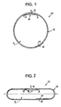
- a drip tape configuration in accordance with the invention is shown generally at 10 and includes a flexible plastic sheet or film 12 with opposite longitudinal edges 14 and 16 overlapped and bonded (by, for example, adhesive or by heat sealing) to form a tubular tape or hose with a single longitudinal seam.
- a longitudinally oriented strip of plastic material 18 is applied to the inner surface of the tape at a location remote from the overlapped seam.
- the tape itself forms a primary flow path P 1 while the strip 18 is preformed to define a plurality of axially aligned secondary flow paths P 2 (see Figures 3), described further below.
- the secondary flow paths extend along and parallel to the longitudinal axis of the tape.
- the strip 18 in the preferred embodiment may be provided in the form of an extruded hot melt plastic bead having a width of about 0.25", deposited (and bonded) on the "inside" surface of the sheet 12, prior to seaming the overlapped ends 14 and 16.
- the bead may be preformed prior to deposit on sheet 12, by, for example, extruding the bead onto a roller which subsequently meshes with a second patterned roller to form the individual secondary flow paths along the bead. Thereafter, the bead is deposited onto the sheet surface where it is bonded via the heat of the bead. Tooling may be arranged so that the pre-formed bead is deposited on the sheet as the latter exits its own extrusion die. Of course, other plastic forming methods may be employed as well.
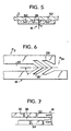
- the pattern which is embossed or pressed into one side of the strip 18 is best seen in Figure 3.
- the pattern defines a plurality of secondary flow paths P 2 , P 2a , P 2b , etc., in discrete longitudinal segments, e.g., about every 12" along the length of the bead or strip. It will be appreciated, however, that the secondary flow paths may be spaced at other intervals, e.g., 4", 8", 12", 24", 36", etc.
- Each secondary flow path (one shown in Figure 3) has three distinct regions - an inlet region 20, a turbulence inducing region 22 and an outlet region 24, all within a secondary flow channel 26 running longitudinally or axially through the regions, with a depth of about 0.015".
- the inlet region 20 of secondary flow path P 2 begins at a chevron-shaped end 28, adjacent an isolated chevron 28', thus providing a clear line of demarcation between flow path P 2 and the outlet region 30 of the immediately preceding flow path P 2a .
- the inlet region extends for well over half of the length dimension of the flow path (i.e., about 9" in the exemplary embodiment, but this dimensional relationship may vary) and includes a plurality of laterally disposed, longitudinally spaced inlets 32 on one side of the strip 18 and a similar number of like inlets 34 on the other side of the strip 18.
- the inlets 32 on one side of the bead are longitudinally offset from the inlets 32 on the opposite side of the bead thus insuring continuous bead contact with the tape wall.
- the inlets 32, 34 extend perpendicularly to the secondary flow channel 26 and hence also to the longitudinal axis of the tape.
- Each inlet has a width dimension of about 0.018", and the inlets on either side are spaced apart by about 0.25".
- the turbulence inducing region 22 which is best seen in Figure 8.
- This region which extends a distance of about 1.9" in the exemplary embodiment has no inlets or outlets other than at the front and back thereof as defined by the flow channel 26, and describes a tortuous path designed to cause turbulent flow which prevents clogging and which dissipates flow energy to create a zero or near zero discharge of water to atmosphere through the outlets described below.
- the path is formed by a series of asymmetrically arranged arcs, laterally opposed but longitudinally offset from one another, such that pointed peaks 36 project from one side of the channel 26 into valleys 38 between similarly pointed peaks 40 on the other side of the flow channel.
- each "valley” is composed of at least two different radii drawn from different centers (laterally offset from the channel centerline and slightly axially offset as well).
- R 1 for example, may be 0.0400" and R 2 may be 0.0306".
- Each valley has a maximum depth of about 0.0281 inch as measured approximately from the centerline of the flow channel.
- all of the peaks 36 and 40 lie on a horizontal line extending through the center of the secondary flow channel 26.
- the peak-to-peak dimension on each side of the secondary flow channel is about 0.077" while the peak-to-peak dimension of adjacent peaks (alternating sides) is about 0.038".
- the width dimension of the turbulence inducing region 22 nowhere exceeds the width of the inlet region 20. It is also noted that the relatively larger radius R 1 essentially creates a straight line at about a 40° angle to the longitudinal axis of the tape.
- the specific dimensions and geometrical relationship may vary.
- grooves G 1 , G 2 which extend the full length of the region 22, on opposite sides of the flow channel 26. These grooves G 1 , G 2 , along with chevron 28' and the general arrangement of inlets 32, 34 (on opposite sides of the channel 26) are employed to insure uniform distribution of material during the pre-forming of the hot melt bead, and to improve the definition of the geometry in the turbulent region. In other words, the grooves insure complete “filling" of the geometry in the turbulent region and make the path integrity much less sensitive to slight variations in the output of the extruder that applies the hot melt bead 18. Uniformity is particularly important in that bulges or other surface discontinuities are prevented which might otherwise negatively impact on the integrity of the seal between the strip 18 and the tape 12, particularly as it relates to the flow channel 26 and the isolation of the secondary flow paths from each other.
- outlet region or reservoir 24 Downstream of the turbulence inducing region 22 is the outlet region or reservoir 24 which is formed by smooth channel side walls 42, 44 and which terminates at a closed, pointed end 46 adjacent the chevron 28 of the next adjacent flow path P 2b .
- the outlet portion or region of flow path 26 has a greater width dimension than the inlet region 20 (e.g., 0.0800" as compared to 0.0566"), and a length of about 1".
- the slit 48 has a length dimension of about 0.45".
- Figures 3, 4, 6, 7 and 8 show the strip 18 in plan, with the open pattern facing upwardly. It is this face of the strip 18 which is bonded to the interior surface of the sheet 12, so that the secondary flow path 26 is closed along the radially outermost face of the tape. Accordingly, water can enter the secondary flow channel 26 of each path P 2 only through inlets 32, 34 and can exit only via the slit 48.
- the thickness of the sheet 12 is essentially equal to the bead thickness T in the flow channel 26.
- the radially inner and outer walls of the flow path 26 are of substantially the same thickness, e.g., 0.010 inch, such that water pressure changes have little or no impact on the cross sectional sizes of the primary and secondary flow paths.
- the sheet 18 is preferably transparent (or at least translucent) so that the user can inspect the tape for clogging This inspection is accomplished by simply removing an axial section of the tape of a few inches or more in length and then cutting the removed section longitudinally so that the strip 18 is clearly visible. Later, a plain length of tape, or similar drip tape section, can be spliced into place.
- the sheet 12 is formed of a blend of commercially available polyethylenes. It should be understood that all dimensions and materials recited herein are exemplary only, and may be varied depending on circumstances and objectives. For example, it is well within the skill of the art to engineer material blends (with or without additives) which will meet requirements for specific end use applications.
Landscapes
- Engineering & Computer Science (AREA)
- General Engineering & Computer Science (AREA)
- Life Sciences & Earth Sciences (AREA)
- Structural Engineering (AREA)
- Environmental Sciences (AREA)
- Water Supply & Treatment (AREA)
- Mechanical Engineering (AREA)
- Civil Engineering (AREA)
- Soil Sciences (AREA)
- Extrusion Moulding Of Plastics Or The Like (AREA)
- Catching Or Destruction (AREA)
- Agricultural Chemicals And Associated Chemicals (AREA)
- Greenhouses (AREA)
- Organic Insulating Materials (AREA)
- Adhesive Tapes (AREA)
- Protection Of Plants (AREA)
Abstract
Description
Claims (12)
- Agriculture drip irrigation tape (10) having a tubular member defining a primary flow path (P1); a strip member (18) secured to an interior surface of said tubular member and defining at least one secondary flow path (P2); at least one inlet (20) from said primary flow path to said secondary flow path (P2); and at least one outlet (24) from said secondary flow path to atmosphere, characterised in that said strip member (18) is substantially transparent.
- The agricultural drip irrigation tape of claim 1 further characterised in that a plurality of said secondary flow paths (P2, P2a, P2b) are formed in said substantially transparent strip member (18), in longitudinally spaced, axially aligned relationship.
- The agricultural dip irrigation tape of claim 2 further characterised in that each secondary flow path is formed with discrete axially aligned inlet (20), turbulence inducing regions (22), and outlet regions (24), with a secondary flow channel (26) extending through said regions.
- The agricultural drip irrigation tape of claim 3 further characterised in that a plurality of inlets (32, 34) are formed in opposite side walls of the strip (18) in longitudinally offset relationship.
- The agricultural drip irrigation tape of claim 4 further characterised in that said inlets (32, 34) extend perpendicular to said secondary flow path.
- The agricultural drip irrigation tape of claim 1 further characterised in that said outlet (24) comprises a single elongated slit (48).
- The agricultural drip irrigation tape of claim 3 further characterised in that said inlet region (20) extends for at least half the length dimension of said secondary flow path.
- The agricultural drip irrigation tape of claim 3 further characterised in that said turbulence inducing region (22) comprises a series of peaks (36, 40) and valleys (38) formed in opposite side walls of said secondary flow path, with peaks (36, 40) on one side projecting towards valleys (38) on the other side.
- The agricultural drip irrigation tape of claim 8 further characterised in that said peaks (36, 40) on opposite side walls lie along a longitudinal axis of the tape.
- The agricultural drip irrigation tape of claim 8 further characterised in that each valley (38) is formed by different radii having different diameters.
- The agricultural drip irrigation tape of any preceding claim further characterised in that said tubular member is formed by overlapping opposite side edges (14, 16) of a sheet strip and bonding said side edges along a longitudinal seam.
- The agricultural drip irrigation tape of claim 1 further characterised in that said strip member (18) is provided with means for enhancing uniform distribution of material during formation of the secondary flow path.
Applications Claiming Priority (3)
| Application Number | Priority Date | Filing Date | Title |
|---|---|---|---|
| US08/570,014 US5688072A (en) | 1995-12-14 | 1995-12-14 | Agricultural drip tape |
| US570014 | 1995-12-14 | ||
| PCT/US1996/016970 WO1997021874A1 (en) | 1995-12-14 | 1996-10-31 | Agricultural drip tape |
Publications (3)
| Publication Number | Publication Date |
|---|---|
| EP0865541A1 EP0865541A1 (en) | 1998-09-23 |
| EP0865541A4 EP0865541A4 (en) | 2000-02-23 |
| EP0865541B1 true EP0865541B1 (en) | 2003-07-09 |
Family
ID=24277835
Family Applications (1)
| Application Number | Title | Priority Date | Filing Date |
|---|---|---|---|
| EP96937717A Expired - Lifetime EP0865541B1 (en) | 1995-12-14 | 1996-10-31 | Agricultural drip tape |
Country Status (8)
| Country | Link |
|---|---|
| US (1) | US5688072A (en) |
| EP (1) | EP0865541B1 (en) |
| AT (1) | ATE244796T1 (en) |
| AU (1) | AU706488B2 (en) |
| DE (1) | DE69629048D1 (en) |
| ES (1) | ES2203720T3 (en) |
| IL (1) | IL124833A (en) |
| WO (1) | WO1997021874A1 (en) |
Families Citing this family (21)
| Publication number | Priority date | Publication date | Assignee | Title |
|---|---|---|---|---|
| US6120634A (en) | 1997-02-26 | 2000-09-19 | Micro Irrigation Technologies, Inc. | Method and apparatus for forming agricultural drip tape |
| WO2001031999A1 (en) * | 1999-10-29 | 2001-05-10 | Rodney Ruskin | Improving the long-term diffusion rate of controlled release herbicides in thin-walled drip irrigation lines |
| US6620278B1 (en) * | 2000-04-18 | 2003-09-16 | Nelson Irrigation Corporation | Drip tape manufacturing process |
| US6382530B1 (en) * | 2000-07-10 | 2002-05-07 | Nelson Irrigation Corporation | Pressure compensating drip tape |
| US6736337B2 (en) | 2002-02-08 | 2004-05-18 | The Toro Company | Pressure compensating drip irrigation hose |
| US20050258279A1 (en) * | 2004-05-24 | 2005-11-24 | Nelson Irrigation Corporation | Pressure compensating drip tape and related method |
| US20050284966A1 (en) * | 2004-06-23 | 2005-12-29 | Defrank Michael | Emitter |
| US7108205B1 (en) * | 2005-03-01 | 2006-09-19 | D.R.T.S. Enterprises Ltd. | Drip irrigation system employing parallel adjacent flowpaths |
| ITSV20050042A1 (en) | 2005-12-15 | 2007-06-16 | Siplast S P A | IRRIGATOR TUBE |
| KR100754779B1 (en) * | 2007-02-21 | 2007-09-03 | 주식회사 서원양행 | Pressure control drip tape and hose |
| US20090224078A1 (en) * | 2008-03-04 | 2009-09-10 | Anderson Noel W | Biodegradable irrigation drip tape and method of using same |
| US20100327084A1 (en) * | 2009-06-25 | 2010-12-30 | Boice Jr Nelson | Drip Irrigation Hose |
| MX349566B (en) * | 2011-01-04 | 2017-08-03 | Jain Irrigation Systems Ltd | Apparatus nd method of manufacturing pressure compensator type drip irrigation tubes with desired molecular orientation and tubes obtained thereby. |
| MX2016015852A (en) * | 2014-06-03 | 2017-05-23 | Jain Irrigation Systems Ltd | A fluid conveying apparatus. |
| US10375904B2 (en) | 2016-07-18 | 2019-08-13 | Rain Bird Corporation | Emitter locating system and related methods |
| USD883048S1 (en) | 2017-12-12 | 2020-05-05 | Rain Bird Corporation | Emitter part |
| US11985924B2 (en) | 2018-06-11 | 2024-05-21 | Rain Bird Corporation | Emitter outlet, emitter, drip line and methods relating to same |
| US11497178B2 (en) | 2019-06-14 | 2022-11-15 | The Toro Company | Drip irrigation emitter with optimized clog resistance |
| DE102019213351A1 (en) | 2019-09-03 | 2021-03-04 | Fraunhofer-Gesellschaft zur Förderung der angewandten Forschung e.V. | Process for the production of fiber-reinforced composite materials with stabilized fibers, fiber coatings and / or fiber bundle coatings |
| US20220347961A1 (en) * | 2021-04-29 | 2022-11-03 | Cmd Corporation | Web processing machines with ultrasonic sealers |
| US20220399796A1 (en) * | 2021-06-14 | 2022-12-15 | International Business Machines Corporation | Device for actuating a physical object by magnetically driven fluid flow |
Family Cites Families (39)
| Publication number | Priority date | Publication date | Assignee | Title |
|---|---|---|---|---|
| US2059927A (en) * | 1935-07-10 | 1936-11-03 | Oscar G Beck | Water passover |
| US3361359A (en) * | 1966-01-10 | 1968-01-02 | Richard D. Chapin | Soil soaking system |
| US3903929A (en) * | 1971-11-10 | 1975-09-09 | Anjac Plastics | Irrigation conduit |
| US3736755A (en) * | 1972-02-23 | 1973-06-05 | R Hammond | Irrigation system |
| US3870236A (en) * | 1973-03-14 | 1975-03-11 | Sahagun Barragan Jaime | Dripping irrigation tubing |
| US3896999A (en) * | 1973-09-28 | 1975-07-29 | Jaime Sahagun Barragan | Anti-clogging drip irrigation valve |
| ZA754678B (en) * | 1974-08-06 | 1976-06-30 | U Tiedt | Control system for the uniform distribution of fluid in a hose or tube |
| MX143576A (en) * | 1977-04-11 | 1981-06-03 | Jaime Sahagun Barragan | IMPROVEMENTS IN INTEGRAL DRIP IRRIGATION SYSTEM |
| US4126998A (en) * | 1977-10-14 | 1978-11-28 | Gideon Gilead | Irrigation apparatus |
| IL67824A (en) * | 1977-11-24 | 1985-08-30 | Hydro Plan Eng Ltd | Irrigation drip emitter unit |
| DE2924708A1 (en) * | 1979-06-19 | 1981-01-22 | Gideon Gilead | METHOD FOR PRODUCING AN IRRIGATION HOSE AND METHOD OF A IRRIGATION HOSE PRODUCED BY THIS METHOD |
| US4247051A (en) * | 1979-12-20 | 1981-01-27 | Davies Allport | Irrigation hose and method for its construction |
| IL60071A (en) * | 1980-05-14 | 1990-02-09 | Gilead Gideon | Apparatus for drip irrigation |
| IL63341A (en) * | 1981-07-15 | 1996-09-12 | Naan Mech Works | Drip irrigation apparatus |
| US4437431A (en) * | 1981-11-06 | 1984-03-20 | Koch David L | Method and apparatus for diversion of downstream migrating anadromous fish |
| US4534515A (en) * | 1982-04-01 | 1985-08-13 | Chapin Richard D | Drip irrigation system employing adjacently arranged flow-restricting passages |
| US4642152A (en) * | 1982-04-01 | 1987-02-10 | Chapin Richard D | Drip irrigation system employing flow regulation |
| US4473191A (en) * | 1982-04-01 | 1984-09-25 | Chapin Richard D | Drip irrigation system employing flow regulation |
| US4572756A (en) * | 1982-04-01 | 1986-02-25 | Chapin Richard D | Drip irrigation system employing adjacently arranged flow-restricting passages |
| US4430020A (en) * | 1982-09-29 | 1984-02-07 | Robbins Jackie W D | Drip irrigation hose |
| US4629361A (en) * | 1983-12-07 | 1986-12-16 | Zimmerman Richard J | Integrated tubal by-pass fishway |
| US4626130A (en) * | 1983-12-12 | 1986-12-02 | Chapin Richard D | Drip irrigation system |
| IT1196295B (en) * | 1984-10-15 | 1988-11-16 | Enichem Polimeri | DROP WING FOR LOCALIZED IRRIGATION |
| US4984739A (en) * | 1986-08-04 | 1991-01-15 | Davies Allport | Drip irrigation hose |
| US4817875A (en) * | 1987-09-21 | 1989-04-04 | David Karmeli | Flexible pipe for trickle irrigation |
| US4880167A (en) * | 1987-09-23 | 1989-11-14 | James Hardie Irrigation, Inc. | Irrigation hose with linear turbulent flow emitter |
| US5318657A (en) * | 1988-02-16 | 1994-06-07 | Roberts James C | Drip irrigation tape and method of manufacture |
| US5181532A (en) * | 1988-09-16 | 1993-01-26 | Lage Brodefors | Flow control |
| IL91571A (en) * | 1989-09-08 | 1995-03-30 | Agroteam Consultants Ltd | Drip irrigation line and method of making same |
| US5263791A (en) * | 1989-09-18 | 1993-11-23 | David Zeman | Irrigation tubing with improved discharge holes |
| IL93255A (en) * | 1990-02-02 | 1997-03-18 | Plastro Gvat | Drip irrigation lines |
| US5117580A (en) * | 1990-07-02 | 1992-06-02 | Brown G Marvin | Heat transfer tube for a seedbed cover |
| US5183208A (en) * | 1990-07-20 | 1993-02-02 | Agroteam Consultants Ltd. | Drip irrigation emitter |
| US5123984A (en) * | 1990-08-17 | 1992-06-23 | T-Systems International, Inc. | Method and apparatus for forming ports in drip irrigation hose |
| US5118042A (en) * | 1991-02-22 | 1992-06-02 | William A. Delmer | Multiple chamber drip irrigation hose |
| US5207386A (en) * | 1991-10-01 | 1993-05-04 | Hydro-Plan Engineering Ltd. | Flow emitter units moulds for use in the manufacture thereof |
| US5192027A (en) * | 1992-02-11 | 1993-03-09 | Delmer Daniel W C | Drip irrigation devices and plastic films with copper powder incorporated |
| US5282578A (en) * | 1993-02-08 | 1994-02-01 | T-Systems International, Inc. | Self-protecting irrigation hose and method |
| US5333793A (en) * | 1993-07-21 | 1994-08-02 | T-Systems International, Inc. | Drip irrigation hose with pressure compensation and method for its manufacture |
-
1995
- 1995-12-14 US US08/570,014 patent/US5688072A/en not_active Expired - Fee Related
-
1996
- 1996-10-31 IL IL12483396A patent/IL124833A/en not_active IP Right Cessation
- 1996-10-31 EP EP96937717A patent/EP0865541B1/en not_active Expired - Lifetime
- 1996-10-31 AU AU75191/96A patent/AU706488B2/en not_active Ceased
- 1996-10-31 ES ES96937717T patent/ES2203720T3/en not_active Expired - Lifetime
- 1996-10-31 DE DE69629048T patent/DE69629048D1/en not_active Expired - Lifetime
- 1996-10-31 WO PCT/US1996/016970 patent/WO1997021874A1/en active IP Right Grant
- 1996-10-31 AT AT96937717T patent/ATE244796T1/en not_active IP Right Cessation
Also Published As
| Publication number | Publication date |
|---|---|
| ES2203720T3 (en) | 2004-04-16 |
| IL124833A (en) | 2000-12-06 |
| AU706488B2 (en) | 1999-06-17 |
| US5688072A (en) | 1997-11-18 |
| WO1997021874A1 (en) | 1997-06-19 |
| DE69629048D1 (en) | 2003-08-14 |
| EP0865541A1 (en) | 1998-09-23 |
| AU7519196A (en) | 1997-07-03 |
| IL124833A0 (en) | 1999-01-26 |
| EP0865541A4 (en) | 2000-02-23 |
| ATE244796T1 (en) | 2003-07-15 |
Similar Documents
| Publication | Publication Date | Title |
|---|---|---|
| EP0865541B1 (en) | Agricultural drip tape | |
| EP0809933B1 (en) | Drip irrigation hose | |
| US5865377A (en) | Drip irrigation hose and method for its manufacture | |
| US5522551A (en) | Drip irrigation hose and method for its manufacture | |
| US6371390B1 (en) | Drip irrigation hose and method of making same | |
| EP0702600B1 (en) | Drip irrigation hose and method of manufacture | |
| EP0709020B1 (en) | Constant-flow irrigation tape and method of making | |
| US5855324A (en) | Drip irrigation hose and method of its manufacture | |
| US5732887A (en) | Drip irrigation tape and method of manufacture | |
| US20050258279A1 (en) | Pressure compensating drip tape and related method | |
| US5673852A (en) | Drip irrigation tape and method of manufacture | |
| EP0293857B1 (en) | Irrigation device | |
| US4548360A (en) | Multichamber drip irrigation hose | |
| AU1701700A (en) | Spiral wound pipe and a method for manufacturing the same | |
| JPS616484A (en) | Continuous pipe discharger and manufacture thereof | |
| US5634595A (en) | Drip irrigation hose and method for its manufacture | |
| AU723101B2 (en) | Drip irrigation hose and method of its manufacture | |
| JPH05505515A (en) | Drop irrigation pipe and its manufacturing method | |
| FI68751B (en) | DOUBLE FLOATING SHEET FOR FITTING AND FITTING | |
| WO1998038847A2 (en) | Drip irrigation hose with self-cleaning inlet | |
| CA2239153C (en) | Drip irrigation hose and method of its manufacture | |
| IL120946A (en) | Drip irrigation hose and method of its manufacture | |
| IL117428A (en) | Apparatus and method for manufacturing drip irrigation hose | |
| MXPA06013592A (en) | Drip irrigation hose and method for making same. |
Legal Events
| Date | Code | Title | Description |
|---|---|---|---|
| PUAI | Public reference made under article 153(3) epc to a published international application that has entered the european phase |
Free format text: ORIGINAL CODE: 0009012 |
|
| 17P | Request for examination filed |
Effective date: 19980615 |
|
| AK | Designated contracting states |
Kind code of ref document: A1 Designated state(s): AT DE DK ES FR GB GR IT PT |
|
| A4 | Supplementary search report drawn up and despatched |
Effective date: 20000112 |
|
| AK | Designated contracting states |
Kind code of ref document: A4 Designated state(s): AT DE DK ES FR GB GR IT PT |
|
| RIC1 | Information provided on ipc code assigned before grant |
Free format text: 7E 02B 13/00 A, 7A 01G 25/02 B |
|
| RAP1 | Party data changed (applicant data changed or rights of an application transferred) |
Owner name: MICRO IRRIGATION TECHNOLOGIES, INC. |
|
| 17Q | First examination report despatched |
Effective date: 20020409 |
|
| GRAH | Despatch of communication of intention to grant a patent |
Free format text: ORIGINAL CODE: EPIDOS IGRA |
|
| GRAH | Despatch of communication of intention to grant a patent |
Free format text: ORIGINAL CODE: EPIDOS IGRA |
|
| GRAA | (expected) grant |
Free format text: ORIGINAL CODE: 0009210 |
|
| AK | Designated contracting states |
Designated state(s): AT DE DK ES FR GB GR IT PT |
|
| PG25 | Lapsed in a contracting state [announced via postgrant information from national office to epo] |
Ref country code: AT Free format text: LAPSE BECAUSE OF FAILURE TO SUBMIT A TRANSLATION OF THE DESCRIPTION OR TO PAY THE FEE WITHIN THE PRESCRIBED TIME-LIMIT Effective date: 20030709 |
|
| REG | Reference to a national code |
Ref country code: GB Ref legal event code: FG4D |
|
| REF | Corresponds to: |
Ref document number: 69629048 Country of ref document: DE Date of ref document: 20030814 Kind code of ref document: P |
|
| PG25 | Lapsed in a contracting state [announced via postgrant information from national office to epo] |
Ref country code: GR Free format text: LAPSE BECAUSE OF FAILURE TO SUBMIT A TRANSLATION OF THE DESCRIPTION OR TO PAY THE FEE WITHIN THE PRESCRIBED TIME-LIMIT Effective date: 20031009 Ref country code: DK Free format text: LAPSE BECAUSE OF FAILURE TO SUBMIT A TRANSLATION OF THE DESCRIPTION OR TO PAY THE FEE WITHIN THE PRESCRIBED TIME-LIMIT Effective date: 20031009 |
|
| PG25 | Lapsed in a contracting state [announced via postgrant information from national office to epo] |
Ref country code: DE Free format text: LAPSE BECAUSE OF FAILURE TO SUBMIT A TRANSLATION OF THE DESCRIPTION OR TO PAY THE FEE WITHIN THE PRESCRIBED TIME-LIMIT Effective date: 20031010 |
|
| PG25 | Lapsed in a contracting state [announced via postgrant information from national office to epo] |
Ref country code: GB Free format text: LAPSE BECAUSE OF NON-PAYMENT OF DUE FEES Effective date: 20031031 |
|
| PG25 | Lapsed in a contracting state [announced via postgrant information from national office to epo] |
Ref country code: PT Free format text: LAPSE BECAUSE OF FAILURE TO SUBMIT A TRANSLATION OF THE DESCRIPTION OR TO PAY THE FEE WITHIN THE PRESCRIBED TIME-LIMIT Effective date: 20031209 |
|
| REG | Reference to a national code |
Ref country code: ES Ref legal event code: FG2A Ref document number: 2203720 Country of ref document: ES Kind code of ref document: T3 |
|
| ET | Fr: translation filed | ||
| PLBE | No opposition filed within time limit |
Free format text: ORIGINAL CODE: 0009261 |
|
| STAA | Information on the status of an ep patent application or granted ep patent |
Free format text: STATUS: NO OPPOSITION FILED WITHIN TIME LIMIT |
|
| GBPC | Gb: european patent ceased through non-payment of renewal fee |
Effective date: 20031031 |
|
| 26N | No opposition filed |
Effective date: 20040414 |
|
| PGFP | Annual fee paid to national office [announced via postgrant information from national office to epo] |
Ref country code: FR Payment date: 20041004 Year of fee payment: 9 |
|
| PGFP | Annual fee paid to national office [announced via postgrant information from national office to epo] |
Ref country code: ES Payment date: 20041022 Year of fee payment: 9 |
|
| PG25 | Lapsed in a contracting state [announced via postgrant information from national office to epo] |
Ref country code: IT Free format text: LAPSE BECAUSE OF NON-PAYMENT OF DUE FEES Effective date: 20051031 |
|
| PG25 | Lapsed in a contracting state [announced via postgrant information from national office to epo] |
Ref country code: ES Free format text: LAPSE BECAUSE OF NON-PAYMENT OF DUE FEES Effective date: 20051102 |
|
| PG25 | Lapsed in a contracting state [announced via postgrant information from national office to epo] |
Ref country code: FR Free format text: LAPSE BECAUSE OF NON-PAYMENT OF DUE FEES Effective date: 20060630 |
|
| REG | Reference to a national code |
Ref country code: FR Ref legal event code: ST Effective date: 20060630 |
|
| REG | Reference to a national code |
Ref country code: ES Ref legal event code: FD2A Effective date: 20051102 |