EP0864743A2 - Fuel injection valve for internal combustion engines - Google Patents
Fuel injection valve for internal combustion engines Download PDFInfo
- Publication number
- EP0864743A2 EP0864743A2 EP97120314A EP97120314A EP0864743A2 EP 0864743 A2 EP0864743 A2 EP 0864743A2 EP 97120314 A EP97120314 A EP 97120314A EP 97120314 A EP97120314 A EP 97120314A EP 0864743 A2 EP0864743 A2 EP 0864743A2
- Authority
- EP
- European Patent Office
- Prior art keywords
- valve
- piston
- fuel injection
- hydraulic
- valve member
- Prior art date
- Legal status (The legal status is an assumption and is not a legal conclusion. Google has not performed a legal analysis and makes no representation as to the accuracy of the status listed.)
- Granted
Links
- 238000002347 injection Methods 0.000 title claims abstract description 50
- 239000007924 injection Substances 0.000 title claims abstract description 50
- 239000000446 fuel Substances 0.000 title claims abstract description 36
- 238000002485 combustion reaction Methods 0.000 title claims abstract description 22
- 238000007789 sealing Methods 0.000 claims abstract description 10
- 238000013016 damping Methods 0.000 description 2
- 238000000034 method Methods 0.000 description 2
- 238000000926 separation method Methods 0.000 description 2
- 230000003321 amplification Effects 0.000 description 1
- 230000005540 biological transmission Effects 0.000 description 1
- 230000003111 delayed effect Effects 0.000 description 1
- 230000001419 dependent effect Effects 0.000 description 1
- 238000006073 displacement reaction Methods 0.000 description 1
- 230000000694 effects Effects 0.000 description 1
- 238000003199 nucleic acid amplification method Methods 0.000 description 1
- 230000002123 temporal effect Effects 0.000 description 1
- 230000001960 triggered effect Effects 0.000 description 1
Images

Classifications
-
- F—MECHANICAL ENGINEERING; LIGHTING; HEATING; WEAPONS; BLASTING
- F02—COMBUSTION ENGINES; HOT-GAS OR COMBUSTION-PRODUCT ENGINE PLANTS
- F02M—SUPPLYING COMBUSTION ENGINES IN GENERAL WITH COMBUSTIBLE MIXTURES OR CONSTITUENTS THEREOF
- F02M51/00—Fuel-injection apparatus characterised by being operated electrically
- F02M51/06—Injectors peculiar thereto with means directly operating the valve needle
- F02M51/0603—Injectors peculiar thereto with means directly operating the valve needle using piezoelectric or magnetostrictive operating means
-
- F—MECHANICAL ENGINEERING; LIGHTING; HEATING; WEAPONS; BLASTING
- F02—COMBUSTION ENGINES; HOT-GAS OR COMBUSTION-PRODUCT ENGINE PLANTS
- F02M—SUPPLYING COMBUSTION ENGINES IN GENERAL WITH COMBUSTIBLE MIXTURES OR CONSTITUENTS THEREOF
- F02M47/00—Fuel-injection apparatus operated cyclically with fuel-injection valves actuated by fluid pressure
- F02M47/04—Fuel-injection apparatus operated cyclically with fuel-injection valves actuated by fluid pressure using fluid, other than fuel, for injection-valve actuation
- F02M47/046—Fluid pressure acting on injection-valve in the period of injection to open it
-
- F—MECHANICAL ENGINEERING; LIGHTING; HEATING; WEAPONS; BLASTING
- F02—COMBUSTION ENGINES; HOT-GAS OR COMBUSTION-PRODUCT ENGINE PLANTS
- F02M—SUPPLYING COMBUSTION ENGINES IN GENERAL WITH COMBUSTIBLE MIXTURES OR CONSTITUENTS THEREOF
- F02M2200/00—Details of fuel-injection apparatus, not otherwise provided for
- F02M2200/70—Linkage between actuator and actuated element, e.g. between piezoelectric actuator and needle valve or pump plunger
- F02M2200/703—Linkage between actuator and actuated element, e.g. between piezoelectric actuator and needle valve or pump plunger hydraulic
- F02M2200/704—Linkage between actuator and actuated element, e.g. between piezoelectric actuator and needle valve or pump plunger hydraulic with actuator and actuated element moving in different directions, e.g. in opposite directions
Definitions
- the invention relates to a fuel injection valve for Internal combustion engines according to the preamble of claim 1 out.
- Fuel injection valve is a piston-shaped valve member axially slidably disposed in a valve body with its free end in the combustion chamber of the one to be supplied Internal combustion engine protrudes.
- the valve member points to his end on the combustion chamber side with a valve sealing surface which is used to control an injection cross section with a Valve seat surface cooperates on the valve body, one of which Injection opening leads into the combustion chamber of the internal combustion engine.
- the valve member is operated by an electrical actuator, preferably axially actuated a piezo actuator, wherein the actuating movement of the piezo actuator via a hydraulic Working space is transferred to the valve member.
- an electrical actuator preferably axially actuated a piezo actuator, wherein the actuating movement of the piezo actuator via a hydraulic Working space is transferred to the valve member.
- the known fuel injection valve the disadvantage that there are overshoots in dynamic operation and bouncing of the valve member can come result in an unwanted opening of the injection valve.
- natural vibrations occur in the known fuel injection valve of the piezo actuator via the hydraulic amplifier room transferred to the valve member, so that this too begins to oscillate and thus falsifies the injection process.
- Another disadvantage of the known fuel injection valve occurs during the reset movement of the piezo actuator on, with the rapid increase in volume of the hydraulic Working space the pressure of the inside Fuel can drop below the vapor pressure and thus cavitation damage may occur.
- the fuel injection valve according to the invention for internal combustion engines with the characterizing features of the claim 1 has the advantage that the use a second electrical actuator a very fast and direct valve member actuation is possible with which is the cross section of the injection opening and thus the course of the injection on the fuel injection valve optimally over the Injection time forms.
- the mechanical one takes place or temperature compensation of the piezo actuator and the hydraulic Amplification of the adjustment movement of the piezo actuator via a hydraulic work area.
- This work space is included divided into two sub-rooms, each by one Pistons of the piezo actuator and the valve member are limited and which are separated from each other by a throttling point, so that vibrations occurring at the piezo actuator do not affect the Valve element are transmitted and an overshoot or Bouncers on the valve member itself are suppressed.
- Through the Separation of the electric actuator and its adjusting piston will also create a negative pressure at fast Resetting the electrical actuators avoided, whereby then lift them off the adjusting piston.
- Particularly advantageous is the use of two in the opposite direction the valve actuator acting electrical actuators, because thus in addition to a very fast and controlled opening stroke the closing stroke of the valve member is very quick and controlled can be executed.
- the electrical actuator can alternatively as a piezoelectric or magnetostrictive actuator.
- Fuel injection valve as an outward opening injection valve or inward opening injection valve, e.g. B. hole or tenon nozzle.
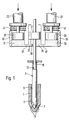
- FIG. 1 shows a first embodiment in a simplified schematic representation, in which the two piezo actuators in the same direction of adjustment via a common hydraulic work area on the Valve member act
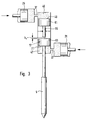
- Figure 2 shows a second embodiment, in which the two electrical actuators in each opposite direction of adjustment via a common hydraulic working space on the valve member of the fuel injector attack
- Figure 3 a third Embodiment analogous to the representation of Figure 2, at a separate hydraulic one for each electric actuator Working space is assigned to the valve member.
- Fuel injection valve for internal combustion engines has one Valve body 1 on, with its lower free end in the combustion chamber, not shown, to be supplied Internal combustion engine protrudes.
- the valve body 1 In the valve body 1 is one axial blind hole 3 is provided, in which a not shown injection line leading away from a fuel injection pump flows.
- a piston-shaped is in the valve body 1
- Valve member 5 is arranged axially displaceable a valve sealing surface 7 at its lower end near the combustion chamber with which it is used to control an injection cross section cooperates with a valve seat surface 9 on the valve body 1, formed at the closed end of the blind hole 3 is. Two lead from the valve seat 9 Injection openings 11 in the combustion chamber to be supplied Internal combustion engine.
- valve member 5 reduces at its the end facing away from the valve sealing surface 7 has its cross section forming an annular shoulder 13 on which one on the other hand, valve spring 15 which is fixed to the housing attacks such that it engages the valve member 5 in the Valve seat 9 holds.
- Valve member 5 is a valve piston enlarged in cross section 17, which for the axial actuation of the valve member 5 protrudes into a hydraulic working space 19 and this with its lower piston ring end face facing the valve seat 9 21 limited.
- electrical actuators are also preferably designed as piezo actuators electrical actuators are provided, a first of which Actuator 23 via an axially adjacent first Adjusting piston 25 also in the hydraulic work space 19 protrudes.
- first actuator 23 is a too this second actuator 27 arranged offset, the also with the interposition of a second Adjusting piston 29 projects into the hydraulic working space 19.
- the hydraulic work space 19 is in three sub-rooms divided, of which a first sub-space 31 from the first adjusting piston 25, a second partial space 33 from the second adjusting piston 29 and a third subspace 35 from the valve piston 17 is limited.
- the third subspace 35 is over each a throttle point 37 with the other two subspaces 31 and 33 connected.
- the first embodiment shown in Figure 1 of the fuel injection valve according to the invention for internal combustion engines works in the following way.
- the adjusting pistons 25 and 29 are through the Return springs 41 in contact with the actuators 23 and 27 held so that in the hydraulic working space 19 only a stand pressure is built up.
- This on the piston ring face 21 of the valve piston fixedly connected to the valve member 5 17 attacking in the opening direction of the valve member 5 Stand pressure is, however, less than the closing force the valve spring 15, which the valve member 5 with its valve sealing surface 7 sealingly on the valve seat 9 that the injection openings 11 from the valve sealing surface 7 be kept closed.
- the actuators 23 and 27 are energized and extend in length.
- the adjusting pistons 25 become more hydraulic in the direction Working space 19 moved so that the hydraulic medium the subspaces 31 and 33 via the throttling points 37 in the third subspace 35 is displaced.
- There the inflowing takes hold hydraulic pressure medium on the end face 21 of the Valve piston 17 and moves it against the Closing force of the valve spring 15 in that facing away from the valve seat 9 Direction so that the valve member 5 from the valve seat 9th takes off and the flow cross-section between that with high pressure fuel filled blind hole 3 to the injection openings 11 releases.
- This causes vibrations on the valve member 5 through a targeted step-like movement of the electrical Actuators 23 and 27 damped.
- the axial expansion adjustment movement of the actuators 23 and 27 triggered gradually, with an actuator short each time is controlled after the second actuator.
- the temporal Displacement of the adjustment movements of the actuators 23 and 27 to each other is about a few 10 ⁇ s.
- the electric actuators 23 and 27 again de-energized so that they are back in very quickly return to their axially shortened starting position. This is done the actuation of the electric actuators 23 and 27 again with a slight time difference.
- the respective Adjusting pistons 25 and 29 are by the force of Return springs 41 also in the direction of actuators 23, 27 moved back so that the volume in the hydraulic The workspace is quickly enlarged and the pressure is quickly reduced the closing pressure of the valve spring 15 drops. Consequently the valve member 5 is in again by the valve spring 15 System moved to the valve seat 9, so that the opening cross section closed again on the fuel injector and the injection is finished.
- This avoidance of cavitation can also be caused by a delay in the reset speed of the electrical Actuators 23 and 27 and by increasing the system pressure in the hydraulic working space 19 well above the Vapor pressure of the hydraulic medium are supported.
- the second embodiment shown in Figure 2 differs from the first one shown in FIG Embodiment in that now two hydraulic Working spaces are provided, which are by the valve piston 17th are so delimited from each other that they are the valve piston 17 of the valve member 5 each in the opposite direction of adjustment act upon.
- the two are hydraulic Workspaces in a common cylindrical Chamber 43 arranged by the slidably guided therein Valve piston 17 in a first upper hydraulic work space 45 and a second lower hydraulic work space 47 is divided.
- a first upper limit Valve piston face 49 the first upper hydraulic Working space 45 and a second lower valve piston end face 21 the second lower hydraulic working space 47 hydraulic work spaces 45 and 47 are each in two Sub-rooms divided, of which a sub-room on the adjusting piston 25, 29 of the electric actuator 23, 27 and another sub-space opens onto the valve piston 17 and the again connected to one another via a throttle cross section 37 are.
- the second embodiment shown in Figure 2 works in the following way.
- the fuel injector is the first actuator 23 axially extended. This can be done by feeding one Control voltage axially expanding piezo element to be energized or a contracting one under supply of a control voltage Piezo element to be de-energized.
- the first actuator 23 becomes the first Adjusting piston 25 in the direction of the first hydraulic working space 45 moved, this adjustment movement of the first Adjusting piston 25 via the upper valve piston end face 49 of the adjusting piston 17 so transmitted to the valve member 5 is that this with its valve sealing surface 7 sealing in System is pressed against the valve seat surface 9.
- the second Actuator 27 is when the fuel injector is closed switched so that it has its smallest axial extent having.
- the second adjusting piston 29 is thereby Return spring 41 held in contact with the actuator 27 and is largely from the second lower hydraulic work space 47 dived.
- the first actuator 23 is now switched so that it reduces its axial extent.
- the second actuator 27 switched such that its axial extension increased, so that the second adjusting piston 29 from the second actuator 27 in the direction of the second lower hydraulic work space 47 is moved.
- This Adjustment movement of the second adjusting piston 29 is hydraulic on the lower piston ring end face 21 of the adjusting piston 17 transmitted so that the valve member 5 from the valve seat 9 is lifted off and the injection cross section in the Releases the combustion chamber of the internal combustion engine.
- the third exemplary embodiment of the fuel injection valve according to the invention shown in FIG. 3 differs from the second exemplary embodiment shown in FIG. 2 by the design of the valve piston 17, which is now formed in two parts.
- a first upper piston part 61 delimits the upper hydraulic working space 45 with its upper valve piston end face 49, which acts on the valve member 5 in the closing direction.
- a second lower piston part 63 of the valve piston 17 delimits, with its lower piston ring end face 21, the lower hydraulic working space 47, which acts in the opening direction on the valve member 5 of the inward opening fuel injection valve.
- the two piston parts 61 and 63 can be brought into contact with one another at a certain distance from one another by a piston rod 65 which is preferably arranged on the upper piston part 61, with a preliminary stroke h v of the valve member 5 in over the free distance between the piston rod 65 and the lower piston part 63 Can open the opening direction.
- the fuel injector shown in FIG. 3 without the actuators and the corresponding return springs of the adjusting pistons works analogously to the second exemplary embodiment.
- the valve member 5 At the beginning of the opening stroke phase, when the second actuator 27 is displaced in the direction of the lower hydraulic working space 47, the valve member 5 first runs through a very rapid forward stroke path h v , in which only the force of the valve spring 15, not shown, has to be overpressed. After traveling through the preliminary stroke path h v , the lower valve piston part 63 comes into contact with the upper valve piston part 61 and now has to overcome a greater restoring force in the course of the further adjustment stroke movement.
- the opening stroke curve of the valve member 5 following the pre-injection can be adjusted by the corresponding actuation of the first actuator 23 which actuates the first adjusting piston 25.
- the hydraulic working spaces 45 and 47 are preferably separated from one another by the valve piston 17.
Landscapes
- Engineering & Computer Science (AREA)
- Physics & Mathematics (AREA)
- Fluid Mechanics (AREA)
- Chemical & Material Sciences (AREA)
- Combustion & Propulsion (AREA)
- Mechanical Engineering (AREA)
- General Engineering & Computer Science (AREA)
- Fuel-Injection Apparatus (AREA)
Abstract
Description
Die Erfindung geht von einem Kraftstoffeinspritzventil für Brennkraftmaschinen nach der Gattung des Patentanspruchs 1 aus. Bei einem solchen aus der DE 195 00 706 A1 bekannten Kraftstoffeinspritzventil ist ein kolbenförmiges Ventilglied axial verschiebbar in einem Ventilkörper angeordnet, der mit seinem freien Ende in den Brennraum der zu versorgenden Brennkraftmaschine ragt. Das Ventilglied weist dabei an seinem brennraumseitigen Ende eine Ventildichtfläche auf, mit der es zur Steuerung eines Einspritzquerschnittes mit einer Ventilsitzfläche am Ventilkörper zusammenwirkt, von der eine Einspritzöffnung in den Brennraum der Brennkraftmaschine abführt. Das Ventilglied wird von einem elektrischen Stellglied, vorzugsweise einem Piezoaktor axial betätigt, wobei die Stellbewegung des Piezoaktors über einen hydraulischen Arbeitsraum auf das Ventilglied übertragen wird. Dies hat dabei den Vorteil, daß z. B. temperaturabhängige Schwankungen des Piezoaktors ausgeglichen werden können und zudem die Stellbewegung des Piezoaktors in eine größere Stellbewegung des Ventilgliedes übersetzt werden kann. The invention relates to a fuel injection valve for Internal combustion engines according to the preamble of claim 1 out. In such a known from DE 195 00 706 A1 Fuel injection valve is a piston-shaped valve member axially slidably disposed in a valve body with its free end in the combustion chamber of the one to be supplied Internal combustion engine protrudes. The valve member points to his end on the combustion chamber side with a valve sealing surface which is used to control an injection cross section with a Valve seat surface cooperates on the valve body, one of which Injection opening leads into the combustion chamber of the internal combustion engine. The valve member is operated by an electrical actuator, preferably axially actuated a piezo actuator, wherein the actuating movement of the piezo actuator via a hydraulic Working space is transferred to the valve member. this has the advantage that z. B. temperature-dependent fluctuations of the piezo actuator can be compensated and also the Actuating movement of the piezo actuator in a larger actuating movement of the valve member can be translated.
Dabei weist das bekannte Kraftstoffeinspritzventil jedoch den Nachteil auf, daß es beim dynamischen Betrieb zu Überschwingungen und Prellern des Ventilgliedes kommen kann, die ein ungewolltes Öffnen des Einspritzventils zur Folge haben. Zudem werden bei dem bekannten Kraftstoffeinspritzventil Eigenschwingungen des Piezoaktors über den hydraulischen Verstärkerraum auf das Ventilglied übertragen, so daß auch dieses zu schwingen beginnt und somit den Einspritzverlauf verfälscht. Ein weiterer Nachteil des bekannten Kraftstoffeinspritzventils tritt bei der Rückstellbewegung des Piezoaktors auf, wobei durch die rasche Volumenvergrößerung des hydraulischen Arbeitsraumes der Druck des darin befindlichen Kraftstoffes unter den Dampfdruck sinken kann und somit Kavitationsschäden auftreten können.However, the known fuel injection valve the disadvantage that there are overshoots in dynamic operation and bouncing of the valve member can come result in an unwanted opening of the injection valve. In addition, natural vibrations occur in the known fuel injection valve of the piezo actuator via the hydraulic amplifier room transferred to the valve member, so that this too begins to oscillate and thus falsifies the injection process. Another disadvantage of the known fuel injection valve occurs during the reset movement of the piezo actuator on, with the rapid increase in volume of the hydraulic Working space the pressure of the inside Fuel can drop below the vapor pressure and thus cavitation damage may occur.
Das erfindungsgemäße Kraftstoffeinspritzventil für Brennkraftmaschinen mit den kennzeichnenden Merkmalen des Patentanspruchs 1 hat demgegenüber den Vorteil, daß durch die Verwendung eines zweiten elektrischen Stellgliedes eine sehr schnelle und direkte Ventilgliedbetätigung möglich ist, mit der sich der Einspritzöffnungsquerschnitt und somit der Einspritzverlauf am Kraftstoffeinspritzventil optimal über die Einspritzzeit formen läßt. Dabei erfolgt der mechanische bzw. Temperaturausgleich des Piezoaktors sowie die hydraulische Verstärkung der Verstellbewegung des Piezoaktors über einen hydraulischen Arbeitsraum. Dieser Arbeitsraum ist dabei in zwei Teilräume unterteilt, die jeweils durch einen Kolben des Piezoaktors und des Ventilgliedes begrenzt werden und die über eine Drosselstelle voneinander getrennt sind, so daß am Piezoaktor auftretende Schwingungen nicht auf das Ventilglied übertragen werden und ein Überschwingen bzw. Preller am Ventilglied selbst unterdrückt werden. Durch die Trennung von elektrischem Stellglied und dessen Verstellkolben wird zudem das Entstehen eines Unterdruckes bei schnellem Rückstellen der elektrischen Stellglieder vermieden, wobei diese dann vom Verstellkolben abheben. Besonders vorteilhaft ist die Verwendung von zwei in Gegenrichtung auf das Ventilglied wirkenden elektrischen Stellgliedern, da somit neben einem sehr schnellen und gesteuerten Öffnungshub auch der Schließhub des Ventilgliedes sehr rasch und gesteuert ausgeführt werden kann. Dabei kann durch die Verwendung dieser in Gegenrichtung wirkenden elektrischen Stellglieder auch eine Dämpfung des Ventilgliedes erreicht werden, da der zweite in Gegenrichtung zum ersten wirkende Aktor einen dynamischen Kräfteausgleich im hydraulischen Arbeitsraum bewirkt. Ein weiterer Vorteil wird durch die zweiteilige Ausbildung des mit dem Ventilglied verbundenen Ventilkolbens erreicht, bei der jeder Ventilkolbenteil einen in Gegenrichtung auf das Ventilglied wirkenden Arbeitsraum begrenzt. Dabei läßt sich durch einen vorgegebenen Abstand zwischen den beiden Kolbenteilen ein Vorhub am Ventilglied realisieren.The fuel injection valve according to the invention for internal combustion engines with the characterizing features of the claim 1 has the advantage that the use a second electrical actuator a very fast and direct valve member actuation is possible with which is the cross section of the injection opening and thus the course of the injection on the fuel injection valve optimally over the Injection time forms. The mechanical one takes place or temperature compensation of the piezo actuator and the hydraulic Amplification of the adjustment movement of the piezo actuator via a hydraulic work area. This work space is included divided into two sub-rooms, each by one Pistons of the piezo actuator and the valve member are limited and which are separated from each other by a throttling point, so that vibrations occurring at the piezo actuator do not affect the Valve element are transmitted and an overshoot or Bouncers on the valve member itself are suppressed. Through the Separation of the electric actuator and its adjusting piston will also create a negative pressure at fast Resetting the electrical actuators avoided, whereby then lift them off the adjusting piston. Particularly advantageous is the use of two in the opposite direction the valve actuator acting electrical actuators, because thus in addition to a very fast and controlled opening stroke the closing stroke of the valve member is very quick and controlled can be executed. This can be done by using this electrical actuators acting in the opposite direction damping of the valve member can also be achieved since the second actuator acting in the opposite direction to the first one dynamic Equalization of forces in the hydraulic work area. Another advantage is the two-part training of the valve piston connected to the valve member reached, in which each valve piston part one in the opposite direction limited working space acting on the valve member. Here can be determined by a predetermined distance between the Realize a forward stroke on the valve member for both piston parts.
Durch eine gezielte stufenförmige Verstellbewegung der elektrischen Stellglieder ist es zudem möglich, ein Schwingen des Ventilgliedes zu unterdrücken bzw. zu dämpfen.Through a targeted step-like adjustment movement of the electrical Actuators are also able to swing to suppress or dampen the valve member.
Das elektrische Stellglied kann dabei alternativ als piezoelektrischer oder magnetostriktiver Aktor ausgebildet sein. Zudem kann das von den elektrischen Stellgliedern betägtigte Kraftstoffeinspritzventil als nach außen öffnendes Einspritzventils oder nach innen öffnendes Einspritzventil, z. B. Loch- oder Zapfendüse ausgebildet sein.The electrical actuator can alternatively as a piezoelectric or magnetostrictive actuator. In addition, that actuated by the electrical actuators Fuel injection valve as an outward opening injection valve or inward opening injection valve, e.g. B. hole or tenon nozzle.
Weitere Vorteile und vorteilhafte Ausgestaltungen des Gegenstandes der Erfindung sind der Beschreibung, der Zeichnung und den Patentansprüchen entnehmbar. Further advantages and advantageous configurations of the object the invention are the description, the drawing and the patent claims.
Drei Ausführungsbeispiele des erfindungsgemäßen Kraftstoffeinspritzventils für Brennkraftmaschinen sind in der Zeichnung dargestellt und werden in der nachfolgenden Beschreibung näher erläutert. Es zeigen die Figur 1 ein erstes Ausführungsbeispiel in einer vereinfachten Schemadarstellung, bei dem die beiden Piezoaktoren in gleicher Verstellrichtung über einen gemeinsamen hydraulischen Arbeitsraum auf das Ventilglied wirken, die Figur 2 ein zweites Ausführungsbeispiel, bei dem die beiden elektrischen Stellglieder in jeweils entgegengesetzter Verstellrichtung über einen gemeinsamen hydraulischen Arbeitsraum am Ventilglied des Kraftstoffeinspritzventils angreifen, und die Figur 3 ein drittes Ausführungsbeispiel analog zur Darstellung der Figur 2, bei dem jedem elektrischen Stellglied ein separater hydraulischer Arbeitsraum zum Ventilglied zugeordnet ist.Three embodiments of the fuel injection valve according to the invention for internal combustion engines are in the drawing are shown and are described in the following description explained in more detail. 1 shows a first embodiment in a simplified schematic representation, in which the two piezo actuators in the same direction of adjustment via a common hydraulic work area on the Valve member act, Figure 2 shows a second embodiment, in which the two electrical actuators in each opposite direction of adjustment via a common hydraulic working space on the valve member of the fuel injector attack, and Figure 3 a third Embodiment analogous to the representation of Figure 2, at a separate hydraulic one for each electric actuator Working space is assigned to the valve member.
Das in der Figur 1 in einer vereinfachten Schemadarstellung
gezeigte erste Ausführungsbeispiel des erfindungsgemäßen
Kraftstoffeinspritzventils für Brennkraftmaschinen weist einen
Ventilkörper 1 auf, der mit seinem unteren freien Ende
in den nicht näher dargestellten Brennraum der zu versorgenden
Brennkraftmaschine ragt. Im Ventilkörper 1 ist eine
axiale Sackbohrung 3 vorgesehen, in die eine nicht gezeigte,
von einer Kraftstoffeinspritzpumpe abführende Einspritzleitung
mündet. Desweiteren ist im Ventilkörper 1 ein kolbenförmiges
Ventilglied 5 axial verschiebbar angeordnet, das an
seinem unteren, brennraumnahen Ende eine Ventildichtfläche 7
aufweist, mit der es zur Steuerung eines Einspritzquerschnittes
mit einer Ventilsitzfläche 9 am Ventilkörper 1 zusammenwirkt,
die am geschlossenen Ende der Sackbohrung 3 gebildet
ist. Dabei führen von der Ventilsitzfläche 9 zwei
Einspritzöffnungen 11 in den Brennraum der zu versorgenden
Brennkraftmaschine ab. Das Ventilglied 5 verringert an seinem
der Ventildichtfläche 7 abgewandten Ende seinen Querschnitt
unter Bildung einer Ringschulter 13, an der eine
sich andererseits gehäusefest abstützende Ventilfeder 15
derart angreift, daß sie das Ventilglied 5 in Anlage an der
Ventilsitzfläche 9 hält.1 in a simplified schematic representation
shown first embodiment of the invention
Fuel injection valve for internal combustion engines has one
Valve body 1 on, with its lower free end
in the combustion chamber, not shown, to be supplied
Internal combustion engine protrudes. In the valve body 1 is one
axial
An seinem der Ventildichtfläche 7 abgewandten Ende weist das
Ventilglied 5 einen im Querschnitt vergrößerten Ventilkolben
17 auf, der zur axialen Betätigung des Ventilgliedes 5
in einen hydraulischen Arbeitsraum 19 ragt und diesen mit
seiner unteren, dem Ventilsitz 9 zugewandten Kolbenringstirnfläche
21 begrenzt. Zur Betätigung des Ventilgliedes 5
sind weiterhin zwei vorzugsweise als Piezoaktoren ausgebildete
elektrische Stellglieder vorgesehen, von denen ein erstes
Stellglied 23 über einen axial daran anliegenden ersten
Verstellkolben 25 ebenfalls in den hydraulischen Arbeitsraum
19 ragt. Zusätzlich zum ersten Stellglied 23 ist ein zu
diesem versetzt angeordnetes zweites Stellglied 27 vorgesehen,
das ebenfalls unter Zwischenschaltung eines zweiten
Verstellkolbens 29 in den hydraulischen Arbeitsraum 19 ragt.
Dabei ist der hydraulische Arbeitsraum 19 in drei Teilräume
unterteilt, von denen ein erster Teilraum 31 vom ersten Verstellkolben
25, ein zweiter Teilraum 33 vom zweiten Verstellkolben
29 und ein dritter Teilraum 35 vom Ventilkolben
17 begrenzt ist. Dabei ist der dritte Teilraum 35 über
jeweils eine Drosselstelle 37 mit den beiden anderen Teilräumen
31 und 33 verbunden.At its end facing away from the
Für eine sichere ständige Anlage der Verstellkolben 25 und
29 an den elektrischen Stellgliedern 23 und 27 sind zwischen
den Verstellkolben 25 und 29 und dem diese führenden Gehäuse
Rückstellfedern 41 eingespannt, die die Verstellkolben 25
und 29 in vom hydraulischen Arbeitsraum 19 abgewandter Richtung
beaufschlagen und diese so in ständiger Anlage an den
elektrischen Stellgliedern 23 und 27 halten.For a safe permanent system of the adjusting
Das in der Figur 1 dargestellte erste Ausführungsbeispiel
des erfindungsgemäßen Kraftstoffeinspritzventils für Brennkraftmaschinen
arbeitet in folgender Weise. In Ausgangslage
des geschlossenen Kraftstoffeinspritzventils sind die als
Piezoaktoren ausgebildeten elektrischen Stellglieder 23 und
27 stromlos geschalten und weisen ihre kleinste axiale Erstreckung
auf. Die Verstellkolben 25 und 29 sind durch die
Rückstellfedern 41 in Anlage an den Stellgliedern 23 und 27
gehalten, so daß im hydraulischen Arbeitsraum 19 lediglich
ein Standdruck aufgebaut ist. Dieser an der Kolbenringstirnfläche
21 des fest mit dem Ventilglied 5 verbundenen Ventilkolben
17 in Öffnungsrichtung des Ventilgliedes 5 angreifende
Standdruck ist dabei jedoch kleiner als die Schließkraft
der Ventilfeder 15, die das Ventilglied 5 mit seiner Ventildichtfläche
7 dichtend an der Ventilsitzfläche 9 hält, so
daß die Einspritzöffnungen 11 von der Ventildichtfläche 7
verschlossen gehalten werden. Soll eine Einspritzung am
Kraftstoffeinspritzventil erfolgen, werden die Stellglieder
23 und 27 bestromt und dehnen sich in ihrer Länge aus.
Dabei werden die Verstellkolben 25 in Richtung hydraulischer
Arbeitsraum 19 verschoben, so daß das Hydraulikmedium aus
den Teilräumen 31 und 33 über die Drosselstellen 37 in den
dritten Teilraum 35 verdrängt wird. Dort greift das zuströmende
hydraulische Druckmittel an der Stirnfläche 21 des
Ventilkolbens 17 an und verschiebt diesen entgegen der
Schließkraft der Ventilfeder 15 in die vom Ventilsitz 9 abgewandte
Richtung, so daß das Ventilglied 5 vom Ventilsitz 9
abhebt und den Durchströmquerschnitt zwischen der mit Hochdruckkraftstoff
gefüllten Sackbohrung 3 zu den Einspritzöffnungen
11 freigibt. Dabei werden Schwingungen am Ventilglied
5 durch eine gezielte stufenförmige Bewegung der elektrischen
Stellglieder 23 und 27 gedämpft. Dazu wird die
axiale Ausdehnungsstellbewegung der Stellglieder 23 und 27
stufenweise ausgelöst, wobei ein Stellglied jeweils kurz
nach dem zweiten Stellglied angesteuert wird. Die zeitliche
Verschiebung der Verstellbewegungen der Stellglieder 23 und
27 zueinander beträgt dabei etwa einige 10 µs.The first embodiment shown in Figure 1
of the fuel injection valve according to the invention for internal combustion engines
works in the following way. In the starting position
of the closed fuel injector are the as
Piezoactuators trained
Zur Beendigung des Einspritzvorganges am Kraftstoffeinspritzventil
werden die elektrischen Stellglieder 23 und 27
erneut stromlos geschaltet, so daß sie wieder sehr rasch in
ihre axial verkürzte Ausgangslage zurückkehren. Dabei erfolgt
das Ansteuern der elektrischen Stellglieder 23 und 27
erneut mit einer geringen zeitlichen Verschiebung. Die jeweiligen
Verstellkolben 25 und 29 werden durch die Kraft der
Rückstellfedern 41 ebenfalls in Richtung Stellglieder 23, 27
zurückverschoben, so daß sich das Volumen im hydraulischen
Arbeitsraum rasch vergrößert und der Druck somit schnell unter
den Schließdruck der Ventilfeder 15 absinkt. Infolgedessen
wird das Ventilglied 5 von der Ventilfeder 15 erneut in
Anlage an den Ventilsitz 9 verschoben, so daß der Öffnungsquerschnitt
am Kraftstoffeinspritzventil wieder verschlossen
und die Einspritzung beendet ist. Dabei wird durch die Trennung
der Verstellkolben 25, 29 von den elektrischen Stellgliedern
23 und 27 die Rückstellbewegung der Verstellkolben
25 und 29 derart verzögert, daß der Druck im hydraulischen
Arbeitsraum nicht unter den Dampfdruck abfällt und somit
keine Kavitationsschäden auslösende Unterdruckgebiete
entstehen. Diese Vermeidung von Kavitation kann zudem durch
eine Verzögerung der Rückstellgeschwindigkeit der elektrischen
Stellglieder 23 und 27 und durch eine Erhöhung des Systemdruckes
im hydraulischen Arbeitsraum 19 weit über den
Dampfdruck des hydraulischen Mediums unterstützt werden.To end the injection process on the fuel injector
the
Das in der Figur 2 dargestellte zweite Ausführungsbeispiel
unterscheidet sich vom in der Figur 1 dargestellten ersten
Ausführungsbeispiel dadurch, daß nunmehr zwei hydraulische
Arbeitsräume vorgesehen sind, die durch den Ventilkolben 17
derart voneinander abgegrenzt sind, daß sie den Ventilkolben
17 des Ventilgliedes 5 jeweils in entgegengesetzter Verstellrichtung
beaufschlagen. Dazu sind die zwei hydraulischen
Arbeitsräume in einer gemeinsamen zylinderförmigen
Kammer 43 angeordnet, die durch den gleitend darin geführten
Ventilkolben 17 in einen ersten oberen hydraulischen Arbeitsraum
45 und einen zweiten unteren hydraulischen Arbeitsraum
47 unterteilt ist. Dabei begrenzt eine erste obere
Ventilkolbenstirnfläche 49 den ersten oberen hydraulischen
Arbeitsraum 45 und eine zweite untere Ventilkolbenstirnfläche
21 den zweiten unteren hydraulischen Arbeitsraum 47. Die
hydraulischen Arbeiträume 45 und 47 sind jeweils in zwei
Teilräume unterteilt, von denen je ein Teilraum an den Verstellkolben
25, 29 des elektrischen Stellgliedes 23, 27 und
ein anderer Teilraum an den Ventilkolben 17 mündet und die
wiederum über einen Drosselquerschnitt 37 miteinander verbunden
sind.The second embodiment shown in Figure 2
differs from the first one shown in FIG
Embodiment in that now two hydraulic
Working spaces are provided, which are by the valve piston 17th
are so delimited from each other that they are the
Das in der Figur 2 dargestellte zweite Ausführungsbeispiel
arbeitet in folgender Weise. In Ausgangslage bei geschlossenem
Kraftstoffeinspritzventil ist das erste Stellglied 23
axial ausgedehnt. Dazu kann ein sich unter Zuführung einer
Steuerspannung axial ausdehnendes Piezoelement bestromt sein
oder ein sich unter Zuführung einer Steuerspannung zusammenziehendes
Piezoelement stromlos geschaltet sein. Durch die
axiale Ausdehnung des ersten Stellgliedes 23 wird der erste
Verstellkolben 25 in Richtung erster hydraulischer Arbeitsraum
45 verschoben, wobei diese Verstellbewegung des ersten
Verstellkolbens 25 über die obere Ventilkolbenstirnfläche 49
des Verstellkolbens 17 so auf das Ventilglied 5 übertragen
wird, daß dieses mit seiner Ventildichtfläche 7 dichtend in
Anlage an die Ventilsitzfläche 9 gepreßt wird. Das zweite
Stellglied 27 ist bei geschlossenem Kraftstoffeinspritzventil
so geschaltet, daß es seine kleinste axiale Erstreckung
aufweist. Der zweite Verstellkolben 29 wird dabei durch die
Rückstellfeder 41 in Anlage am Stellglied 27 gehalten und
ist weitgehend aus dem zweiten unteren hydraulischen Arbeitsraum
47 ausgetaucht.The second embodiment shown in Figure 2
works in the following way. In the starting position with the door closed
The fuel injector is the
Soll eine Einspritzung am Kraftstoffeinspritzventil erfolgen,
wird nunmehr das erste Stellglied 23 so geschaltet, daß
es seine axiale Erstreckung verringert. Gleichzeitig wird
das zweite Stellglied 27 derart geschaltet, daß sich seine
axiale Erstreckung vergrößert, so daß der zweite Verstellkolben
29 vom zweiten Stellglied 27 in Richtung zweiter unterer
hydraulischer Arbeitsraum 47 verschoben wird. Diese
Stellbewegung des zweiten Verstellkolbens 29 wird hydraulisch
auf die untere Kolbenringstirnfläche 21 des Verstellkolbens
17 übertragen, so daß das Ventilglied 5 vom Ventilsitz
9 abgehoben wird und den Einspritzquerschnitt in den
Brennraum der Brennkraftmaschine freigibt. Um dabei Schwingungen
am Ventilglied 5 zu vermeiden kann die Verstellung
des Ventilgliedes erneut durch ein stufenweises Ansteuern
der Stellglieder 23 und 27 erfolgen, wobei der in Schließrichtung
wirkende Verstellkolben 25 jeweils kurzzeitig vom
Stellglied 23 in seiner Lage fixiert wird und so kurzzeitig
eine dämpfende Gegenkraft aufbaut. Dabei werden zudem durch
den Drosseleffekt an den Drosselstellen 37 die Übertragung
von Eigenschwingungen der Stellglieder 23 und 27 gedämpft.If the fuel injection valve is to be injected,
the
Das in der Figur 3 dargestellte dritte Ausführungsbeispiel
des erfindungsgemäßen Kraftstoffeinspritzventils unterscheidet
sich zum in der Figur 2 dargestellten zweiten Ausführungsbeispiel
durch die Ausbildung des Ventilkolbens 17, der
nunmehr zweiteilig ausgebildet ist. Dabei begrenzt ein erster
oberer Kolbenteil 61 mit seiner oberen Ventilkolbenstirnfläche
49 den oberen hydraulischen Arbeitsraum 45, der
in Schließrichtung auf das Ventilglied 5 wirkt. Ein zweiter
unterer Kolbenteil 63 des Ventilkolbens 17 begrenzt mit seiner
unteren Kolbenringstirnfläche 21 den unteren hydraulischen
Arbeitsraum 47, der in Öffnungsrichtung auf das Ventilglied
5 des nach innen öffnenden Kraftstoffeinspritzventils
wirkt. Die beiden Kolbenteile 61 und 63 sind durch eine
vorzugsweise am oberen Kolbenteil 61 angeordnete Kolbenstange
65 in einem bestimmten Abstand zueinander miteinander in
Anlage bringbar, wobei sich über den freien Abstand zwischen
der Kolbenstange 65 und dem unteren Kolbenteil 63 ein Vorhub
hv des Ventilgliedes 5 in Öffnungsrichtung einstellen
läßt.The third exemplary embodiment of the fuel injection valve according to the invention shown in FIG. 3 differs from the second exemplary embodiment shown in FIG. 2 by the design of the
Das in der Figur 3 ohne die Stellglieder und die entsprechenden
Rückstellfedern der Verstellkolben dargestellte
Kraftstoffeinspritzventil arbeitet analog zum zweiten Ausführungsbeispiel.
Dabei durchläuft das Ventilglied 5 zu Beginn
der Öffnungshubphase bei Verschieben des zweiten Stellgliedes
27 in Richtung unterer hydraulischer Arbeitsraum 47
zunächst einen sehr raschen Vorhubweg hv, bei dem lediglich
die Kraft der nicht dargestellten Ventilfeder 15 überdrückt
werden muß. Nach Durchfahren des Vorhubweges hv gelangt der
untere Ventilkolbenteil 63 in Anlage an den oberen Ventilkolbenteil
61 und hat nunmehr im Verlauf der weiteren Verstellhubbewegung
eine größere Rückstellkraft zu überwinden.
Dabei kann der sich an die Voreinspritzung anschließende
Öffnungshubverlauf des Ventilgliedes 5 durch die entsprechende
Ansteuerung des den ersten Verstellkolben 25 betätigende
erste Stellglied 23 eingestellt werden. Um dabei eine
gegenseitige Beeinflussung der Stellbewegung der Kolbenteile
61 und 63 zu vermeiden, sind die hydraulischen Arbeitsräume
45 und 47 durch den Ventilkolben 17 vorzugsweise voneinander
getrennt.The fuel injector shown in FIG. 3 without the actuators and the corresponding return springs of the adjusting pistons works analogously to the second exemplary embodiment. At the beginning of the opening stroke phase, when the
Claims (9)
Applications Claiming Priority (2)
| Application Number | Priority Date | Filing Date | Title |
|---|---|---|---|
| DE19709795 | 1997-03-10 | ||
| DE19709795A DE19709795A1 (en) | 1997-03-10 | 1997-03-10 | Fuel injection valve for internal combustion engines |
Publications (3)
| Publication Number | Publication Date |
|---|---|
| EP0864743A2 true EP0864743A2 (en) | 1998-09-16 |
| EP0864743A3 EP0864743A3 (en) | 2001-08-08 |
| EP0864743B1 EP0864743B1 (en) | 2003-06-11 |
Family
ID=7822845
Family Applications (1)
| Application Number | Title | Priority Date | Filing Date |
|---|---|---|---|
| EP97120314A Expired - Lifetime EP0864743B1 (en) | 1997-03-10 | 1997-11-20 | Fuel injection valve for internal combustion engines |
Country Status (3)
| Country | Link |
|---|---|
| EP (1) | EP0864743B1 (en) |
| JP (1) | JPH10252598A (en) |
| DE (2) | DE19709795A1 (en) |
Cited By (15)
| Publication number | Priority date | Publication date | Assignee | Title |
|---|---|---|---|---|
| WO2000017508A1 (en) * | 1998-09-23 | 2000-03-30 | Robert Bosch Gmbh | Fuel injection valve |
| WO2000017510A1 (en) * | 1998-09-23 | 2000-03-30 | Robert Bosch Gmbh | Fuel injection valve |
| WO2001029403A1 (en) * | 1999-10-21 | 2001-04-26 | Robert Bosch Gmbh | Fuel injection valve |
| WO2002053958A1 (en) * | 2001-01-05 | 2002-07-11 | Robert Bosch Gmbh | Valve for controlling liquids |
| EP1167746A3 (en) * | 2000-06-22 | 2003-12-10 | Nippon Soken, Inc. | Fuel injection device |
| DE10333427B3 (en) * | 2003-07-24 | 2004-08-26 | Robert Bosch Gmbh | Fuel injection system for internal combustion engine receives high-pressure fuel from common rail which passes to injection valve and working space under piston |
| DE10333693B3 (en) * | 2003-07-24 | 2004-09-30 | Robert Bosch Gmbh | Fuel injection device for an internal combustion engine comprises a filling chamber arranged between two pistons and connected to a feed line |
| DE10333573B3 (en) * | 2003-07-24 | 2004-11-18 | Robert Bosch Gmbh | Fuel injection arrangement has hydraulic coupler piston(s) with central fill volume connected to guide gap and to fuel feed line, one piston fixed to actuator and one to valve needle via piston rod |
| WO2005026531A1 (en) * | 2003-09-10 | 2005-03-24 | Siemens Aktiengesellschaft | Injection valve for injecting fuel into an internal combustion engine |
| WO2006128751A1 (en) * | 2005-05-30 | 2006-12-07 | Robert Bosch Gmbh | Common rail injector |
| EP2500550A1 (en) * | 2011-03-16 | 2012-09-19 | Siemens Aktiengesellschaft | Stroke transmitter for gas turbine |
| WO2013087475A1 (en) * | 2011-12-12 | 2013-06-20 | Continental Automotive Gmbh | Injection valve |
| WO2015044420A2 (en) * | 2013-09-27 | 2015-04-02 | Siemens Aktiengesellschaft | Lifting system, method for electrical testing, vibration damper, and machine assembly |
| WO2016045989A1 (en) * | 2014-09-26 | 2016-03-31 | Siemens Aktiengesellschaft | Lifting system, method for electrical testing, vibration damper, and machine assembly |
| CN110440046A (en) * | 2019-09-06 | 2019-11-12 | 厦门赛尔特电子有限公司 | A kind of liquid transmitting stroke amplifying type Piezoelectric switches valve |
Families Citing this family (6)
| Publication number | Priority date | Publication date | Assignee | Title |
|---|---|---|---|---|
| JP5024322B2 (en) * | 2009-03-25 | 2012-09-12 | 株式会社デンソー | Fuel injection valve |
| JP5024321B2 (en) * | 2009-03-25 | 2012-09-12 | 株式会社デンソー | Fuel injection valve |
| JP5024320B2 (en) * | 2009-03-25 | 2012-09-12 | 株式会社デンソー | Fuel injection valve |
| KR101314991B1 (en) * | 2012-01-25 | 2013-10-04 | 홍종한 | Piezo injector for vehicle |
| US20160377040A1 (en) * | 2015-06-24 | 2016-12-29 | Great Plains Diesel Technologies, L.C. | Fuel injection rate modulation by magnetostrictive actuator and fluidomechanical coupler |
| GB2560513A (en) * | 2017-03-13 | 2018-09-19 | Ap Moeller Maersk As | Fuel injection system |
Citations (1)
| Publication number | Priority date | Publication date | Assignee | Title |
|---|---|---|---|---|
| DE19500706A1 (en) | 1995-01-12 | 1996-07-18 | Bosch Gmbh Robert | Metering valve for dosing liquids or gases |
Family Cites Families (3)
| Publication number | Priority date | Publication date | Assignee | Title |
|---|---|---|---|---|
| DE3344229A1 (en) * | 1983-12-07 | 1985-06-20 | Pierburg Gmbh & Co Kg, 4040 Neuss | ELECTROMAGNETIC FUEL INJECTION VALVE |
| DE4306072C2 (en) * | 1993-02-26 | 1994-12-08 | Siemens Ag | Device for opening and closing a passage opening in a housing |
| US5669355A (en) * | 1994-07-29 | 1997-09-23 | Caterpillar Inc. | Hydraulically-actuated fuel injector with direct control needle valve |
-
1997
- 1997-03-10 DE DE19709795A patent/DE19709795A1/en not_active Withdrawn
- 1997-11-20 EP EP97120314A patent/EP0864743B1/en not_active Expired - Lifetime
- 1997-11-20 DE DE59710265T patent/DE59710265D1/en not_active Expired - Fee Related
-
1998
- 1998-03-06 JP JP10055345A patent/JPH10252598A/en active Pending
Patent Citations (1)
| Publication number | Priority date | Publication date | Assignee | Title |
|---|---|---|---|---|
| DE19500706A1 (en) | 1995-01-12 | 1996-07-18 | Bosch Gmbh Robert | Metering valve for dosing liquids or gases |
Cited By (23)
| Publication number | Priority date | Publication date | Assignee | Title |
|---|---|---|---|---|
| WO2000017508A1 (en) * | 1998-09-23 | 2000-03-30 | Robert Bosch Gmbh | Fuel injection valve |
| WO2000017510A1 (en) * | 1998-09-23 | 2000-03-30 | Robert Bosch Gmbh | Fuel injection valve |
| US6460779B1 (en) | 1998-09-23 | 2002-10-08 | Robert Bosch Gmbh | Fuel injection valve |
| WO2001029403A1 (en) * | 1999-10-21 | 2001-04-26 | Robert Bosch Gmbh | Fuel injection valve |
| US6685105B1 (en) | 1999-10-21 | 2004-02-03 | Robert Bosch Gmbh | Fuel injection valve |
| EP1167746A3 (en) * | 2000-06-22 | 2003-12-10 | Nippon Soken, Inc. | Fuel injection device |
| WO2002053958A1 (en) * | 2001-01-05 | 2002-07-11 | Robert Bosch Gmbh | Valve for controlling liquids |
| DE10333427B3 (en) * | 2003-07-24 | 2004-08-26 | Robert Bosch Gmbh | Fuel injection system for internal combustion engine receives high-pressure fuel from common rail which passes to injection valve and working space under piston |
| DE10333693B3 (en) * | 2003-07-24 | 2004-09-30 | Robert Bosch Gmbh | Fuel injection device for an internal combustion engine comprises a filling chamber arranged between two pistons and connected to a feed line |
| DE10333573B3 (en) * | 2003-07-24 | 2004-11-18 | Robert Bosch Gmbh | Fuel injection arrangement has hydraulic coupler piston(s) with central fill volume connected to guide gap and to fuel feed line, one piston fixed to actuator and one to valve needle via piston rod |
| WO2005026531A1 (en) * | 2003-09-10 | 2005-03-24 | Siemens Aktiengesellschaft | Injection valve for injecting fuel into an internal combustion engine |
| WO2006128751A1 (en) * | 2005-05-30 | 2006-12-07 | Robert Bosch Gmbh | Common rail injector |
| EP2500550A1 (en) * | 2011-03-16 | 2012-09-19 | Siemens Aktiengesellschaft | Stroke transmitter for gas turbine |
| WO2012123264A1 (en) * | 2011-03-16 | 2012-09-20 | Siemens Aktiengesellschaft | Stroke transmitter for gas turbine |
| CN103459808A (en) * | 2011-03-16 | 2013-12-18 | 西门子公司 | Stroke transmitter for gas turbine |
| CN103459808B (en) * | 2011-03-16 | 2016-03-30 | 西门子公司 | For the stroke transmitter of gas turbine |
| US10156191B2 (en) | 2011-03-16 | 2018-12-18 | Siemens Aktiengesellschaft | Stroke transmitter for gas turbine |
| WO2013087475A1 (en) * | 2011-12-12 | 2013-06-20 | Continental Automotive Gmbh | Injection valve |
| WO2015044420A2 (en) * | 2013-09-27 | 2015-04-02 | Siemens Aktiengesellschaft | Lifting system, method for electrical testing, vibration damper, and machine assembly |
| WO2015044420A3 (en) * | 2013-09-27 | 2015-05-21 | Siemens Aktiengesellschaft | Lifting system, method for electrical testing, vibration damper, and machine assembly |
| US10355622B2 (en) | 2013-09-27 | 2019-07-16 | Siemens Aktiengesellschaft | Lifting system, method for electrical testing, vibration damper, and machine assembly |
| WO2016045989A1 (en) * | 2014-09-26 | 2016-03-31 | Siemens Aktiengesellschaft | Lifting system, method for electrical testing, vibration damper, and machine assembly |
| CN110440046A (en) * | 2019-09-06 | 2019-11-12 | 厦门赛尔特电子有限公司 | A kind of liquid transmitting stroke amplifying type Piezoelectric switches valve |
Also Published As
| Publication number | Publication date |
|---|---|
| EP0864743A3 (en) | 2001-08-08 |
| DE19709795A1 (en) | 1998-09-17 |
| JPH10252598A (en) | 1998-09-22 |
| EP0864743B1 (en) | 2003-06-11 |
| DE59710265D1 (en) | 2003-07-17 |
Similar Documents
| Publication | Publication Date | Title |
|---|---|---|
| EP0864743B1 (en) | Fuel injection valve for internal combustion engines | |
| EP1636484B1 (en) | Injector for internal combustion engines | |
| DE19531652A1 (en) | Fuel injection valve for internal combustion engines | |
| EP1853813B1 (en) | Injection nozzle | |
| DE19709794A1 (en) | Valve for controlling liquids | |
| DE19546033A1 (en) | Fuel injection valve for internal combustion engines | |
| DE2931874A1 (en) | ELECTRICALLY OPERATED VALVE | |
| DE60125304T2 (en) | ADJUSTABLE LIFTING DEVICE FOR A FUEL INJECTION VALVE | |
| DE19918976A1 (en) | Fuel injector and method for actuating it | |
| DE19739905A1 (en) | Fuel injector | |
| WO2007014793A1 (en) | Injection nozzle | |
| EP1402174B1 (en) | Fuel injection device for an internal combustion engine | |
| DE19907348A1 (en) | Vehicle engine fuel injection valve, with fuel transfer achieved by springs which are stressed by valve member in opening stroke | |
| EP0872636A2 (en) | Fuel injection valve for internal combustion engines | |
| EP1658427B1 (en) | Fuel injection valve for internal combustion engines | |
| EP2458194B1 (en) | Fuel injector valve for combustion engines | |
| EP2426348B1 (en) | Fuel injector valve | |
| DE102005026979A1 (en) | Fuel injector, has servo-valve unit including stem, sealing hub, and closure unit, for decoupling hydraulic closing force from fuel pressure acting in operating chamber, where force is caused during opening of closure unit | |
| DE102006036782B4 (en) | injector | |
| EP1519034B1 (en) | Fuel injection valve | |
| DE102009002897A1 (en) | fuel injector | |
| DE102004045393B4 (en) | Fuel injector | |
| DE102005024721B4 (en) | Common rail injector | |
| DE10019767A1 (en) | Valve for controlling liquids | |
| EP1406006B1 (en) | Fuel injection valve |
Legal Events
| Date | Code | Title | Description |
|---|---|---|---|
| PUAI | Public reference made under article 153(3) epc to a published international application that has entered the european phase |
Free format text: ORIGINAL CODE: 0009012 |
|
| AK | Designated contracting states |
Kind code of ref document: A2 Designated state(s): DE FR GB IT |
|
| AX | Request for extension of the european patent |
Free format text: AL;LT;LV;MK;RO;SI |
|
| PUAL | Search report despatched |
Free format text: ORIGINAL CODE: 0009013 |
|
| AK | Designated contracting states |
Kind code of ref document: A3 Designated state(s): AT BE CH DE DK ES FI FR GB GR IE IT LI LU MC NL PT SE |
|
| AX | Request for extension of the european patent |
Free format text: AL;LT;LV;MK;RO;SI |
|
| 17P | Request for examination filed |
Effective date: 20020208 |
|
| AKX | Designation fees paid |
Free format text: DE FR GB IT |
|
| GRAH | Despatch of communication of intention to grant a patent |
Free format text: ORIGINAL CODE: EPIDOS IGRA |
|
| GRAH | Despatch of communication of intention to grant a patent |
Free format text: ORIGINAL CODE: EPIDOS IGRA |
|
| GRAA | (expected) grant |
Free format text: ORIGINAL CODE: 0009210 |
|
| AK | Designated contracting states |
Designated state(s): DE FR GB IT |
|
| REG | Reference to a national code |
Ref country code: GB Ref legal event code: FG4D Free format text: NOT ENGLISH |
|
| REF | Corresponds to: |
Ref document number: 59710265 Country of ref document: DE Date of ref document: 20030717 Kind code of ref document: P |
|
| GBT | Gb: translation of ep patent filed (gb section 77(6)(a)/1977) |
Effective date: 20031006 |
|
| PG25 | Lapsed in a contracting state [announced via postgrant information from national office to epo] |
Ref country code: GB Free format text: LAPSE BECAUSE OF NON-PAYMENT OF DUE FEES Effective date: 20031120 |
|
| ET | Fr: translation filed | ||
| PLBE | No opposition filed within time limit |
Free format text: ORIGINAL CODE: 0009261 |
|
| STAA | Information on the status of an ep patent application or granted ep patent |
Free format text: STATUS: NO OPPOSITION FILED WITHIN TIME LIMIT |
|
| 26N | No opposition filed |
Effective date: 20040312 |
|
| PG25 | Lapsed in a contracting state [announced via postgrant information from national office to epo] |
Ref country code: DE Free format text: LAPSE BECAUSE OF NON-PAYMENT OF DUE FEES Effective date: 20040602 |
|
| GBPC | Gb: european patent ceased through non-payment of renewal fee |
Effective date: 20031120 |
|
| PG25 | Lapsed in a contracting state [announced via postgrant information from national office to epo] |
Ref country code: IT Free format text: LAPSE BECAUSE OF NON-PAYMENT OF DUE FEES Effective date: 20051120 |
|
| REG | Reference to a national code |
Ref country code: FR Ref legal event code: ST Effective date: 20080229 |
|
| PG25 | Lapsed in a contracting state [announced via postgrant information from national office to epo] |
Ref country code: FR Free format text: LAPSE BECAUSE OF NON-PAYMENT OF DUE FEES Effective date: 20031130 |