EP0864465B1 - Vehicle rear view mirror - Google Patents
Vehicle rear view mirror Download PDFInfo
- Publication number
- EP0864465B1 EP0864465B1 EP19980301520 EP98301520A EP0864465B1 EP 0864465 B1 EP0864465 B1 EP 0864465B1 EP 19980301520 EP19980301520 EP 19980301520 EP 98301520 A EP98301520 A EP 98301520A EP 0864465 B1 EP0864465 B1 EP 0864465B1
- Authority
- EP
- European Patent Office
- Prior art keywords
- reflective member
- reflective
- mirror
- mounting means
- housing
- Prior art date
- Legal status (The legal status is an assumption and is not a legal conclusion. Google has not performed a legal analysis and makes no representation as to the accuracy of the status listed.)
- Expired - Lifetime
Links
- 230000015572 biosynthetic process Effects 0.000 claims description 12
- 238000005755 formation reaction Methods 0.000 claims description 12
- 239000011248 coating agent Substances 0.000 claims description 10
- 238000000576 coating method Methods 0.000 claims description 10
- 239000004033 plastic Substances 0.000 claims description 10
- 229920003023 plastic Polymers 0.000 claims description 10
- 239000011521 glass Substances 0.000 claims description 5
- 239000000463 material Substances 0.000 claims description 4
- 230000000295 complement effect Effects 0.000 claims description 3
- VYZAMTAEIAYCRO-UHFFFAOYSA-N Chromium Chemical compound [Cr] VYZAMTAEIAYCRO-UHFFFAOYSA-N 0.000 description 1
- 239000000853 adhesive Substances 0.000 description 1
- 230000001070 adhesive effect Effects 0.000 description 1
- 229910052804 chromium Inorganic materials 0.000 description 1
- 239000011651 chromium Substances 0.000 description 1
Images

Classifications
-
- B—PERFORMING OPERATIONS; TRANSPORTING
- B60—VEHICLES IN GENERAL
- B60R—VEHICLES, VEHICLE FITTINGS, OR VEHICLE PARTS, NOT OTHERWISE PROVIDED FOR
- B60R1/00—Optical viewing arrangements; Real-time viewing arrangements for drivers or passengers using optical image capturing systems, e.g. cameras or video systems specially adapted for use in or on vehicles
- B60R1/02—Rear-view mirror arrangements
- B60R1/08—Rear-view mirror arrangements involving special optical features, e.g. avoiding blind spots, e.g. convex mirrors; Side-by-side associations of rear-view and other mirrors
- B60R1/081—Rear-view mirror arrangements involving special optical features, e.g. avoiding blind spots, e.g. convex mirrors; Side-by-side associations of rear-view and other mirrors avoiding blind spots, e.g. by using a side-by-side association of mirrors
- B60R1/082—Rear-view mirror arrangements involving special optical features, e.g. avoiding blind spots, e.g. convex mirrors; Side-by-side associations of rear-view and other mirrors avoiding blind spots, e.g. by using a side-by-side association of mirrors using a single wide field mirror or an association of rigidly connected mirrors
-
- B—PERFORMING OPERATIONS; TRANSPORTING
- B60—VEHICLES IN GENERAL
- B60R—VEHICLES, VEHICLE FITTINGS, OR VEHICLE PARTS, NOT OTHERWISE PROVIDED FOR
- B60R1/00—Optical viewing arrangements; Real-time viewing arrangements for drivers or passengers using optical image capturing systems, e.g. cameras or video systems specially adapted for use in or on vehicles
- B60R1/02—Rear-view mirror arrangements
Definitions
- This invention relates to a vehicle mirror of the type comprising a housing, a reflective member, mounting means provided on the inside of the housing and means for attaching the rear surface of the reflective member to the mounting means.
- EP-A-0567245 discloses a mirror of this type in which the reflective member comprises a mirror glass which is secured by adhesive to a backing plate moulded from plastics material.
- the backing plate has formations which interlock with complementary formations on the mounting means. It is an object of the present invention to provide a rear view mirror of the type described above in which a separate backing plate is not necessary.
- the reflective member in a vehicle mirror of the type described above, is moulded from plastics material and has a reflective coating on at least part of its front surface and formations on its rear surface adapted to interlock with complementary formations on the mounting means.
- the mounting means may comprise means for varying the orientation of the reflective member relative to the housing.
- the invention is particularly applicable to vehicle mirrors with aspheric reflective members.
- the front surface of the reflective member has a main zone providing the legally required field of view, together with a zone of higher curvature which is used to eliminate the well known "blind spot" beside the vehicle and immediately behind the driver, as described in US-A-4331382.
- the reflective coating is confined to the. zone of higher curvature and a silvered glass reflective member is moulded into the plastics reflective member to provide the normal zone.
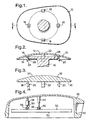
- FIGS 1 and 2 show a reflective member 10 for a vehicle mirror which is moulded from plastics material and has a reflective coating on its front convex surface 12.
- the reflective member 10 is parallel-sided, having a concave rear surface 14, from which four integrally moulded lugs 16, 18, 20 and 22, each of which has a ramp face 24 leading to a detent edge 26.
- the four lugs 16-22 are spaced apart with their ramps 24 and detents 26 facing inwardly so as to be a snap fit over a circular disk 28 formed on an end of a support pillar 30 which projects within a mirror case (not shown).
- Figure 3 illustrates another reflective member 32 having a convex surface 34 carrying a reflective coating similar to the surface 12 of Figures 1 and 2.
- the rear surface 36 of the reflective 32 is flat, with the result that the reflective member 32 is of non-uniform thickness.
- Integral lugs 16-22 similar to the correspondingly referenced lugs of Figures 1 and 2 project from the surface 36.
- the radius of curvature of the convex surfaces 12 and 34 would, in practice, be about two metres; the curvature has been exaggerated in Figures 2 and 3.
- Figure 4 shows a vehicle exterior mirror having a housing 40 with an end 42 adapted for connection to means (not shown) for mounting the mirror on a motor vehicle body.
- a support pillar 44 projects from the interior of the housing 40 and has a spherical formation 46 on its outer end which engages in a socket formation 48 which is integrally moulded onto the back of a plastics reflective member 50 which has a reflective coating on its front surface 52.
- the reflective member 50 has a second integrally moulded socket formation 54 which engages with a spherical formation 56 of a screw jack drive unit 58, which may, for example, be as described in EP-A-0272047, and which includes an electric motor to enable the reflective member 50 to be pivoted relative to the housing 40 about an axis through the spherical formation 46 perpendicular to the plane of the drawing.
- a similar screw jack drive unit (not shown) has its jacking screw engaging with a third spherical socket (not shown) which is integrally moulded with the reflective member 50 to permit adjustment about an axis through the spherical formation 46 orthogonal to the first mentioned axis.
- Figures 5 and 6 show the reflective member for a rear view mirror having a main zone which is flat or has a relatively large radius of curvature for providing the principal field of view, together with a side zone of smaller radius of curvature for providing an extended field of view to one side of the main field of view. With this type of mirror, it is acceptable for the quality of the image in the extended field of view to be less than that in the main field of view.
- the reflective member of Figures 5 and 6 consists of a glass mirror 60 which is secured in recess in a plastics member 62 which has a convex side zone 64 of smaller radius of curvature than the glass mirror 60 and which carries a reflective coating on its surface. Projecting from the rear surface of the member 62 are four lugs 16-22, similar to the correspondingly parts of Figures 1 and 2. Alternatively, the member 62 may be provided with spherical sockets similar to the sockets 46 and 54 of Figure 4.
- the reflective coating on the plastics member may be a chromium coating.
- a heater may be provided on the rear surface of the plastics member.
Landscapes
- Engineering & Computer Science (AREA)
- Multimedia (AREA)
- Mechanical Engineering (AREA)
- Rear-View Mirror Devices That Are Mounted On The Exterior Of The Vehicle (AREA)
- Optical Elements Other Than Lenses (AREA)
Description
- This invention relates to a vehicle mirror of the type comprising a housing, a reflective member, mounting means provided on the inside of the housing and means for attaching the rear surface of the reflective member to the mounting means.
- EP-A-0567245 discloses a mirror of this type in which the reflective member comprises a mirror glass which is secured by adhesive to a backing plate moulded from plastics material. The backing plate has formations which interlock with complementary formations on the mounting means. It is an object of the present invention to provide a rear view mirror of the type described above in which a separate backing plate is not necessary.
- According to the invention, in a vehicle mirror of the type described above, the reflective member is moulded from plastics material and has a reflective coating on at least part of its front surface and formations on its rear surface adapted to interlock with complementary formations on the mounting means.
- The mounting means may comprise means for varying the orientation of the reflective member relative to the housing.
- The invention is particularly applicable to vehicle mirrors with aspheric reflective members. The front surface of the reflective member has a main zone providing the legally required field of view, together with a zone of higher curvature which is used to eliminate the well known "blind spot" beside the vehicle and immediately behind the driver, as described in US-A-4331382. According to the invention, the reflective coating is confined to the. zone of higher curvature and a silvered glass reflective member is moulded into the plastics reflective member to provide the normal zone.
- One embodiment of the invention will now be described with reference to the accompanying drawings, in which:
- Figure 1 is an elevation from the rear of a reflective member showing the mounting means behind the reflective member partially broken away;
- Figure 2 is a cross-sectional view taken on the line 2-2 in Figure 1;
- Figure 3 is a cross-sectional view similar to Figure 2 of a modified reflective member;
- Figure 4 is a cross-sectional view of a rear view mirror having means for adjusting the orientation of the reflective member relative to the mirror case;
- Figure 5 is a front view of a rear view mirror in accordance with the present invention; and
- Figure 6 is a cross-sectional view on the line 6-6 in Figure 5.
-
- Figures 1 and 2 show a
reflective member 10 for a vehicle mirror which is moulded from plastics material and has a reflective coating on its frontconvex surface 12. Thereflective member 10 is parallel-sided, having a concaverear surface 14, from which four integrally mouldedlugs ramp face 24 leading to adetent edge 26. The four lugs 16-22 are spaced apart with theirramps 24 anddetents 26 facing inwardly so as to be a snap fit over acircular disk 28 formed on an end of asupport pillar 30 which projects within a mirror case (not shown). - Figure 3 illustrates another
reflective member 32 having aconvex surface 34 carrying a reflective coating similar to thesurface 12 of Figures 1 and 2. However, therear surface 36 of the reflective 32 is flat, with the result that thereflective member 32 is of non-uniform thickness. Integral lugs 16-22, similar to the correspondingly referenced lugs of Figures 1 and 2 project from thesurface 36. - It should be appreciated that, the radius of curvature of the
convex surfaces - Figure 4 shows a vehicle exterior mirror having a
housing 40 with anend 42 adapted for connection to means (not shown) for mounting the mirror on a motor vehicle body. A support pillar 44 projects from the interior of thehousing 40 and has aspherical formation 46 on its outer end which engages in asocket formation 48 which is integrally moulded onto the back of a plasticsreflective member 50 which has a reflective coating on itsfront surface 52. - The
reflective member 50 has a second integrally mouldedsocket formation 54 which engages with aspherical formation 56 of a screwjack drive unit 58, which may, for example, be as described in EP-A-0272047, and which includes an electric motor to enable thereflective member 50 to be pivoted relative to thehousing 40 about an axis through thespherical formation 46 perpendicular to the plane of the drawing. A similar screw jack drive unit (not shown) has its jacking screw engaging with a third spherical socket (not shown) which is integrally moulded with thereflective member 50 to permit adjustment about an axis through thespherical formation 46 orthogonal to the first mentioned axis. - Figures 5 and 6 show the reflective member for a rear view mirror having a main zone which is flat or has a relatively large radius of curvature for providing the principal field of view, together with a side zone of smaller radius of curvature for providing an extended field of view to one side of the main field of view. With this type of mirror, it is acceptable for the quality of the image in the extended field of view to be less than that in the main field of view. The reflective member of Figures 5 and 6 consists of a
glass mirror 60 which is secured in recess in aplastics member 62 which has aconvex side zone 64 of smaller radius of curvature than theglass mirror 60 and which carries a reflective coating on its surface. Projecting from the rear surface of themember 62 are four lugs 16-22, similar to the correspondingly parts of Figures 1 and 2. Alternatively, themember 62 may be provided with spherical sockets similar to thesockets - The reflective coating on the plastics member may be a chromium coating. A heater may be provided on the rear surface of the plastics member.
Claims (3)
- A vehicle mirror comprising a housing (40), a reflective member (62), mounting means (30; 46, 56) provided on the inside of the housing (40) and means for attaching the rear surface of the reflective member (62) to the mounting means (30; 46, 56), characterised in that the reflective member (62) is moulded from plastics material and has a reflective coating (12) on at least part of its front surface and formations (16-22; 48, 54) on its rear surface adapted to interlock with complementary formations (28; 46, 56) on the mounting means (30; 46, 56); said reflective member (62) having a main zone (60) providing a first field of view comprising a silvered glass reflective member (60) moulded into the plastics reflective member (62) and a zone (64) of higher curvature having said reflective coating (12).
- A vehicle mirror according to claim 1, wherein the mounting means (46, 56) comprises means for varying the orientation of the reflective member (62) relative to the housing (40).
- A vehicle mirror according to claim 1 or 2, wherein the reflective member (62) is aspheric.
Applications Claiming Priority (2)
| Application Number | Priority Date | Filing Date | Title |
|---|---|---|---|
| GB9705441 | 1997-03-15 | ||
| GBGB9705441.5A GB9705441D0 (en) | 1997-03-15 | 1997-03-15 | Vehicle rear view mirror |
Publications (3)
| Publication Number | Publication Date |
|---|---|
| EP0864465A2 EP0864465A2 (en) | 1998-09-16 |
| EP0864465A3 EP0864465A3 (en) | 1999-03-31 |
| EP0864465B1 true EP0864465B1 (en) | 2002-09-04 |
Family
ID=10809330
Family Applications (1)
| Application Number | Title | Priority Date | Filing Date |
|---|---|---|---|
| EP19980301520 Expired - Lifetime EP0864465B1 (en) | 1997-03-15 | 1998-03-02 | Vehicle rear view mirror |
Country Status (3)
| Country | Link |
|---|---|
| EP (1) | EP0864465B1 (en) |
| DE (1) | DE69807547T2 (en) |
| GB (1) | GB9705441D0 (en) |
Cited By (1)
| Publication number | Priority date | Publication date | Assignee | Title |
|---|---|---|---|---|
| CN102476608A (en) * | 2010-11-29 | 2012-05-30 | Smr专利责任有限公司 | plastic glass mounting and retaining device |
Families Citing this family (7)
| Publication number | Priority date | Publication date | Assignee | Title |
|---|---|---|---|---|
| FR2771352B1 (en) * | 1997-11-24 | 2000-01-14 | Magneti Marelli France | MIRROR HOLDER HAVING A DIVERGENT REFLECTIVE AREA |
| GB9820619D0 (en) | 1998-09-23 | 1998-11-18 | Britax Geco Sa | Temperature indicator for motor vehicle |
| DE102004050725B4 (en) * | 2004-10-19 | 2017-04-20 | manroland sheetfed GmbH | Method for transporting sheet material and processing machine thereto |
| DE102009016067A1 (en) | 2009-03-17 | 2010-09-23 | Steinemann Technology Ag | Device for conveying a bow |
| EP2821284B1 (en) | 2013-07-04 | 2018-03-07 | Fico Mirrors S.A. | Rear view mirror assembly for motor vehicles |
| CN105329355A (en) * | 2015-10-28 | 2016-02-17 | 无锡尊宝电动车有限公司 | Breakage-proof electric bicycle rearview mirror with double surfaces |
| DE102020205447A1 (en) | 2020-04-29 | 2021-11-04 | Volkswagen Aktiengesellschaft | Rearview mirror for a vehicle and vehicle with one |
Family Cites Families (4)
| Publication number | Priority date | Publication date | Assignee | Title |
|---|---|---|---|---|
| US4331382A (en) * | 1980-03-13 | 1982-05-25 | Pathfinder Auto Lamp Company | Wide-angle mirror for automobiles and the like |
| JPS6044316A (en) * | 1983-08-23 | 1985-03-09 | Kanto Seiki Kk | Molded mirror of resin and manufacture thereof |
| GB9208831D0 (en) * | 1992-04-23 | 1992-06-10 | Britax Wingard Ltd | Exterior rear view mirror for a motor vehicle |
| CH689183A5 (en) * | 1994-08-08 | 1998-11-30 | Weidmann H Ag | Rueckblickspiegel for motor vehicles. |
-
1997
- 1997-03-15 GB GBGB9705441.5A patent/GB9705441D0/en active Pending
-
1998
- 1998-03-02 DE DE1998607547 patent/DE69807547T2/en not_active Expired - Fee Related
- 1998-03-02 EP EP19980301520 patent/EP0864465B1/en not_active Expired - Lifetime
Cited By (2)
| Publication number | Priority date | Publication date | Assignee | Title |
|---|---|---|---|---|
| CN102476608A (en) * | 2010-11-29 | 2012-05-30 | Smr专利责任有限公司 | plastic glass mounting and retaining device |
| CN102476608B (en) * | 2010-11-29 | 2014-09-24 | Smr专利责任有限公司 | Plastic glass mounting and retention device |
Also Published As
| Publication number | Publication date |
|---|---|
| DE69807547D1 (en) | 2002-10-10 |
| EP0864465A2 (en) | 1998-09-16 |
| DE69807547T2 (en) | 2003-02-27 |
| GB9705441D0 (en) | 1997-04-30 |
| EP0864465A3 (en) | 1999-03-31 |
Similar Documents
| Publication | Publication Date | Title |
|---|---|---|
| EP0654379B1 (en) | Vehicle rearview mirror | |
| US4331382A (en) | Wide-angle mirror for automobiles and the like | |
| US10086765B2 (en) | Method for manufacturing a blind spot indicator for a vehicular exterior rearview mirror assembly | |
| US4268120A (en) | Automobile mirror device | |
| JP6689964B2 (en) | Toggle mechanism for rearview mirror assembly | |
| US4526446A (en) | Adjustable auxiliary rear-view mirror | |
| US11485289B2 (en) | Vehicular rearview mirror assembly | |
| US20120263450A1 (en) | Camera device with reduced size | |
| US20110194203A1 (en) | Exterior mirror assembly with actuator | |
| AU6587798A (en) | Electrochromic rearview mirror incorporating a third surface metal reflector | |
| EP0864465B1 (en) | Vehicle rear view mirror | |
| US7025469B1 (en) | Vehicle rear-view mirror with wide viewing angle and reduced image distortion | |
| US5838505A (en) | Divided-reflection method of wide-angle observation and wide-angle view automobile mirror | |
| JP2023524260A (en) | Rear vision device with actuator and vehicle with same | |
| US8425061B2 (en) | Exterior rearview mirror for motor vehicles | |
| WO2007040625A1 (en) | High definition vehicular mirror | |
| US20240286549A1 (en) | Interior rearview mirror assembly with pivot mount | |
| US6523965B1 (en) | Driver rearview mirror | |
| EP1743803B1 (en) | Mirror | |
| CN116946018A (en) | Exterior rearview mirrors and rearview mirror sets for vehicles | |
| WO1998055342A1 (en) | Exterior door mirror unit which can be installed on a vehicle | |
| US6206526B1 (en) | Bi-focal plane rear view mirror | |
| WO2022021204A1 (en) | Vehicular part and vehicle | |
| CN218327402U (en) | Angle-adjustable rearview camera | |
| US6450653B1 (en) | Tri-faceted vehicle side view mirror assembly |
Legal Events
| Date | Code | Title | Description |
|---|---|---|---|
| PUAI | Public reference made under article 153(3) epc to a published international application that has entered the european phase |
Free format text: ORIGINAL CODE: 0009012 |
|
| AK | Designated contracting states |
Kind code of ref document: A2 Designated state(s): DE FR GB |
|
| AX | Request for extension of the european patent |
Free format text: AL;LT;LV;MK;RO;SI |
|
| PUAL | Search report despatched |
Free format text: ORIGINAL CODE: 0009013 |
|
| AK | Designated contracting states |
Kind code of ref document: A3 Designated state(s): AT BE CH DE DK ES FI FR GB GR IE IT LI LU MC NL PT SE |
|
| AX | Request for extension of the european patent |
Free format text: AL;LT;LV;MK;RO;SI |
|
| 17P | Request for examination filed |
Effective date: 19990526 |
|
| AKX | Designation fees paid |
Free format text: DE FR GB |
|
| 17Q | First examination report despatched |
Effective date: 20010427 |
|
| GRAG | Despatch of communication of intention to grant |
Free format text: ORIGINAL CODE: EPIDOS AGRA |
|
| GRAG | Despatch of communication of intention to grant |
Free format text: ORIGINAL CODE: EPIDOS AGRA |
|
| GRAH | Despatch of communication of intention to grant a patent |
Free format text: ORIGINAL CODE: EPIDOS IGRA |
|
| GRAG | Despatch of communication of intention to grant |
Free format text: ORIGINAL CODE: EPIDOS AGRA |
|
| GRAH | Despatch of communication of intention to grant a patent |
Free format text: ORIGINAL CODE: EPIDOS IGRA |
|
| GRAH | Despatch of communication of intention to grant a patent |
Free format text: ORIGINAL CODE: EPIDOS IGRA |
|
| GRAA | (expected) grant |
Free format text: ORIGINAL CODE: 0009210 |
|
| AK | Designated contracting states |
Kind code of ref document: B1 Designated state(s): DE FR GB |
|
| REG | Reference to a national code |
Ref country code: GB Ref legal event code: FG4D |
|
| REF | Corresponds to: |
Ref document number: 69807547 Country of ref document: DE Date of ref document: 20021010 |
|
| PG25 | Lapsed in a contracting state [announced via postgrant information from national office to epo] |
Ref country code: GB Free format text: LAPSE BECAUSE OF NON-PAYMENT OF DUE FEES Effective date: 20030302 |
|
| ET | Fr: translation filed | ||
| PLBE | No opposition filed within time limit |
Free format text: ORIGINAL CODE: 0009261 |
|
| STAA | Information on the status of an ep patent application or granted ep patent |
Free format text: STATUS: NO OPPOSITION FILED WITHIN TIME LIMIT |
|
| 26N | No opposition filed |
Effective date: 20030605 |
|
| GBPC | Gb: european patent ceased through non-payment of renewal fee | ||
| REG | Reference to a national code |
Ref country code: FR Ref legal event code: CD |
|
| PGFP | Annual fee paid to national office [announced via postgrant information from national office to epo] |
Ref country code: FR Payment date: 20080314 Year of fee payment: 11 Ref country code: DE Payment date: 20080321 Year of fee payment: 11 |
|
| REG | Reference to a national code |
Ref country code: FR Ref legal event code: ST Effective date: 20091130 |
|
| PG25 | Lapsed in a contracting state [announced via postgrant information from national office to epo] |
Ref country code: DE Free format text: LAPSE BECAUSE OF NON-PAYMENT OF DUE FEES Effective date: 20091001 |
|
| PG25 | Lapsed in a contracting state [announced via postgrant information from national office to epo] |
Ref country code: FR Free format text: LAPSE BECAUSE OF NON-PAYMENT OF DUE FEES Effective date: 20091123 |