EP0863529A1 - Electromagnetic relay - Google Patents
Electromagnetic relay Download PDFInfo
- Publication number
- EP0863529A1 EP0863529A1 EP98104052A EP98104052A EP0863529A1 EP 0863529 A1 EP0863529 A1 EP 0863529A1 EP 98104052 A EP98104052 A EP 98104052A EP 98104052 A EP98104052 A EP 98104052A EP 0863529 A1 EP0863529 A1 EP 0863529A1
- Authority
- EP
- European Patent Office
- Prior art keywords
- movable
- block
- isolation
- base block
- electromagnetic relay
- Prior art date
- Legal status (The legal status is an assumption and is not a legal conclusion. Google has not performed a legal analysis and makes no representation as to the accuracy of the status listed.)
- Granted
Links
Images


Classifications
-
- H—ELECTRICITY
- H01—ELECTRIC ELEMENTS
- H01H—ELECTRIC SWITCHES; RELAYS; SELECTORS; EMERGENCY PROTECTIVE DEVICES
- H01H50/00—Details of electromagnetic relays
- H01H50/02—Bases; Casings; Covers
- H01H50/026—Details concerning isolation between driving and switching circuit
-
- H—ELECTRICITY
- H01—ELECTRIC ELEMENTS
- H01H—ELECTRIC SWITCHES; RELAYS; SELECTORS; EMERGENCY PROTECTIVE DEVICES
- H01H51/00—Electromagnetic relays
- H01H51/22—Polarised relays
- H01H51/2272—Polarised relays comprising rockable armature, rocking movement around central axis parallel to the main plane of the armature
- H01H51/2281—Contacts rigidly combined with armature
- H01H51/229—Blade-spring contacts alongside armature
Definitions
- This invention generally relates to electromagnetic relays and, more particularly, to a structure for providing electrical isolation in an electromagnetic relay.
- movable armature block 105 is supported by way of permanent magnet 104 on the upper surface of coil block 103 in a way that it is free to rotate.
- movable contact springs 152 are on either side of contact element 151. These contact springs 152 are formed integrally with crosspiece 153 from a composite resin material.
- contact element 151 is separated from movable contact springs 152 by a set of partitions 116 which come down from the ceiling of case 112. This is done to increase the isolation between contact element 151 and movable contact springs 152.
- a drawback of the above electromagnetic relay is that there can be spaces between the lower ends of partitions 116 and crosspiece 153, and spaces between the side ends of partitions 116 and the interior wall of case 112. This causes the isolation distance between the contact element 151 and movable contact springs 152 to be short, which results in poor isolation characteristics.
- there has been an increase in demand for smaller and smaller electromagnetic relays but the smaller the relay becomes, the poorer its isolation characteristics. Accordingly, there exists a need for a structure that provides adequate electrical isolation in electromagnetic relays.
- an objective of the invention is to provide an electromagnetic relay with excellent electrical isolation characteristics.
- the electromagnetic relay has an electromagnetic block, a base block where the electromagnetic block is fixed, and a movable block having a movable iron member and a movable contact member.
- the electromagnetic relay is characterized by a configuration where the base block further comprises an L-shaped wall protruded upwardly to have wider and longer electromagnetic isolation between the movable iron member and the movable contact member, resulting in good isolation characteristics.
- This invention is further characterized by a configuration where a cover has an isolation rib which comes to contact with the isolation walls for better isolation.
- Figure 1 is an exploded perspective drawing of an electromagnetic relay in a first ideal embodiment of this invention.
- Figure 2 is an exploded perspective drawing of the electromagnetic relay of Figure 1 as seen from below.
- Figure 3(a) shows a planar cross section of the electromagnetic relay of Figure 1 after assembly
- Figure 3(b) is a frontal cross section of the electromagnetic relay of Figure 1
- Figure 3(c) is a partial cross section of the electromagnetic relay of Figure 1 taken across line A-A of Figure 3(b).
- Figure 4 is a lateral cross section of the electromagnetic relay shown in Figure 3(a).
- Figure 5(a) is a perspective drawing of the core with the spool formed on it as viewed from above; and Figure 5(b) is a perspective drawing of the core with the spool formed on it as viewed from below.
- Figure 6(a) is a perspective drawing of the electromagnetic block as viewed from above; and Figure 6(b) is a perspective drawing of the electromagnetic block as viewed from below.
- Figure 7 is a perspective drawing showing the secondary molding process executed on the electromagnetic block.
- Figure 8(a) is a plan view showing how the electromagnetic block is molded in the secondary process; and Figures 8(b) and (c) are magnified plan views of key components of the electromagnetic block.
- Figure 9(a) is a lateral view showing how the electromagnetic block is molded in the secondary process; and Figure 9(b) is a frontal view showing how the electromagnetic block is molded in the secondary process.
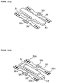
- Figure 10(a) is a perspective drawing of the movable block as seen from above before it is resin-molded.
- Figure 10(b) is a perspective drawing of the movable block as seen from below before it is resin-molded.
- Figure 11 is a perspective drawing of the electromagnetic relay when the movable block has been mounted to the base block.
- Figure 12(a) is a perspective drawing of another embodiment of the base block; and Figure 12(b) is a plan view of another embodiment of the base block.
- Figure 13 is a perspective drawing of the case, which has been turned upside down and partially cut away.
- Figure 14 shows a prior art electromagnetic relay.
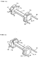
- An electromagnetic relay of this invention primarily comprises a base block 20 which is formed by performing a secondary molding process on an electromagnetic block 10, a movable block 30 and a case 40.
- the exterior dimensions of the electromagnetic relay of this embodiment are 10 mm x 5 mm x 5 mm.
- coil 16 is wrapped around core 11, which is shaped like a " ⁇ ".
- a primary molding process is applied on ⁇ -shaped core 11 to form spool 12.
- Flanges 13 and 14 are formed on either end of core 11 to form the spool. From either side of the flange 14 extend two connector elements 18.
- Coil 16 is wrapped around the center portion of the core 11.
- the wire which is drawn out is tied and soldered to post 17a on lug terminal strip 17, which is insert-molded onto flange 13 (see Figure 6).
- Base block 20 is formed by applying a secondary molding process on the electromagnetic block 10, which is connected to lead frame 50.
- Common terminals 21, fixed contact terminals 22 and 23 and coil terminals 24 are formed by cutting out portions of the lead frame 50.
- Support 51 is also formed this way.
- Fixed contacts 22a and 23a are mounted on the fixed contact terminals 22 and 23, respectively.
- Connecting terminals 17 on electromagnetic block 10 are welded to the free ends of coil terminal 24; and the connector elements 18 are welded to support 51 on lead frame 50. All these components are positioned properly in a mold and a secondary molding process is applied. Connector elements 18 are then cut away from the lead frame 50. Terminals 21 through 24 are formed by cutting and bending the frame, completing the formation of the base block 20. Finally, the base of each terminal 21 through 24 is made flush with the exterior surface of the base block 20.
- terminals 21 through 24 When terminals 21 through 24 are bent downward, they bend at this narrow portion.
- Terminals 21 through 24 fit into shallow grooves in base block 20, so their exterior surfaces are virtually flush with the surface of the base block 20.
- the distance from the side of base block 20 before the terminals are bent to narrow portions 21b through 24b should be between 0 and 0.05 mm.
- the base block 20 is produced by a secondary molding process, and has a shallow depressed area 25 on its upper surface.
- two small bosses, 26a and 26b are two small bosses, 26a and 26b.
- One of these bosses, 26a has a long top ridge line along its apex which will make linear contact with movable block 30, as will be discussed next.
- the other boss, 26b has a shorter top ridge line along its apex in order to absorb any variation in the accuracy of the width dimension.
- Poles 11a and 11b of core 11 are segregated from fixed contact terminals 22a and 23a by wall 27, which is shaped like an angular letter C when seen from above.
- the outer sides of the wall 27 which are opposite to the facing sides is tapered (see Figure 4).
- Connector elements 21a of common terminals 21 protrude from the corners formed in the middle of the cut-away side of the base block 20.
- projections 28 protrude further than connector elements 18, fixed contact terminals 23 and end portions 18a, 23c and 24c. This is to prevent end portions 23c and 24c from getting caught or hung up on each other when base blocks 20 are continuously conveyed.
- Base block 20 is not limited to that described above.
- Base block 20 could have a configuration of four separate L-shaped walls 27, as illustrated in Figure 12, for providing electrical isolation.
- Movable block 30, as illustrated in Figures 10(a) and 10(b), has movable contact elements 32 arrayed in parallel on either side of permanent magnet 31.
- Movable iron member 33 is laid atop one of the surfaces of the permanent magnet 31, and isolation platform 34 is formed of molded resin in a way that it is integral to the iron member (see Figure 11).
- the permanent magnet 31 is narrower than movable iron member 33 and is placed on the so-called "dull" side of member 33. Placing the permanent magnet 31 on the dull side of member 33 prevents any space between the magnet and the member which would impede proper contact between them on reset, a problem which might occur when member 33 is subject to the pressing process.
- the two may be resin-molded together.
- the two pieces may be temporarily anchored in any number of ways: they may be laser-welded; welded with a gas burner; spot-welded; or a thin metal film may be melted on the two surfaces to be joined.
- a variety of metals may be used for this film, including elemental nickel, zinc, cadmium, tin, copper, chrome, lead, silver, gold, palladium, or their alloys.
- the thin film may be formed by any of various methods known in the prior art, including plating, vapor deposition or slushing.
- the thin film may be applied to the entire surface to be joined, or only the edges or the center may be treated.
- the thin film may be melted by irradiating it with a laser, by heating it with a gas burner or by heating it via electrical resistance.
- Movable contact elements 32 are formed by stamping a thin plate of conductive spring material. The ends of each element are bifurcated along the axial line. Two movable contacts 32a are placed on one of the bifurcated ends, and two contacts 32b are placed on the opposite ends. In the center of each movable contact element 32 is a T-shaped connector 32c which extends out to the side.
- Movable block 30 may be formed in the following way. After movable contacts 32a and 32b have been attached, movable contact elements 32, which have been cut out of a lead frame (not shown) in a pressing process, are positioned in a mold. Permanent magnet 31 and movable iron member 33, temporarily anchored together, are also positioned in the mold. These components are then secured to isolation platform 34, formed of molded resin, in a way as to be integral to the platform.
- the gap between movable contact elements 32 and movable iron member 33 measures approximately 0.9 mm.
- movable block 30 When movable block 30 is positioned onto the base block 20 and bosses 26a and 26b on the upper surface of base block 20 engage in depressions 34a and 34b (see Figure 2) on the lower surface of isolation platform 34, the components are automatically locked into their proper positions.
- connectors 32c on the movable contact elements 32 are welded to portions 21a of common terminals 21, movable block 30 is supported in a way that it can rotate.
- bosses 26a and 26b on base block 20 engage in depressions 34a and 34b on the lower surface of isolation platform 34 to support movable block 30. If the distance between bosses 26a and 26b should vary due to processing tolerance, then this variation will be absorbed by the bosses themselves because boss 26b has a shorter ridge line than boss 26a. This feature prevents faulty operation of the relay caused by variations attributable to processing tolerance.
- bosses 26a and 26b were provided.
- the invention is not limited to this case, however.
- a single boss or more than two bosses could also be provided.
- shape of the bosses is not limited to that described above.
- Their tops could also be triangular, conical or hemispherical. It is acceptable that the tops of bosses 26a and 26b be acutely angled and the bottoms of depressions 34a and 34b be obtusely angled. This makes it unlikely for the rotational fulcrum to wobble.
- the angular C-shaped isolation walls 27 segregate movable iron members 33 from movable contact elements 32.
- the spatial distance between movable iron members 33 and movable contact elements 32 is approximately 9 mm. This configuration of placing the walls 27 between the movable iron members 33 and the movable contact elements 32 results in a longer creepage distance between the surfaces of the two components, thus resulting in good isolation characteristics.
- isolation platform 34 The end portions 34c and 34d of isolation platform 34 are extended so that they overlap isolation walls 27. This allows a longer creepage distance between the surfaces of the two components, further improving the isolation characteristics.
- case 40 is a box-like cover which engages with base block 20. Cut-away portions 41 along the open edge of the case serve to attach it to the base block. Case 40 also has a hole on the edge of its upper surface through which gas can be removed. Referring to Figure 13, a number of ribs 43 are provided on the ceiling of case 40. These ribs 43 project downward from the ceiling of case 40. A surface of each of the ribs 43 which comes in contact with one of outer isolation walls 27 on base block 20 is tapered.
- Case 40 is mounted to base block 20, to which movable block 30 has already been attached.
- the terminals 21 through 24 engage in cut-away portions 41.
- isolation ribs 43 on case 40 come up against the outer surfaces of isolation walls 27 on the base block 20. This increases the creepage distance between the surfaces of the two components and, therefore, improves the isolation characteristics.
- the edges of isolation walls 27 and ribs 43 which come into contact with each other are tapered so that they fit smoothly and are easy to assemble.
- Ribs 43 may also be located so as to come up against the inner surfaces of isolation walls 27.
- movable iron member 33 When an inverse voltage (to the above voltage) is applied to coil 16, movable iron member 33 will rotate in the direction opposite that described above, that is, against the magnetic force of permanent magnet 31; and movable contact element 32 will rotate with it. Movable contacts 32b will separate from fixed contacts 23a, and movable contacts 32a will come in contact with fixed contacts 22a. End 33a of movable iron member 33 will be attracted to pole 11a of core 11, and the relay will return to its original state.
- the embodiment of the electromagnetic relay discussed above is a locking type, the invention is by no means limited to this form only. It could as well be applied in a resetting type of electromagnetic relay.
- the electromagnetic device of this invention has four L-shaped walls for isolating the ends of the movable iron member. Also, the ends of the isolation platform on the movable block extend far enough to overlap the walls. This design provides an electromagnetic relay with a longer creepage distance than prior art relays and, as a result, provides better isolation characteristics.
- isolation ribs are provided on the ceiling of the case which meet the surfaces of the walls. There is thus no linear gap between the partitions and the ceiling of the case. The creepage distance is increased and the isolation characteristics are further improved.
- the contacting surfaces of either the partitions, the ribs or both are tapered. This prevents the ribs from getting hung up on the partitions when the case is assembled. As a result, the relay can be assembled more smoothly, and the assembly task is further simplified.
- the greater part of the movable iron member is coated with a resin material to boost isolation characteristics.
Abstract
Description
Claims (8)
- An electromagnetic relay, comprising:an electromagnetic block formed by winding a coil around a core whose cross section is shaped like a backward letter "C";a base block which is formed by applying a secondary molding process on said electromagnetic block so that two magnetic poles on ends of said core are exposed upwardly from said base block;a movable block having a movable iron member and a movable contact member arranged on at least one side of said movable iron member, wherein a central portion of said movable iron member and said movable contact member are formed integrally with an isolation platform of molded resin, both ends of said movable iron member are placed so as to be able to make or break contact with said two magnetic poles on said ends of said core, and said movable block is supported on an upper surface of said base block in a way that said movable block is free to rotate, and a contact on said movable contact elements is made or broken when said movable iron member rotates in response to an excitation of said electromagnetic block or a removal of said excitation,
wherein said base block further comprises an L-shaped wall protruding upward from said upper surface of said base block, and a side surface of said isolation platform of molded resin overlaps a side surface of said L-shaped wall. - An electromagnetic relay according to claim 1, further comprising a case having an isolation rib projected downward from a ceiling of said case, said isolation rib contacting said L-shaped wall.
- An electromagnetic relay according to claim 2, wherein a contacting surface of either said isolation rib or said L-shaped wall is tapered.
- An electromagnetic relay according to claim 1, wherein said movable block is coated with a resin material except a portion of said movable contacting member which comes in contact with said two magnetic poles on said ends of said core.
- An apparatus for providing electrical isolation in an electromagnetic relay, the electromagnetic relay including a base block, a movable block positioned on the base block having a movable iron member and a movable contact member, and a case mounted on the base block, said apparatus comprising:an isolation wall on the base block for isolating the movable iron member and the movable contact member; andan isolation platform on the movable block for integrally forming a central portion of the movable iron member and the movable contact member and for overlapping a surface of the isolation wall.
- The apparatus of claim 5, wherein the isolation wall is an L-shaped wall.
- The apparatus of claim 6, wherein the isolation wall is an angular C-shaped wall.
- The apparatus of claim 6, further comprising an isolation rib in the case, said isolation rib contacting said isolation wall.
Applications Claiming Priority (3)
| Application Number | Priority Date | Filing Date | Title |
|---|---|---|---|
| JP5308297 | 1997-03-07 | ||
| JP53082/97 | 1997-03-07 | ||
| JP5308297 | 1997-03-07 |
Publications (2)
| Publication Number | Publication Date |
|---|---|
| EP0863529A1 true EP0863529A1 (en) | 1998-09-09 |
| EP0863529B1 EP0863529B1 (en) | 2002-10-30 |
Family
ID=12932880
Family Applications (1)
| Application Number | Title | Priority Date | Filing Date |
|---|---|---|---|
| EP98104052A Expired - Lifetime EP0863529B1 (en) | 1997-03-07 | 1998-03-06 | Electromagnetic relay |
Country Status (5)
| Country | Link |
|---|---|
| US (1) | US6107903A (en) |
| EP (1) | EP0863529B1 (en) |
| CN (1) | CN1108619C (en) |
| DE (1) | DE69808978T2 (en) |
| ES (1) | ES2184156T3 (en) |
Cited By (1)
| Publication number | Priority date | Publication date | Assignee | Title |
|---|---|---|---|---|
| WO2011131167A3 (en) * | 2010-04-21 | 2011-12-29 | Johnson Electric Dresden Gmbh | Bistable magnetic actuator |
Families Citing this family (11)
| Publication number | Priority date | Publication date | Assignee | Title |
|---|---|---|---|---|
| JP2003242873A (en) * | 2002-02-19 | 2003-08-29 | Fujitsu Component Ltd | Micro-relay |
| JP4466506B2 (en) * | 2005-08-12 | 2010-05-26 | オムロン株式会社 | relay |
| JP4888211B2 (en) * | 2007-04-25 | 2012-02-29 | オムロン株式会社 | Electromagnetic relay |
| JP2010044974A (en) * | 2008-08-15 | 2010-02-25 | Fujitsu Component Ltd | Electromagnetic relay |
| TW201029037A (en) * | 2009-01-21 | 2010-08-01 | Good Sky Electric Co Ltd | Electromagnetic relay and assembling method of its electromagnet unit |
| WO2013033722A1 (en) * | 2011-09-02 | 2013-03-07 | Cavendish Kinetics, Inc | Merged legs and semi-flexible anchoring for mems device |
| DE102012006438A1 (en) | 2012-03-30 | 2013-10-02 | Phoenix Contact Gmbh & Co. Kg | Relay with two counter-operable switches |
| DE102012006432B4 (en) | 2012-03-30 | 2013-10-31 | Phoenix Contact Gmbh & Co. Kg | Electromagnetic relay with improved insulation properties |
| DE102012006433B4 (en) | 2012-03-30 | 2014-01-02 | Phoenix Contact Gmbh & Co. Kg | Relay with improved insulation properties |
| US11962214B2 (en) * | 2019-05-28 | 2024-04-16 | B&R Industrial Automation GmbH | Transport device |
| CN113798622A (en) * | 2020-06-11 | 2021-12-17 | 贵州振华群英电器有限公司(国营第八九一厂) | Laser brazing method, brazing system and clamp for contact part of electromagnetic relay |
Citations (4)
| Publication number | Priority date | Publication date | Assignee | Title |
|---|---|---|---|---|
| EP0192928A1 (en) * | 1985-02-12 | 1986-09-03 | Siemens Aktiengesellschaft | Electromagnetic relay |
| EP0197391A2 (en) * | 1985-03-25 | 1986-10-15 | EURO-Matsushita Electric Works Aktiengesellschaft | Polarized electromagnetic relay |
| DE3935351A1 (en) * | 1989-10-24 | 1991-04-25 | Standard Elektrik Lorenz Ag | Contact system for miniature electrical relay - has fixed contacts on plates locating on conductor pins |
| EP0727803A1 (en) * | 1992-11-25 | 1996-08-21 | Matsushita Electric Works Ltd | Polarized relay |
Family Cites Families (4)
| Publication number | Priority date | Publication date | Assignee | Title |
|---|---|---|---|---|
| US4975666A (en) * | 1989-03-28 | 1990-12-04 | Matsushita Electric Works, Ltd. | Polarized electromagnetic relay |
| JPH05274984A (en) * | 1992-03-27 | 1993-10-22 | Omron Corp | Electromagnetic relay |
| JPH07245052A (en) * | 1994-03-04 | 1995-09-19 | Omron Corp | Electromagnet device |
| CN1034977C (en) * | 1994-04-22 | 1997-05-21 | 永本光树 | Polarized relay with rotative supporting point |
-
1998
- 1998-03-03 CN CN98105420A patent/CN1108619C/en not_active Expired - Lifetime
- 1998-03-06 ES ES98104052T patent/ES2184156T3/en not_active Expired - Lifetime
- 1998-03-06 DE DE69808978T patent/DE69808978T2/en not_active Expired - Lifetime
- 1998-03-06 US US09/036,384 patent/US6107903A/en not_active Expired - Lifetime
- 1998-03-06 EP EP98104052A patent/EP0863529B1/en not_active Expired - Lifetime
Patent Citations (4)
| Publication number | Priority date | Publication date | Assignee | Title |
|---|---|---|---|---|
| EP0192928A1 (en) * | 1985-02-12 | 1986-09-03 | Siemens Aktiengesellschaft | Electromagnetic relay |
| EP0197391A2 (en) * | 1985-03-25 | 1986-10-15 | EURO-Matsushita Electric Works Aktiengesellschaft | Polarized electromagnetic relay |
| DE3935351A1 (en) * | 1989-10-24 | 1991-04-25 | Standard Elektrik Lorenz Ag | Contact system for miniature electrical relay - has fixed contacts on plates locating on conductor pins |
| EP0727803A1 (en) * | 1992-11-25 | 1996-08-21 | Matsushita Electric Works Ltd | Polarized relay |
Cited By (2)
| Publication number | Priority date | Publication date | Assignee | Title |
|---|---|---|---|---|
| WO2011131167A3 (en) * | 2010-04-21 | 2011-12-29 | Johnson Electric Dresden Gmbh | Bistable magnetic actuator |
| US8461951B2 (en) | 2010-04-21 | 2013-06-11 | Johnson Electric Dresden Gmbh | Bistable magnetic actuators |
Also Published As
| Publication number | Publication date |
|---|---|
| US6107903A (en) | 2000-08-22 |
| DE69808978T2 (en) | 2003-06-18 |
| EP0863529B1 (en) | 2002-10-30 |
| ES2184156T3 (en) | 2003-04-01 |
| CN1108619C (en) | 2003-05-14 |
| DE69808978D1 (en) | 2002-12-05 |
| CN1193177A (en) | 1998-09-16 |
Similar Documents
| Publication | Publication Date | Title |
|---|---|---|
| WO2007132773A1 (en) | Electromagnetic relay | |
| WO2007132772A1 (en) | Electromagnetic relay | |
| EP0902452B1 (en) | Electromagnetic relay, joining structure for hinge spring and yoke in the electromagnetic relay | |
| US6107903A (en) | Electromagnetic relay | |
| EP1592036B1 (en) | Electromagnetic relay | |
| JP5004243B2 (en) | Electromagnetic relay | |
| US3878489A (en) | Electromagnetic relay having a printed circuit board connection between the contacts and radio type plug-in connector | |
| US4578660A (en) | Housing for an electromagnetic relay | |
| US3406361A (en) | Electromagnetic relay having parts retained by a one-piece spring clip which also provides armature bias | |
| JP3829392B2 (en) | Electromagnetic relay | |
| US5892423A (en) | Electric switching device and method of making a magnetic angle piece for same | |
| JPH09213189A (en) | Structure for electromagnetic relay | |
| JP3972448B2 (en) | Electromagnetic relay | |
| CN115910692A (en) | Electromagnetic relay | |
| JPS5816605B2 (en) | electromagnet device | |
| JP3454071B2 (en) | Electromagnet device | |
| JPH10255635A (en) | Electromagnetic microrelay | |
| JPH06267392A (en) | Electromagnetic relay | |
| JP2773236B2 (en) | Electromagnetic relay | |
| JP3666096B2 (en) | Electromagnetic relay and manufacturing method thereof | |
| JPH11354001A (en) | Electromagnetic relay | |
| JPH11329198A (en) | Contact mechanism | |
| JPH10256033A (en) | Electronic part | |
| JPS6346938B2 (en) | ||
| JP4091012B2 (en) | Circuit breaker |
Legal Events
| Date | Code | Title | Description |
|---|---|---|---|
| PUAI | Public reference made under article 153(3) epc to a published international application that has entered the european phase |
Free format text: ORIGINAL CODE: 0009012 |
|
| 17P | Request for examination filed |
Effective date: 19980403 |
|
| AK | Designated contracting states |
Kind code of ref document: A1 Designated state(s): DE ES FR GB IT |
|
| AX | Request for extension of the european patent |
Free format text: AL;LT;LV;MK;RO;SI |
|
| AKX | Designation fees paid |
Free format text: DE ES FR GB IT |
|
| RBV | Designated contracting states (corrected) |
Designated state(s): DE ES FR GB IT |
|
| 17Q | First examination report despatched |
Effective date: 20010330 |
|
| GRAG | Despatch of communication of intention to grant |
Free format text: ORIGINAL CODE: EPIDOS AGRA |
|
| GRAG | Despatch of communication of intention to grant |
Free format text: ORIGINAL CODE: EPIDOS AGRA |
|
| GRAH | Despatch of communication of intention to grant a patent |
Free format text: ORIGINAL CODE: EPIDOS IGRA |
|
| GRAH | Despatch of communication of intention to grant a patent |
Free format text: ORIGINAL CODE: EPIDOS IGRA |
|
| GRAA | (expected) grant |
Free format text: ORIGINAL CODE: 0009210 |
|
| AK | Designated contracting states |
Kind code of ref document: B1 Designated state(s): DE ES FR GB IT |
|
| REG | Reference to a national code |
Ref country code: GB Ref legal event code: FG4D |
|
| REF | Corresponds to: |
Ref document number: 69808978 Country of ref document: DE Date of ref document: 20021205 |
|
| REG | Reference to a national code |
Ref country code: ES Ref legal event code: FG2A Ref document number: 2184156 Country of ref document: ES Kind code of ref document: T3 |
|
| ET | Fr: translation filed | ||
| PLBE | No opposition filed within time limit |
Free format text: ORIGINAL CODE: 0009261 |
|
| STAA | Information on the status of an ep patent application or granted ep patent |
Free format text: STATUS: NO OPPOSITION FILED WITHIN TIME LIMIT |
|
| 26N | No opposition filed |
Effective date: 20030731 |
|
| PG25 | Lapsed in a contracting state [announced via postgrant information from national office to epo] |
Ref country code: IT Free format text: LAPSE BECAUSE OF NON-PAYMENT OF DUE FEES Effective date: 20050306 |
|
| PGRI | Patent reinstated in contracting state [announced from national office to epo] |
Ref country code: IT Effective date: 20091201 |
|
| REG | Reference to a national code |
Ref country code: DE Ref legal event code: R082 Ref document number: 69808978 Country of ref document: DE Representative=s name: KILIAN KILIAN & PARTNER MBB PATENTANWAELTE, DE Ref country code: DE Ref legal event code: R082 Ref document number: 69808978 Country of ref document: DE Representative=s name: KILIAN KILIAN & PARTNER, DE |
|
| REG | Reference to a national code |
Ref country code: FR Ref legal event code: PLFP Year of fee payment: 19 |
|
| REG | Reference to a national code |
Ref country code: FR Ref legal event code: PLFP Year of fee payment: 20 |
|
| PGFP | Annual fee paid to national office [announced via postgrant information from national office to epo] |
Ref country code: FR Payment date: 20170329 Year of fee payment: 20 |
|
| PGFP | Annual fee paid to national office [announced via postgrant information from national office to epo] |
Ref country code: GB Payment date: 20170329 Year of fee payment: 20 |
|
| PGFP | Annual fee paid to national office [announced via postgrant information from national office to epo] |
Ref country code: IT Payment date: 20170307 Year of fee payment: 20 |
|
| PGFP | Annual fee paid to national office [announced via postgrant information from national office to epo] |
Ref country code: DE Payment date: 20170329 Year of fee payment: 20 |
|
| PGFP | Annual fee paid to national office [announced via postgrant information from national office to epo] |
Ref country code: ES Payment date: 20170407 Year of fee payment: 20 |
|
| REG | Reference to a national code |
Ref country code: DE Ref legal event code: R071 Ref document number: 69808978 Country of ref document: DE |
|
| REG | Reference to a national code |
Ref country code: GB Ref legal event code: PE20 Expiry date: 20180305 |
|
| PG25 | Lapsed in a contracting state [announced via postgrant information from national office to epo] |
Ref country code: GB Free format text: LAPSE BECAUSE OF EXPIRATION OF PROTECTION Effective date: 20180305 |
|
| REG | Reference to a national code |
Ref country code: ES Ref legal event code: FD2A Effective date: 20200806 |
|
| PG25 | Lapsed in a contracting state [announced via postgrant information from national office to epo] |
Ref country code: ES Free format text: LAPSE BECAUSE OF EXPIRATION OF PROTECTION Effective date: 20180307 |