EP0863526A2 - Insulated type switchgear device - Google Patents
Insulated type switchgear device Download PDFInfo
- Publication number
- EP0863526A2 EP0863526A2 EP98102722A EP98102722A EP0863526A2 EP 0863526 A2 EP0863526 A2 EP 0863526A2 EP 98102722 A EP98102722 A EP 98102722A EP 98102722 A EP98102722 A EP 98102722A EP 0863526 A2 EP0863526 A2 EP 0863526A2
- Authority
- EP
- European Patent Office
- Prior art keywords
- arc
- movable
- electrode
- electrodes
- pair
- Prior art date
- Legal status (The legal status is an assumption and is not a legal conclusion. Google has not performed a legal analysis and makes no representation as to the accuracy of the status listed.)
- Granted
Links
Images


Classifications
-
- H—ELECTRICITY
- H01—ELECTRIC ELEMENTS
- H01H—ELECTRIC SWITCHES; RELAYS; SELECTORS; EMERGENCY PROTECTIVE DEVICES
- H01H33/00—High-tension or heavy-current switches with arc-extinguishing or arc-preventing means
- H01H33/60—Switches wherein the means for extinguishing or preventing the arc do not include separate means for obtaining or increasing flow of arc-extinguishing fluid
- H01H33/66—Vacuum switches
- H01H33/664—Contacts; Arc-extinguishing means, e.g. arcing rings
-
- H—ELECTRICITY
- H01—ELECTRIC ELEMENTS
- H01H—ELECTRIC SWITCHES; RELAYS; SELECTORS; EMERGENCY PROTECTIVE DEVICES
- H01H33/00—High-tension or heavy-current switches with arc-extinguishing or arc-preventing means
- H01H33/60—Switches wherein the means for extinguishing or preventing the arc do not include separate means for obtaining or increasing flow of arc-extinguishing fluid
- H01H33/66—Vacuum switches
- H01H33/666—Operating arrangements
- H01H2033/6668—Operating arrangements with a plurality of interruptible circuit paths in single vacuum chamber
-
- H—ELECTRICITY
- H01—ELECTRIC ELEMENTS
- H01H—ELECTRIC SWITCHES; RELAYS; SELECTORS; EMERGENCY PROTECTIVE DEVICES
- H01H31/00—Air-break switches for high tension without arc-extinguishing or arc-preventing means
- H01H31/003—Earthing switches
-
- H—ELECTRICITY
- H01—ELECTRIC ELEMENTS
- H01H—ELECTRIC SWITCHES; RELAYS; SELECTORS; EMERGENCY PROTECTIVE DEVICES
- H01H33/00—High-tension or heavy-current switches with arc-extinguishing or arc-preventing means
- H01H33/60—Switches wherein the means for extinguishing or preventing the arc do not include separate means for obtaining or increasing flow of arc-extinguishing fluid
- H01H33/66—Vacuum switches
- H01H33/662—Housings or protective screens
- H01H33/66207—Specific housing details, e.g. sealing, soldering or brazing
-
- H—ELECTRICITY
- H01—ELECTRIC ELEMENTS
- H01H—ELECTRIC SWITCHES; RELAYS; SELECTORS; EMERGENCY PROTECTIVE DEVICES
- H01H33/00—High-tension or heavy-current switches with arc-extinguishing or arc-preventing means
- H01H33/60—Switches wherein the means for extinguishing or preventing the arc do not include separate means for obtaining or increasing flow of arc-extinguishing fluid
- H01H33/66—Vacuum switches
- H01H33/666—Operating arrangements
- H01H33/6661—Combination with other type of switch, e.g. for load break switches
-
- H—ELECTRICITY
- H01—ELECTRIC ELEMENTS
- H01H—ELECTRIC SWITCHES; RELAYS; SELECTORS; EMERGENCY PROTECTIVE DEVICES
- H01H33/00—High-tension or heavy-current switches with arc-extinguishing or arc-preventing means
- H01H33/60—Switches wherein the means for extinguishing or preventing the arc do not include separate means for obtaining or increasing flow of arc-extinguishing fluid
- H01H33/66—Vacuum switches
- H01H33/666—Operating arrangements
- H01H33/6664—Operating arrangements with pivoting movable contact structure
Definitions
- the present invention relates to an improvement in an insulated type switchgear device, more specifically, an improvement in a vacuum type switchgear with multifunctions in which a pair of arc electrodes are designed to be separable through rotation of a movable conductor around a predetermined main axis.
- a commonly used transformer substation includes such as transformers, circuit breakers and disconnecting switches, and an electric power from the transformers is supplied via the circuit breakers and disconnecting switches to loads such as motors.
- loads such as motors.
- these circuit breakers as well as the disconnecting switches which are provided separately from these circuit breakers are opened, and further, by means of a grounding device remanent electric charges and inductive currents at a power source side are sinked into a ground so as to ensure safety of maintenance persons.
- switchgear devices for example, in a vacuum circuit breaker circuit making and breaking operations are performed by engaging and disengaging a pair of arc electrodes which are disposed in a vacuum tube.
- a vacuum circuit breaker having a structure, in which a movable conductor is moved with respect to a stationary conductor in vertical direction by means of an operating mechanism disposed outside the vacuum tube so as to engage and disengage the pair of arc electrodes, each provided at one end of the respective movable and stationary conductors, is frequently employed.
- a vacuum circuit breaker as disclosed, for example, in JP-A-55-143727(1980), in which a movable arc electrode is designed to engage and disengage with a stationary arc electrode through rotation of the movable arc electrode around a predetermined main axis, is also used.
- an arc is provided a driving force in a rotating direction by a current flowing through the arc electrodes and is always moved between the arc electrodes to thereby suppress the melting of metal on the surface of the arc electrodes.
- coil shaped electrodes provided at the back faces of the arc electrodes magnetic fluxes in axial direction of the arc electrodes are generated to thereby diffuse the arc uniformly between the arc electrodes and to reduce current density of the arc.
- conventional insulated type switchgear devices contain the following problems. Namely, in the conventional insulated type switchgear devices as disclosed, for example, in JP-A-3-273804(1991), circuit breakers, disconnecting switches and grounding switches therefor are separately manufactured and installed, therefore, the size of the device is increased. Further, with the circuit breaker making use of a rotating movement operation in which the engagement and disengagement with the stationary arc electrode is performed through rotation of the movable arc electrode around a predetermined axis, the pair of arc electrodes are placed in an offset position when performing a circuit breaking operation, therefore, a region which allows an arc ignition, in other words effective area of the arc electrodes decreases, thereby the circuit breaking performance thereof is likely reduced.
- the present invention is carried out in view of the above problems, and an object of the present invention is to provide an insulated type switchgear device as the similar types as explained above in which the offsetting of a pair of arc electrodes during the circuit breaking operation is suppressed to improve the circuit breaking performance thereof as well as the size thereof is reduced.
- an insulated type switchgear device in which a pair of arc electrodes are separably disposed in an opposing manner in a vacuum tube and a movable conductor extending from a back face of one of the arc electrodes, in that a movable arc electrode, to an outside from the vacuum tube and the pair of arc electrodes are designed to be separated through a rotation of the movable conductor around a predetermined main axis, wherein the movable arc electrode is structured in such a manner that an electrode center of the movable arc electrode when the movable arc electrode is brought into its circuit breaking position is to be located near a center axis of the stationary arc electrode, whereby the center of the movable arc electrode is offset from the center axis of the stationary arc electrode when the pair of arc electrodes are brought into their circuit making position.
- the pair of arc electrodes are structured in such a manner that an angle formed by the facing surfaces of the pair of arc electrodes when the movable arc electrode is brought into its circuit breaking position is designed to be less than 20°.
- the movable conductor is configurated in an L shape and a distance from the movable arc electrode to a bent portion of the L shaped movable conductor is selected to be longer than 30% of a diameter of the movable arc electrode.
- a grounding conductor is further disposed in the vacuum tube, and through the rotation of the movable conductor at least one of opening and closing between the pair of arc electrodes and between the movable conductor and the grounding conductor is effected.
- the stationary and movable arc electrodes are respectively provided with a ditch for magnetically driving an arc generated therebetween.
- one of the arc electrodes is disposed in advance in an offset relation with respect to the other arc electrode at their circuit making position, therefore, a possible offsetting of the pair of arc electrodes during a circuit breaking operation is reduced so that because of the reduced offsetting the circuit breaking performance thereof is improved.
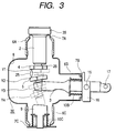
- Fig.1 shows a cross sectional view of the insulated type switchgear device.
- Numeral 30 is a vacuum tube and the vacuum tube 30 is disposed inside an insulation gas container 37. Namely, inside the insulation gas container 37 formed by molding epoxy resin the vacuum tube 30 is disposed, further, within the insulation gas container 37 insulation gas 1 such as SF6 gas is filled so that dielectric resistance along the outer surface of the vacuum tube 30 is improved.
- insulation gas 1 such as SF6 gas is filled so that dielectric resistance along the outer surface of the vacuum tube 30 is improved.
- the vacuum tube 30 is constituted in the following manner, in that above a metal casing 8 an insulator bushing 6A of ceramic material is provided, further a stationary conductor 2 is fixed via a seal metal fitting 7A provided above the insulator bushing 6A. Of course, the inside of the metal casing 8 is sealed in vacuum tight.
- a grounding conductor 9 is held by a seal metal fitting 7C via a bellows 10C.
- a movable conductor 3 which is disposed in perpendicular direction with respect to the stationary conductor 2 extends outside the vacuum tube 30 and is held by a bellows 10B and a seal metal fitting 7B.
- another insulator bushing 6B of ceramic material is provided at the side of the metal casing 8 at the side of the metal casing 8 insulator bushing 6B of ceramic material is provided.
- three insulator bushings 6A, 6B and 6C are provided, however, it is unnecessary to provide all of the three insulator bushings, in that it is sufficient if at least two insulator bushings are provided as in the embodiments 2 and 3 as illustrated in Figs.2 and 3.
- the stationary conductor 2 is connected to an inter connecting conductor 35 at the outside of the vacuum tube 30 and the inter connecting conductor 35 is secured to the insulation gas container 37.
- a bus side conductor 36A which is connected to a side portion of the inter connecting conductor 35 is connected to a bus 36B disposed in a bus insulator plate 36. Further, the bus side conductor 36A and the bus 36B are formed integrally with the bus insulator plate 36 by injection molding of epoxy resin.
- a stationary arc electrode 4 and a movable arc electrode 5 made of a material having a high melting point such as Cu-Pb alloy are respectively provided.
- spiral electrodes are used for the arc electrodes 4 and 5.
- spiral ditches 28 are respectively provided for the arc electrodes 4 and 5 and by means of a current flowing through the arc electrodes 4 and 5 the arc 25 is applied of a magnetic force directing in the circumference of the arc electrodes 4 and 5.
- the movable conductor 3 is designed to rotate around a main axis 15 provided at a connecting conductor 16.
- the movable conductor 3 is sandwiched by the connecting conductor 16 which is connected to a load side conductor 38 and is held by the main axis 15 which is inserted into respective through holes provided at the connecting conductor 16 and the movable conductor 3.
- the movable conductor 3 is coupled at an end portion 17 thereof to an operating mechanism portion 40 via an insulator rod 39.
- the movable conductor 3 is designed to be rotated via an operating device (not shown) around the main axis 15 in vertical direction and to be stopped at the following four positions. Namely, a circuit making position Y1 in which the movable arc electrode 5 is contacted with the stationary arc electrode 4 ; a circuit breaking position Y2 in which the movable arc electrode 5 is rotated downward from the circuit making position Y1 to interrupt a current flowing through the pair of arc electrodes 4 and 5 ; a disconnecting position Y3 in which the movable arc electrode 5 is further rotated downward to keep a dielectric distance which can withstand a high voltage caused by such as lightnings ; and a grounding position Y4 in which the movable arc electrode 5 is further rotated downward to contact with the grounding conductor 9.
- Fig.5 shows relationships between an offsetting L1 between the arc electrodes 4 and 5 at the time of circuit making position and circuit breaking performance and current carrying capacity of the arc electrodes 4 and 5.
- abscissa indicates the offsetting L1 normalized by the diameter of the arc electrodes 4 and 5.
- the offsetting L1 is preferable at least less than 20% of the diameter D of the arc electrodes 4 and 5 as indicated by a hatched region.
- Fig.6 shows relationships between an angle ⁇ formed by the arc electrodes 4 and 5 at the circuit breaking position Y2 and circuit breaking performance thereof, withstanding voltage between the arc electrodes 4 and 5 and durability of the bellows 10. As shown in Fig.6, the durability of the bellows 10 decreases depending on increase of the angle ⁇ , however, the withstanding voltage between the arc electrodes 4 and 5 increases because of increasing of the distance between the arc electrodes 4 and 5.
- the arc 25 tends to move toward a portion where arc length reduces to decrease arc resistance, therefore, when the angle ⁇ increases, an effective area, in other words a region where the arc 25 can passes through, decreases, thereby the circuit breaking performance of the arc electrodes 4 and 5 decreases.
- an effective area in other words a region where the arc 25 can passes through, decreases, thereby the circuit breaking performance of the arc electrodes 4 and 5 decreases.
- the movable conductor 3 is structured to be rotated around the main axis 15, a long stroke of the movable arc electrode 5 can be realized without imposing an undue burden on the bellows 10, and as a result, a long dielectric distance can be obtained, thereby the device according to the present embodiments can be used not only as circuit breakers but also as disconnecting switches.
- the present insulated type switchgear devices can be used as a single function switchgear such as a circuit breaker in which the movable arc electrode 5 is engaged and disengaged with the stationary arc electrode 4, a disconnecting switch in which the movable conductor 3 is moved from the stationary conductor 2 up to the disconnecting position Y3 and a grounding switch in which the movable conductor 3 and the grounding conductor 9 are used.
- the structure of the present insulated type switchgear device can also be employed without being disposed in the vacuum tube 30 or the insulation gas container 37.
- an embodiment 4 according to the present invention is explained.
- the stationary conductor 2 and the movable conductor 3 are arranged in an L shape, an electro-magnetic force acts on the arc 25 which causes to drive out the arc 25 toward the outside of the L shape (in left direction in Fig.1). Accordingly, the arc 25 can not be held between the arc electrodes 4 and 5 which possibly reduces the circuit breaking performance of the arc electrodes 4 and 5.
- the embodiment 4 is deviced for the purpose of reducing the above mentioned electro-magnetic force.
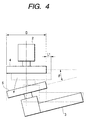
- Fig.7 shows a side cross sectional view of the embodiment 4.
- the movable conductor 3 is an L shaped conductor.
- the L shaped movable conductor 3 can be produced from an integral body, otherwise, as illustrated in Fig.7, the L shaped movable conductor 3 can be formed by, for example, soldering two pieces of straight line conductors 3a and 3b.
- an arc vapour shield 18 is provided around the arc electrodes 4 and 5 which is for preventing vapour metal particles from depositing on the inner wall of the insulator bushing 6A and from reducing the insulating property thereof.
- the arc electrodes 4 and 5 can be disposed in the metal casing 8 as in the embodiment 1 so as to eliminate the arc vapour shield 18.
- a current flowing through the movable conductor 3 causes an electro-magnetic force on the arc 25 directing to leftward in the drawing based on Fleming's rule and reduces a driving force acting on the arc 25 so as to move rightward.
- the arc 25 can be driven out from the arc electrodes 4 and 5 at a position A or can be confined inside the arc electrodes 4 and 5 at a position B because of a weak rotating force acting thereon. Accordingly, it is necessary to suppress an influence of the current flowing through the movable conductor 3 as much as possible.
- Electro-magnetic forces FA and FB acting on arc 25 at the positions A and B depend on a distance La from the movable arc electrode 5 to a bent portion of the movable conductor 3.
- Fig.9 shows such dependency.
- the abscissa indicates the distance La normalized by the diameter Ld of the arc electrodes 4 and 5 and, further, the ordinate indicates the electro-magnetic force acting on the arc 25 normalized by an electro-magnetic force induced by a conventional electrode arrangement shown in Fig.10.
- the current flowing through the movable conductor 3 exerts a large electro-magnetic force, in particular, to the arc 25 at the position B, however, depending on an increase of La the influence thereof is relaxed.
- the present embodiment 4 has the following advantages. Namely, through the determination of the distance La from the movable arc electrode 5 to the bent portion of the L shaped movable conductor 3 more than 30% of the diameter Ld of the arc electrodes 4 and 5 the influence of the current flowing through the movable conductor 3 affected on the arc 25 can be reduced. Accordingly, the behavior of the arc 25 is solely determined by the current flowing through the arc electrodes 4 and 5. Namely, the arc 25 behaves in the like manner as that in a conventional vacuum circuit breaker in which arc electrodes are moved in their axial direction, thereby the structure of the present embodiment can be applied to the conventional electrode structure.
- the circuit breaking performance of the arc electrodes is improved due to the advance offsetting, thereby the size of this sort of insulated type switchgear devices is reduced.
Abstract
Description
Claims (8)
- An insulated type switchgear device in which a pair of arc electrodes (4, 5) are separably disposed in an opposing manner in a vacuum tube (30) and a movable conductor (3) extending from a back face of one of the arc electrodes (4, 5), a movable arc electrode (5), to an outside from the vacuum tube (30) and the pair of arc electrodes (4, 5) are designed to be separated through a rotation of the movable conductor (3) around a predetermined main axis (15), characterized in that said movable arc electrode (5) is structured in such a manner that an electrode center of said movable arc electrode (5) when said movable arc electrode (5) is brought into its circuit breaking position (Y2) is to be located near a center axis of said stationary arc electrode (4).
- An insulated type switchgear device in which a pair of arc electrodes (4, 5) are separably disposed in an opposing manner in a vacuum tube (30) and a movable conductor (3) extending from a back face of one of the arc electrodes (4, 5), a movable arc electrode (5), to an outside from the vacuum tube (30) and the pair of arc electrodes (4, 5) are designed to be separated through a rotation of the movable conductor (3) around a predetermined main axis (15), characterized in that said movable arc electrode (5) is structured in such a manner that an electrode center of said movable arc electrode (5) when said movable arc electrode (5) is brought into its circuit breaking position (Y2) is to be located near a center axis of the stationary arc electrode (4), whereby the center of said movable arc electrode (5) is offset from the center axis of the stationary arc electrode (4) when said pair of arc electrodes (4, 5) are brought into their circuit making position (Y1).
- An insulated type switchgear device according to claim 2, wherein the offsetting of the center of said movable arc electrode (5) from the center axis of said stationary arc electrode (4) is designed to be less than 20% of a diameter of said movable arc electrode (5).
- An insulated type switchgear device in which a pair of arc electrodes (4, 5) are separably disposed in an opposing manner in a vacuum tube (30) and a movable conductor (3) extending from a back face of one of the arc electrodes (4, 5), a movable arc electrode (5), to an outside from the vacuum tube (30) and the pair of arc electrodes (4, 5) are designed to be separated through a rotation of the movable conductor (3) around a predetermined main axis (15), characterized in that said pair of arc electrodes (4, 5) are structured in such a manner that an angle () formed by the facing surfaces of said pair of arc electrodes (4, 5) when said movable arc electrode (5) is brought into its circuit breaking position (Y2) is designed to be less than 20°.
- An insulated type switchgear device in which a pair of arc electrodes (4, 5) are separably disposed in an opposing manner in a vacuum tube (30) and a movable conductor (3) extending from a back face of one of the arc electrodes (4, 5), a movable arc electrode (5), to an outside from the vacuum tube (30) and the pair of arc electrodes (4, 5) are designed to be separated through a rotation of the movable conductor (3) around a predetermined main axis (15), characterized in that said movable conductor (3) is configurated in an L shape and a distance (La) from said movable arc electrode (5) to a bent portion of said L shaped movable conductor (3) is selected to be longer than 30% of a diameter of said movable arc electrode (5).
- An insulated type switchgear device according to one of claims 1 through 5, wherein a grounding conductor (9) is further disposed in said vacuum tube (30), and through rotation of said movable conductor (3) at least one of opening and closing between said pair of arc electrodes (4, 5) and between said movable conductor (3) and said grounding conductor (9) is effected.
- An insulated type switchgear device according to one of claims 1 through 6, wherein said stationary and movable arc electrodes (4, 5) are respectively provided with a ditch for magnetically driving an arc (25) generated therebetween.
- An insulated type switchgear device in which a pair of arc electrodes (4, 5) are separably disposed in an opposing manner in a vacuum tube (30) and a movable conductor (3) extending from a back face of one of the arc electrodes (4, 5), a movable arc electrode (5), to an outside from the vacuum tube (30) and the pair of arc electrodes (4, 5) are designed to be separated through a rotation of the movable conductor (3) around a predetermined main axis (15), characterized in that said movable arc electrode (5) is structured in such a manner that an electrode center of said movable arc electrode (5) when said movable arc electrode (5) is brought into its circuit breaking position (Y2) is to be located near a center axis of the stationary arc electrode (4), as well as said pair of arc electrodes (4, 5) are structured in such a manner that an angle () formed by the facing surfaces of said pair of arc electrodes (4, 5) when said movable arc electrode (5) is brought into its circuit breaking position (Y2) is designed to be less than 20°.
Applications Claiming Priority (3)
| Application Number | Priority Date | Filing Date | Title |
|---|---|---|---|
| JP05170597A JP3431439B2 (en) | 1997-03-06 | 1997-03-06 | Insulated switchgear |
| JP5170597 | 1997-03-06 | ||
| JP51705/97 | 1997-03-06 |
Publications (3)
| Publication Number | Publication Date |
|---|---|
| EP0863526A2 true EP0863526A2 (en) | 1998-09-09 |
| EP0863526A3 EP0863526A3 (en) | 1999-03-17 |
| EP0863526B1 EP0863526B1 (en) | 2005-08-31 |
Family
ID=12894321
Family Applications (1)
| Application Number | Title | Priority Date | Filing Date |
|---|---|---|---|
| EP98102722A Expired - Lifetime EP0863526B1 (en) | 1997-03-06 | 1998-02-17 | Insulated type switchgear device |
Country Status (9)
| Country | Link |
|---|---|
| US (1) | US6005213A (en) |
| EP (1) | EP0863526B1 (en) |
| JP (1) | JP3431439B2 (en) |
| KR (1) | KR100474173B1 (en) |
| CN (3) | CN1188883C (en) |
| CA (1) | CA2231304C (en) |
| DE (1) | DE69831365T2 (en) |
| ID (1) | ID20357A (en) |
| TW (1) | TW364138B (en) |
Cited By (5)
| Publication number | Priority date | Publication date | Assignee | Title |
|---|---|---|---|---|
| EP1022761A2 (en) * | 1999-01-25 | 2000-07-26 | Hitachi, Ltd. | Vacuum switching apparatus |
| EP1045498A2 (en) * | 1999-04-12 | 2000-10-18 | Mitsubishi Denki Kabushiki Kaisha | Vacuum insulated switch gear |
| EP1119010A1 (en) * | 1998-10-02 | 2001-07-25 | Hitachi, Ltd. | Vacuum switch and vacuum switch gear using the vacuum switch |
| EP1124241A1 (en) * | 1998-10-02 | 2001-08-16 | Hitachi, Ltd. | Vacuum switch gear |
| WO2008006915A1 (en) * | 2006-07-13 | 2008-01-17 | Ormazabal Y Cia, S.A. | Modular encapsulated electrical device for power distribution networks |
Families Citing this family (7)
| Publication number | Priority date | Publication date | Assignee | Title |
|---|---|---|---|---|
| DE19802893A1 (en) * | 1998-01-21 | 1999-07-22 | Siemens Ag | Low-voltage (LV) vacuum circuit-breaker vacuum interrupter chamber with ring-shaped insulator |
| TWI228339B (en) * | 2002-11-06 | 2005-02-21 | Mitsubishi Electric Corp | Metal-enclosed switchgear |
| CN101409175B (en) * | 2008-01-14 | 2011-05-04 | 北京维益埃电气有限公司 | Combined high-voltage load switch and high-voltage switchgear thereof |
| EP2337052B1 (en) * | 2009-12-17 | 2017-02-22 | ABB Schweiz AG | A switching device and a switchgear |
| EP2693223B8 (en) * | 2012-08-03 | 2021-09-08 | ABB Schweiz AG | Voltage measurement device with an insulating body |
| EP3650627A1 (en) * | 2018-11-07 | 2020-05-13 | Inalfa Roof Systems Group B.V. | Method and device for accurate positioning of a moveably arranged panel |
| CN111710540B (en) * | 2020-06-30 | 2022-11-11 | 广东电网有限责任公司 | Integrative communication equipment of adapted electricity |
Citations (2)
| Publication number | Priority date | Publication date | Assignee | Title |
|---|---|---|---|---|
| US1835596A (en) * | 1928-06-23 | 1931-12-08 | Westinghouse Electric & Mfg Co | Vacuum circuit breaker |
| DE4103101A1 (en) * | 1990-03-22 | 1991-09-26 | Mitsubishi Electric Corp | Isolating switch for gas-insulated switchgear - has support for rotary location of switch blade and bearing for three=phase drive shaft and earth |
Family Cites Families (8)
| Publication number | Priority date | Publication date | Assignee | Title |
|---|---|---|---|---|
| US3591743A (en) * | 1968-11-13 | 1971-07-06 | Mc Graw Edison Co | Vacuum-type circuit interrupter with flexible, weld-breaking contact structure |
| JPS55143727A (en) * | 1979-04-24 | 1980-11-10 | Meidensha Electric Mfg Co Ltd | Vacuum interrupter |
| JPS564130U (en) * | 1979-06-21 | 1981-01-14 | ||
| DE3407088A1 (en) * | 1984-02-27 | 1985-08-29 | Siemens AG, 1000 Berlin und 8000 München | CONTACT ARRANGEMENT FOR VACUUM SWITCHES |
| JP2790892B2 (en) * | 1990-03-22 | 1998-08-27 | 三菱電機株式会社 | Gas insulated switchgear |
| JPH04363828A (en) * | 1991-06-11 | 1992-12-16 | Toshiba Corp | Vacuum valve |
| US5387772A (en) * | 1993-11-01 | 1995-02-07 | Cooper Industries, Inc. | Vacuum switch |
| TW389919B (en) * | 1995-09-27 | 2000-05-11 | Hitachi Ltd | Insulated type switching device |
-
1997
- 1997-03-06 JP JP05170597A patent/JP3431439B2/en not_active Expired - Lifetime
-
1998
- 1998-02-17 EP EP98102722A patent/EP0863526B1/en not_active Expired - Lifetime
- 1998-02-17 DE DE69831365T patent/DE69831365T2/en not_active Expired - Lifetime
- 1998-02-19 TW TW087102364A patent/TW364138B/en not_active IP Right Cessation
- 1998-02-24 US US09/028,640 patent/US6005213A/en not_active Expired - Lifetime
- 1998-03-02 ID IDP980308A patent/ID20357A/en unknown
- 1998-03-05 KR KR10-1998-0007198A patent/KR100474173B1/en not_active IP Right Cessation
- 1998-03-05 CN CN01135995.1A patent/CN1188883C/en not_active Expired - Fee Related
- 1998-03-05 CN CN98106036A patent/CN1084039C/en not_active Expired - Fee Related
- 1998-03-05 CA CA002231304A patent/CA2231304C/en not_active Expired - Fee Related
- 1998-03-05 CN CNB2004100588772A patent/CN1311493C/en not_active Expired - Fee Related
Patent Citations (2)
| Publication number | Priority date | Publication date | Assignee | Title |
|---|---|---|---|---|
| US1835596A (en) * | 1928-06-23 | 1931-12-08 | Westinghouse Electric & Mfg Co | Vacuum circuit breaker |
| DE4103101A1 (en) * | 1990-03-22 | 1991-09-26 | Mitsubishi Electric Corp | Isolating switch for gas-insulated switchgear - has support for rotary location of switch blade and bearing for three=phase drive shaft and earth |
Cited By (10)
| Publication number | Priority date | Publication date | Assignee | Title |
|---|---|---|---|---|
| EP1119010A1 (en) * | 1998-10-02 | 2001-07-25 | Hitachi, Ltd. | Vacuum switch and vacuum switch gear using the vacuum switch |
| EP1124241A1 (en) * | 1998-10-02 | 2001-08-16 | Hitachi, Ltd. | Vacuum switch gear |
| EP1119010A4 (en) * | 1998-10-02 | 2002-03-06 | Hitachi Ltd | Vacuum switch and vacuum switch gear using the vacuum switch |
| EP1124241A4 (en) * | 1998-10-02 | 2002-03-20 | Hitachi Ltd | Vacuum switch gear |
| EP1022761A2 (en) * | 1999-01-25 | 2000-07-26 | Hitachi, Ltd. | Vacuum switching apparatus |
| EP1022761A3 (en) * | 1999-01-25 | 2002-11-13 | Hitachi, Ltd. | Vacuum switching apparatus |
| EP1045498A2 (en) * | 1999-04-12 | 2000-10-18 | Mitsubishi Denki Kabushiki Kaisha | Vacuum insulated switch gear |
| EP1045498A3 (en) * | 1999-04-12 | 2001-01-03 | Mitsubishi Denki Kabushiki Kaisha | Vacuum insulated switch gear |
| SG99863A1 (en) * | 1999-04-12 | 2003-11-27 | Mitsubishi Electric Corp | Switch gear |
| WO2008006915A1 (en) * | 2006-07-13 | 2008-01-17 | Ormazabal Y Cia, S.A. | Modular encapsulated electrical device for power distribution networks |
Also Published As
| Publication number | Publication date |
|---|---|
| CN1404088A (en) | 2003-03-19 |
| KR19980079908A (en) | 1998-11-25 |
| CA2231304A1 (en) | 1998-09-06 |
| CN1652275A (en) | 2005-08-10 |
| CA2231304C (en) | 2002-12-17 |
| EP0863526A3 (en) | 1999-03-17 |
| CN1193176A (en) | 1998-09-16 |
| CN1188883C (en) | 2005-02-09 |
| CN1311493C (en) | 2007-04-18 |
| DE69831365D1 (en) | 2005-10-06 |
| KR100474173B1 (en) | 2005-07-05 |
| TW364138B (en) | 1999-07-11 |
| CN1084039C (en) | 2002-05-01 |
| EP0863526B1 (en) | 2005-08-31 |
| US6005213A (en) | 1999-12-21 |
| ID20357A (en) | 1998-12-03 |
| JPH10255608A (en) | 1998-09-25 |
| JP3431439B2 (en) | 2003-07-28 |
| DE69831365T2 (en) | 2006-06-14 |
Similar Documents
| Publication | Publication Date | Title |
|---|---|---|
| US6506992B2 (en) | Vacuum interrupter for vacuum breaker | |
| US5057655A (en) | Electrical circuit breaker with self-extinguishing expansion and insulating gas | |
| US5001313A (en) | Rotating arc circuit breaker with centrifugal extinguishing gas effect | |
| EP0801798B1 (en) | Sealed relay device | |
| EP0863526B1 (en) | Insulated type switchgear device | |
| USRE37244E1 (en) | Insulated type switching device | |
| US4329551A (en) | Alternating current interrupter with magnetic arc extinguishing means | |
| US6462295B1 (en) | High-voltage power circuit breaker comprising an insulating nozzle | |
| EP0468294B1 (en) | Puffer type gas-insulated circuit breaker | |
| EP0011972B1 (en) | Electrical switchgear | |
| JP4818530B2 (en) | Vacuum valve | |
| US4301341A (en) | Electrical switchgear | |
| CN1074577C (en) | Electrical circuit breaker with gas insulation and self-extinguishing expansion | |
| US4798921A (en) | Vacuum circuit breaker | |
| EP1045498B1 (en) | Vacuum insulated switch gear | |
| EP0887824B1 (en) | Vacuum type switch gear device having L shaped stationary and movable conductor arrangement | |
| CA2189322A1 (en) | Electrical switching device | |
| JPH0775445B2 (en) | Gas insulated switchgear | |
| JP2556429Y2 (en) | Arc rotating gas circuit breaker | |
| JPH04155721A (en) | Vacuum bulb | |
| JPH0487126A (en) | Gas circuit breaker | |
| GB2174546A (en) | Circuit interrupters | |
| JP2002260470A (en) | Gas insulated circuit breaker | |
| JPH09147692A (en) | Method for controlling arc generating part inside a switch, and the switch | |
| JPH0251816A (en) | Gas-blast disconnector |
Legal Events
| Date | Code | Title | Description |
|---|---|---|---|
| PUAI | Public reference made under article 153(3) epc to a published international application that has entered the european phase |
Free format text: ORIGINAL CODE: 0009012 |
|
| AK | Designated contracting states |
Kind code of ref document: A2 Designated state(s): CH DE FR GB LI NL SE |
|
| AX | Request for extension of the european patent |
Free format text: AL;LT;LV;MK;RO;SI |
|
| PUAL | Search report despatched |
Free format text: ORIGINAL CODE: 0009013 |
|
| AK | Designated contracting states |
Kind code of ref document: A3 Designated state(s): AT BE CH DE DK ES FI FR GB GR IE IT LI LU MC NL PT SE |
|
| AX | Request for extension of the european patent |
Free format text: AL;LT;LV;MK;RO;SI |
|
| 17P | Request for examination filed |
Effective date: 19990916 |
|
| AKX | Designation fees paid |
Free format text: CH DE FR GB LI NL SE |
|
| 17Q | First examination report despatched |
Effective date: 20040708 |
|
| GRAP | Despatch of communication of intention to grant a patent |
Free format text: ORIGINAL CODE: EPIDOSNIGR1 |
|
| GRAS | Grant fee paid |
Free format text: ORIGINAL CODE: EPIDOSNIGR3 |
|
| GRAA | (expected) grant |
Free format text: ORIGINAL CODE: 0009210 |
|
| AK | Designated contracting states |
Kind code of ref document: B1 Designated state(s): CH DE FR GB LI NL SE |
|
| REG | Reference to a national code |
Ref country code: CH Ref legal event code: NV Representative=s name: TROESCH SCHEIDEGGER WERNER AG Ref country code: GB Ref legal event code: FG4D Ref country code: CH Ref legal event code: EP |
|
| REG | Reference to a national code |
Ref country code: SE Ref legal event code: TRGR |
|
| REF | Corresponds to: |
Ref document number: 69831365 Country of ref document: DE Date of ref document: 20051006 Kind code of ref document: P |
|
| ET | Fr: translation filed | ||
| PLBE | No opposition filed within time limit |
Free format text: ORIGINAL CODE: 0009261 |
|
| STAA | Information on the status of an ep patent application or granted ep patent |
Free format text: STATUS: NO OPPOSITION FILED WITHIN TIME LIMIT |
|
| 26N | No opposition filed |
Effective date: 20060601 |
|
| REG | Reference to a national code |
Ref country code: FR Ref legal event code: PLFP Year of fee payment: 18 |
|
| PGFP | Annual fee paid to national office [announced via postgrant information from national office to epo] |
Ref country code: NL Payment date: 20150110 Year of fee payment: 18 |
|
| PGFP | Annual fee paid to national office [announced via postgrant information from national office to epo] |
Ref country code: DE Payment date: 20150210 Year of fee payment: 18 Ref country code: CH Payment date: 20150213 Year of fee payment: 18 |
|
| PGFP | Annual fee paid to national office [announced via postgrant information from national office to epo] |
Ref country code: FR Payment date: 20150210 Year of fee payment: 18 Ref country code: GB Payment date: 20150211 Year of fee payment: 18 Ref country code: SE Payment date: 20150212 Year of fee payment: 18 |
|
| REG | Reference to a national code |
Ref country code: DE Ref legal event code: R119 Ref document number: 69831365 Country of ref document: DE |
|
| REG | Reference to a national code |
Ref country code: CH Ref legal event code: PL |
|
| REG | Reference to a national code |
Ref country code: SE Ref legal event code: EUG |
|
| GBPC | Gb: european patent ceased through non-payment of renewal fee |
Effective date: 20160217 |
|
| PG25 | Lapsed in a contracting state [announced via postgrant information from national office to epo] |
Ref country code: LI Free format text: LAPSE BECAUSE OF NON-PAYMENT OF DUE FEES Effective date: 20160229 Ref country code: CH Free format text: LAPSE BECAUSE OF NON-PAYMENT OF DUE FEES Effective date: 20160229 |
|
| REG | Reference to a national code |
Ref country code: NL Ref legal event code: MM Effective date: 20160301 |
|
| REG | Reference to a national code |
Ref country code: FR Ref legal event code: ST Effective date: 20161028 |
|
| PG25 | Lapsed in a contracting state [announced via postgrant information from national office to epo] |
Ref country code: SE Free format text: LAPSE BECAUSE OF NON-PAYMENT OF DUE FEES Effective date: 20160218 |
|
| PG25 | Lapsed in a contracting state [announced via postgrant information from national office to epo] |
Ref country code: NL Free format text: LAPSE BECAUSE OF NON-PAYMENT OF DUE FEES Effective date: 20160301 Ref country code: GB Free format text: LAPSE BECAUSE OF NON-PAYMENT OF DUE FEES Effective date: 20160217 Ref country code: FR Free format text: LAPSE BECAUSE OF NON-PAYMENT OF DUE FEES Effective date: 20160229 Ref country code: DE Free format text: LAPSE BECAUSE OF NON-PAYMENT OF DUE FEES Effective date: 20160901 |