EP0863325A1 - Method and device for adjusting a clutch control cylinder - Google Patents
Method and device for adjusting a clutch control cylinder Download PDFInfo
- Publication number
- EP0863325A1 EP0863325A1 EP98400472A EP98400472A EP0863325A1 EP 0863325 A1 EP0863325 A1 EP 0863325A1 EP 98400472 A EP98400472 A EP 98400472A EP 98400472 A EP98400472 A EP 98400472A EP 0863325 A1 EP0863325 A1 EP 0863325A1
- Authority
- EP
- European Patent Office
- Prior art keywords
- fork
- rod
- transmission
- clutch
- wedge
- Prior art date
- Legal status (The legal status is an assumption and is not a legal conclusion. Google has not performed a legal analysis and makes no representation as to the accuracy of the status listed.)
- Withdrawn
Links
Images


Classifications
-
- F—MECHANICAL ENGINEERING; LIGHTING; HEATING; WEAPONS; BLASTING
- F16—ENGINEERING ELEMENTS AND UNITS; GENERAL MEASURES FOR PRODUCING AND MAINTAINING EFFECTIVE FUNCTIONING OF MACHINES OR INSTALLATIONS; THERMAL INSULATION IN GENERAL
- F16C—SHAFTS; FLEXIBLE SHAFTS; ELEMENTS OR CRANKSHAFT MECHANISMS; ROTARY BODIES OTHER THAN GEARING ELEMENTS; BEARINGS
- F16C1/00—Flexible shafts; Mechanical means for transmitting movement in a flexible sheathing
- F16C1/10—Means for transmitting linear movement in a flexible sheathing, e.g. "Bowden-mechanisms"
- F16C1/22—Adjusting; Compensating length
-
- F—MECHANICAL ENGINEERING; LIGHTING; HEATING; WEAPONS; BLASTING
- F16—ENGINEERING ELEMENTS AND UNITS; GENERAL MEASURES FOR PRODUCING AND MAINTAINING EFFECTIVE FUNCTIONING OF MACHINES OR INSTALLATIONS; THERMAL INSULATION IN GENERAL
- F16D—COUPLINGS FOR TRANSMITTING ROTATION; CLUTCHES; BRAKES
- F16D13/00—Friction clutches
- F16D13/58—Details
- F16D13/75—Features relating to adjustment, e.g. slack adjusters
- F16D13/752—Features relating to adjustment, e.g. slack adjusters the adjusting device being located in the actuating mechanism arranged outside the clutch
-
- F—MECHANICAL ENGINEERING; LIGHTING; HEATING; WEAPONS; BLASTING
- F16—ENGINEERING ELEMENTS AND UNITS; GENERAL MEASURES FOR PRODUCING AND MAINTAINING EFFECTIVE FUNCTIONING OF MACHINES OR INSTALLATIONS; THERMAL INSULATION IN GENERAL
- F16D—COUPLINGS FOR TRANSMITTING ROTATION; CLUTCHES; BRAKES
- F16D23/00—Details of mechanically-actuated clutches not specific for one distinct type
- F16D23/12—Mechanical clutch-actuating mechanisms arranged outside the clutch as such
-
- F—MECHANICAL ENGINEERING; LIGHTING; HEATING; WEAPONS; BLASTING
- F16—ENGINEERING ELEMENTS AND UNITS; GENERAL MEASURES FOR PRODUCING AND MAINTAINING EFFECTIVE FUNCTIONING OF MACHINES OR INSTALLATIONS; THERMAL INSULATION IN GENERAL
- F16C—SHAFTS; FLEXIBLE SHAFTS; ELEMENTS OR CRANKSHAFT MECHANISMS; ROTARY BODIES OTHER THAN GEARING ELEMENTS; BEARINGS
- F16C2361/00—Apparatus or articles in engineering in general
- F16C2361/43—Clutches, e.g. disengaging bearing
Landscapes
- Engineering & Computer Science (AREA)
- General Engineering & Computer Science (AREA)
- Mechanical Engineering (AREA)
- Health & Medical Sciences (AREA)
- Oral & Maxillofacial Surgery (AREA)
- Hydraulic Clutches, Magnetic Clutches, Fluid Clutches, And Fluid Joints (AREA)
- Mechanical Operated Clutches (AREA)
Abstract
Description
La présente invention se rapporte à la commande des embrayages.The present invention relates to the control of clutches.
Elle concerne le réglage d'un vérin de commande d'embrayage pour transmission de véhicule du type comportant une tige qui assure le débrayage de la transmission en tirant sur une fourchette de débrayage par l'intermédiaire d'un élément d'entraínement.It concerns the adjustment of a clutch control cylinder for vehicle transmission of the type comprising a rod which disengages the transmission by pulling on a clutch release fork training.
Cette invention trouve une application privilégiée, mais non limitative, dans le réglage des embrayages à commande hydraulique pilotés électroniquement.This invention finds a preferred application, but not restrictive, in adjusting the control clutches hydraulically controlled electronically.
Les vérins utilisés pour commander les embrayages de véhicules routiers sont le plus souvent du type «à simple effet». Selon les dispositions courantes dans le domaine de la technique, le vérin est normalement au repos en situation embrayée, et soumis pour débrayer à une pression de commande, qui lui permet de tirer sur la fourchette de débrayage au moyen de sa tige de commande.The cylinders used to control the clutches of Road vehicles are most often of the "single acting" type. According to the current provisions in the field of technical, the cylinder is normally at rest in situation engaged, and subjected to disengage at a pressure of command, which allows him to pull the fork of declutching by means of its control rod.
De façon classique, la tige du vérin traverse l'extrémité de la fourchette, et présente à proximité de son extrémité une rotule prenant appui sur la fourchette, pour entraíner celle-ci à l'écart de sa position embrayée.Conventionally, the cylinder rod passes through the end of the fork, and has a ball joint near its end taking support on the fork, to drive it away from its engaged position.
Le bon fonctionnement d'un tel système suppose que l'élément d'entraínement soit appliqué sans jeu contre la fourchette lorsque le vérin est au repos, sans toutefois tirer sur celle-ci tant que l'ordre de débrayage n'a pas été donné.The proper functioning of such a system supposes that the element is applied without play against the fork when the cylinder is at rest, without pulling on it so much that the declutching order was not given.
En raison des dispersions de position de la fourchette de débrayage à l'état neuf, il est nécessaire d'ajuster l'emplacement de l'élément de retenue sur la tige du vérin, avant la mise en service du véhicule.Due to the position spreads of the clutch in new condition, it is necessary to adjust the location of the retaining element on the cylinder rod, before setting vehicle service.
Pour effectuer ce réglage, il est connu de positionner la rotule sur une barrette fixée à l'extrémité de la tige du vérin. Ce positionnement mérite une attention particulière. En effet, s'il est approximatif, la fourchette et la rotule présentent un jeu de fonctionnement en situation embrayée. L'imprécision qui en résulte dans la commande de l'embrayage est fortement pénalisante, et conduit à réajuster la position de la rotule. Il en est de même lorsque l'usure des garnitures d'embrayage a déplacé la position de repos de la fourchette par rapport à sa position initiale.To carry out this adjustment, it is known to position the ball joint on a bar fixed to the end of the cylinder rod. This positioning deserves special attention. Indeed, if he is approximate, the fork and the ball joint have a play of operation in a clutched situation. The imprecision which results in the clutch control is strongly penalizing, and leads to readjust the position of the patella. It is the same when the wear of the clutch linings has moved the rest position of the fork relative to its initial position.
La présente invention vise à régler avec précision et fiabilité la course d'un vérin de commande d'embrayage. The present invention aims to precisely and reliably adjust the stroke of a clutch control cylinder.
Elle propose de retenir provisoirement l'élément d'entraínement de la fourchette à l'écart de celle-ci au moyen d'une cale, puis de retirer cette dernière, de manière à laisser l'élément d'entraínement trouver automatiquement sur la tige l'emplacement dans lequel il ne présente aucun jeu vis-à-vis de la fourchette en situation embrayée.It proposes to temporarily retain the element drive the fork away from it by means of a wedge, then remove the latter, so as to leave the drive element automatically find on the rod the location in which it presents no play with respect to the fork in gear.
De préférence, la cale est retirée après le montage du vérin sur la transmission.Preferably, the shim is removed after mounting the cylinder on the transmission.
Conformément à l'invention, l'élément conserve la même position de fonctionnement jusqu'à l'opération de réglage suivante.According to the invention, the element retains the same operating position until setting operation next.
L'invention concerne également un dispositif de réglage d'un vérin de commande d'embrayage pour transmission de véhicule. Ce dispositif comporte un élément de calage provisoire de l'élément sur une partie de la tige.The invention also relates to a device for adjusting a clutch control cylinder for transmission of vehicle. This device comprises a wedging element provisional of the element on part of the stem.
D'autres caractéristiques et avantages de la présente invention apparaítront clairement à la lecture de la description suivante d'un mode de réalisation particulier de celle-ci, en liaison avec les dessins annexés, sur lesquels :
- la figure 1 illustre l'état de la technique,
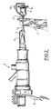
- la figure 2 représente un vérin de commande d'embrayage muni du dispositif de réglage proposé par l'invention,
- la figure 3A est une vue de détail de la figure 2, sur laquelle la rotule d'entraínement de la fourchette est représentée partiellement en coupe, et
- la figure 3B correspond à la figure 3A après le retrait de l'élément de calage provisoire.
- FIG. 1 illustrates the state of the art,
- FIG. 2 represents a clutch control cylinder fitted with the adjustment device proposed by the invention,
- FIG. 3A is a detailed view of FIG. 2, in which the fork drive ball joint is partially shown in section, and
- Figure 3B corresponds to Figure 3A after removal of the temporary wedging element.
Sur la figure 1, on a reproduit de façon schématique un vérin de
commande d'embrayage 1 de type connu, pouvant être fixé au
moyen d'une patte de fixation 2 sur une transmission de
véhicule (non représentée).In Figure 1, we have schematically reproduced a
Le vérin 1 est du type «simple effet». Sa tige d'actionnement 3,
solidaire d'un piston interne non représenté, coopère avec une
fourchette de débrayage 4, dont seule la partie supérieure
apparaít sur le schéma. De façon classique, le vérin 1 est au
repos en situation embrayée, et reçoit une pression d'huile pour
débrayer la transmission en tirant la fourchette 4 vers la gauche
de la figure. La tige 3 traverse la fourchette 4, et tire sur celle-ci
au moyen d'une rotule 6 prenant appui sur cette dernière. La
rotule 6 est immobilisée sur la tige 3 au moyen d'un clip de
réglage 7, engagé simultanément dans une rainure 8 de la
rotule 6, et dans l'une des gorges 9 ménagées sur une barrette
11 fixée à l'extrémité de la tige 3.
La figure 1 indique également la présence d'une bague 12 sertie
sur la tige du vérin 1, et d'une cale d'indexage 15 disposée
provisoirement entre le corps du vérin la et la bague 12, de
façon à positionner correctement la tige 3 avant le réglage de la
rotule. Cet indexage vise à garantir à la tige 3 du vérin une
course de fonctionnement suffisante vers la gauche et vers la
droite du schéma, pour débrayer, et pour rattraper à l'extrémité
de la fourchette le décalage imposé à celle-ci par l'usure
progressive des garnitures d'embrayage.Figure 1 also indicates the presence of a crimped
Le vérin illustré par la figure 1 et par la figure 2 peut notamment être utilisé dans un système d'embrayage automatique piloté électroniquement, mais peut également être commandé mécaniquement.The cylinder illustrated in FIG. 1 and in FIG. 2 can especially be used in a clutch system automatic electronically controlled, but can also be mechanically controlled.
Comme indiqué précédemment, selon l'état de la technique
connue, l'ajustement en position de la rotule 6 sur la tige 3 est
laissé au soin de l'opérateur, qui choisit à cet effet la gorge 9
appropriée.As indicated above, according to the state of the art
known, the adjustment in position of the
Sur la figure 2, on retrouve les mêmes éléments que sur la
figure 1 à gauche de la fourchette 4, mais la partie droite du
schéma fait apparaítre un nouvel élément, constitué par un
élément provisoire de calage 13 de l'élément d'entraínement ou
rotule d'entraínement 6, de la fourchette 4.On figure 2, we find the same elements as on the
figure 1 to the left of fork 4, but the right part of
diagram shows a new element, consisting of a
Conformément à l'invention, le dispositif de réglage illustré par
la figure 2 comporte en effet une cale 13 maintenant
provisoirement l'élément d'entraínement 6 de la fourchette 4
dans une position d'attente sur une partie 11 de la tige 3, telle
qu'une barrette 11 fixée à l'extrémité de celle-ci.In accordance with the invention, the adjustment device illustrated by
Figure 2 has indeed a
L'élément d'entraínement 6, se présente par exemple, mais sans
aucune obligation sous la forme d'une rotule, qui peut se
déplacer sur la barrette 11 jusqu'à la fourchette 4 sous l'action
d'un ressort 14 apparaissant plus clairement sur les figures 3A
et 3B. Le ressort 14 prend appui sur une coupelle 16 fixée à
l'extrémité de la barrette. Ce déplacement n'est toutefois
possible qu'après le retrait de l'élément de calage provisoire 13.The
Comme indiqué sur les figures 3A et 3B, la barrette 11 peut
avantageusement être «en pied de sapin», de sorte que
l'élément 6 peut être repoussé élastiquement par le ressort 14
contre la fourchette 4, sans possibilité de retour dans la
direction opposée.As indicated in FIGS. 3A and 3B, the
Plus précisément, le ressort 14 prend appui sur la coupelle
d'arrêt 16 et sur un élément d'arrêt 17 solidaire de la rotule 6. More specifically, the
L'élément de calage maintient donc provisoirement le ressort
14, et la rotule d'entraínement 6 contre la coupelle d'arrêt 16,
avant que le ressort ne repousse automatiquement la rotule
contre la fourchette, en faisant glisser celle-ci sur la barrette en
pied de sapin 11.The wedging element therefore temporarily holds the
Sur la figure 2, on retrouve la cale d'indexage 15 de la figure 1,
destinée à être retirée après le réglage faisant l'objet de
l'invention, et avant la mise en service de l'embrayage. En effet,
l'indexage de la tige du vérin (qui vise non pas à tenir compte
des dispersions de position de la fourchette à l'état neuf, mais à
permettre le rattrapage d'usure de l'embrayage en cours de
fonctionnement) n'est pas directement concerné par les mesures
proposées, et reste dans tous les cas un préalable nécessaire au
réglage proprement dit concerné par l'invention.In FIG. 2, we find the indexing
Les mesures proposées par l'invention pour effectuer ce réglage
consistent principalement à retenir dans un premier temps la
rotule d'entraínement 6 à l'écart de la fourchette 4 au moyen de
la cale 13, avant de retirer cette cale pour laisser la rotule 6
trouver automatiquement sur la tige 3 l'emplacement dans
lequel elle ne présente aucun jeu vis-à-vis de la fourchette 4 en
situation embrayée. Conformément à l'invention, cet
emplacement est conservé jusqu'à l'opération de réglage
suivante, étant donné que la structure de la barrette interdit à la
rotule de s'écarter de la fourchette. The measures proposed by the invention to effect this adjustment
mainly consist in initially retaining the
L'invention permet donc de simplifier le montage d'un vérin de commande d'embrayage, en remplaçant une opération d'ajustement manuel qui nécessite l'attention particulière d'un opérateur, par un réglage automatique particulièrement fiable, qui autorise un gain de temps non négligeable sur la chaíne de montage.The invention therefore makes it possible to simplify the mounting of a cylinder clutch control, replacing an operation manual adjustment which requires the special attention of a operator, by a particularly reliable automatic adjustment, which allows a significant saving of time on the chain of mounting.
Claims (7)
Applications Claiming Priority (2)
| Application Number | Priority Date | Filing Date | Title |
|---|---|---|---|
| FR9702727 | 1997-03-07 | ||
| FR9702727A FR2760412B1 (en) | 1997-03-07 | 1997-03-07 | METHOD AND DEVICE FOR ADJUSTING A CLUTCH CONTROL JACK |
Publications (1)
| Publication Number | Publication Date |
|---|---|
| EP0863325A1 true EP0863325A1 (en) | 1998-09-09 |
Family
ID=9504519
Family Applications (1)
| Application Number | Title | Priority Date | Filing Date |
|---|---|---|---|
| EP98400472A Withdrawn EP0863325A1 (en) | 1997-03-07 | 1998-02-27 | Method and device for adjusting a clutch control cylinder |
Country Status (2)
| Country | Link |
|---|---|
| EP (1) | EP0863325A1 (en) |
| FR (1) | FR2760412B1 (en) |
Cited By (2)
| Publication number | Priority date | Publication date | Assignee | Title |
|---|---|---|---|---|
| FR2964915A1 (en) * | 2010-09-17 | 2012-03-23 | Peugeot Citroen Automobiles Sa | Device for adjusting length of clutch cable of terrestrial motor vehicle, has rod connected to body, where distance measured along axis of rod between shroud and body is modified by displacement of body that causes displacement of cable |
| FR3010948A1 (en) * | 2013-09-26 | 2015-03-27 | Peugeot Citroen Automobiles Sa | METHOD FOR ADJUSTING A CABLE CLUTCH CONTROL |
Families Citing this family (1)
| Publication number | Priority date | Publication date | Assignee | Title |
|---|---|---|---|---|
| US8089351B2 (en) | 2004-10-06 | 2012-01-03 | Johnson Controls Technology Company | Instrument cluster lens information, telltails, and lighting |
Citations (3)
| Publication number | Priority date | Publication date | Assignee | Title |
|---|---|---|---|---|
| US4854185A (en) * | 1988-10-17 | 1989-08-08 | Babcock Industries Inc. | Manually operated and locked conduit length adjuster system |
| WO1993025824A1 (en) * | 1992-06-05 | 1993-12-23 | Automotive Products Plc | A clutch actuation system and a cable therefor |
| FR2718202A1 (en) * | 1994-03-31 | 1995-10-06 | Rockwell Bcs France | Automatic unit to take up play in linear cable operating system |
-
1997
- 1997-03-07 FR FR9702727A patent/FR2760412B1/en not_active Expired - Fee Related
-
1998
- 1998-02-27 EP EP98400472A patent/EP0863325A1/en not_active Withdrawn
Patent Citations (3)
| Publication number | Priority date | Publication date | Assignee | Title |
|---|---|---|---|---|
| US4854185A (en) * | 1988-10-17 | 1989-08-08 | Babcock Industries Inc. | Manually operated and locked conduit length adjuster system |
| WO1993025824A1 (en) * | 1992-06-05 | 1993-12-23 | Automotive Products Plc | A clutch actuation system and a cable therefor |
| FR2718202A1 (en) * | 1994-03-31 | 1995-10-06 | Rockwell Bcs France | Automatic unit to take up play in linear cable operating system |
Cited By (2)
| Publication number | Priority date | Publication date | Assignee | Title |
|---|---|---|---|---|
| FR2964915A1 (en) * | 2010-09-17 | 2012-03-23 | Peugeot Citroen Automobiles Sa | Device for adjusting length of clutch cable of terrestrial motor vehicle, has rod connected to body, where distance measured along axis of rod between shroud and body is modified by displacement of body that causes displacement of cable |
| FR3010948A1 (en) * | 2013-09-26 | 2015-03-27 | Peugeot Citroen Automobiles Sa | METHOD FOR ADJUSTING A CABLE CLUTCH CONTROL |
Also Published As
| Publication number | Publication date |
|---|---|
| FR2760412A1 (en) | 1998-09-11 |
| FR2760412B1 (en) | 1999-04-16 |
Similar Documents
| Publication | Publication Date | Title |
|---|---|---|
| FR2756006A1 (en) | DEVICE FOR THE ELECTROMAGNETIC ACTUATION OF A LOAD CHANGE VALVE | |
| EP0065451A1 (en) | Brake pressure modulator for anti-skid systems | |
| EP0156666A1 (en) | Brake pressure regulator | |
| EP2202122A1 (en) | Railway brake cylinder | |
| EP0113261B1 (en) | Automatically adjusting disc brake | |
| EP0863325A1 (en) | Method and device for adjusting a clutch control cylinder | |
| WO2004026653A1 (en) | Pneumatic brake booster | |
| EP0186537B1 (en) | Disc brake | |
| EP2314488A1 (en) | Braking system comprising a master cylinder | |
| EP0069657B1 (en) | Drum brake | |
| CA3135534A1 (en) | Connecting device with an intermediate unlocking position | |
| EP0163566A1 (en) | Disc brake with automatic adjuster | |
| EP0333525A1 (en) | Connection between an actuating pedal and a translatory mobile controlling member | |
| EP2090799B1 (en) | Drum brake for an automotive vehicle and vehicle equipped with such a brake | |
| EP0835482B1 (en) | Pressure regulator electrovalve for hydraulic circuit | |
| EP0037755A1 (en) | Floating caliper disc brake | |
| EP0192546B1 (en) | Hydraulic brake booster | |
| EP0175600A1 (en) | Slack adjuster for disc-brakes | |
| EP0146444B1 (en) | Fixing device for a brake strut provided with an automatic adjuster for a drum brake shoe | |
| FR2492757A2 (en) | ASSISTED BRAKE UNIT FOR MOTOR VEHICLES | |
| EP0648170B1 (en) | Force transmission device with plane contact face | |
| FR2695693A1 (en) | Fastening device for cable cover on support - comprises stop part in form of elastic ring or plain ring with band mounted slidably on cylindrical part of cover which also has socket | |
| EP1429946A1 (en) | Tandem master cylinder for electrohydraulic braking system | |
| EP1426227A2 (en) | Mounting device for a return spring for a vehicle gearshift lever | |
| FR2681116A1 (en) | Device for operating a disc brake for a vehicle |
Legal Events
| Date | Code | Title | Description |
|---|---|---|---|
| PUAI | Public reference made under article 153(3) epc to a published international application that has entered the european phase |
Free format text: ORIGINAL CODE: 0009012 |
|
| AK | Designated contracting states |
Kind code of ref document: A1 Designated state(s): BE DE |
|
| AX | Request for extension of the european patent |
Free format text: AL;LT;LV;MK;RO;SI |
|
| 17P | Request for examination filed |
Effective date: 19990304 |
|
| AKX | Designation fees paid |
Free format text: BE DE |
|
| RBV | Designated contracting states (corrected) |
Designated state(s): BE DE |
|
| 17Q | First examination report despatched |
Effective date: 20010706 |
|
| RAP1 | Party data changed (applicant data changed or rights of an application transferred) |
Owner name: RENAULT S.A.S. |
|
| GRAH | Despatch of communication of intention to grant a patent |
Free format text: ORIGINAL CODE: EPIDOS IGRA |
|
| STAA | Information on the status of an ep patent application or granted ep patent |
Free format text: STATUS: THE APPLICATION HAS BEEN WITHDRAWN |
|
| 18W | Application withdrawn |
Effective date: 20030108 |