EP0863221A1 - High-Cr precision casting materials and turbine blades - Google Patents
High-Cr precision casting materials and turbine blades Download PDFInfo
- Publication number
- EP0863221A1 EP0863221A1 EP98103275A EP98103275A EP0863221A1 EP 0863221 A1 EP0863221 A1 EP 0863221A1 EP 98103275 A EP98103275 A EP 98103275A EP 98103275 A EP98103275 A EP 98103275A EP 0863221 A1 EP0863221 A1 EP 0863221A1
- Authority
- EP
- European Patent Office
- Prior art keywords
- precision casting
- turbine blade
- materials
- shroud
- present
- Prior art date
- Legal status (The legal status is an assumption and is not a legal conclusion. Google has not performed a legal analysis and makes no representation as to the accuracy of the status listed.)
- Granted
Links
Images


Classifications
-
- F—MECHANICAL ENGINEERING; LIGHTING; HEATING; WEAPONS; BLASTING
- F01—MACHINES OR ENGINES IN GENERAL; ENGINE PLANTS IN GENERAL; STEAM ENGINES
- F01D—NON-POSITIVE DISPLACEMENT MACHINES OR ENGINES, e.g. STEAM TURBINES
- F01D5/00—Blades; Blade-carrying members; Heating, heat-insulating, cooling or antivibration means on the blades or the members
- F01D5/12—Blades
- F01D5/28—Selecting particular materials; Particular measures relating thereto; Measures against erosion or corrosion
-
- C—CHEMISTRY; METALLURGY
- C22—METALLURGY; FERROUS OR NON-FERROUS ALLOYS; TREATMENT OF ALLOYS OR NON-FERROUS METALS
- C22C—ALLOYS
- C22C38/00—Ferrous alloys, e.g. steel alloys
- C22C38/18—Ferrous alloys, e.g. steel alloys containing chromium
- C22C38/40—Ferrous alloys, e.g. steel alloys containing chromium with nickel
- C22C38/52—Ferrous alloys, e.g. steel alloys containing chromium with nickel with cobalt
-
- F—MECHANICAL ENGINEERING; LIGHTING; HEATING; WEAPONS; BLASTING
- F01—MACHINES OR ENGINES IN GENERAL; ENGINE PLANTS IN GENERAL; STEAM ENGINES
- F01D—NON-POSITIVE DISPLACEMENT MACHINES OR ENGINES, e.g. STEAM TURBINES
- F01D5/00—Blades; Blade-carrying members; Heating, heat-insulating, cooling or antivibration means on the blades or the members
- F01D5/12—Blades
- F01D5/14—Form or construction
- F01D5/18—Hollow blades, i.e. blades with cooling or heating channels or cavities; Heating, heat-insulating or cooling means on blades
-
- F—MECHANICAL ENGINEERING; LIGHTING; HEATING; WEAPONS; BLASTING
- F05—INDEXING SCHEMES RELATING TO ENGINES OR PUMPS IN VARIOUS SUBCLASSES OF CLASSES F01-F04
- F05D—INDEXING SCHEME FOR ASPECTS RELATING TO NON-POSITIVE-DISPLACEMENT MACHINES OR ENGINES, GAS-TURBINES OR JET-PROPULSION PLANTS
- F05D2300/00—Materials; Properties thereof
- F05D2300/10—Metals, alloys or intermetallic compounds
- F05D2300/11—Iron
-
- F—MECHANICAL ENGINEERING; LIGHTING; HEATING; WEAPONS; BLASTING
- F05—INDEXING SCHEMES RELATING TO ENGINES OR PUMPS IN VARIOUS SUBCLASSES OF CLASSES F01-F04
- F05D—INDEXING SCHEME FOR ASPECTS RELATING TO NON-POSITIVE-DISPLACEMENT MACHINES OR ENGINES, GAS-TURBINES OR JET-PROPULSION PLANTS
- F05D2300/00—Materials; Properties thereof
- F05D2300/10—Metals, alloys or intermetallic compounds
- F05D2300/13—Refractory metals, i.e. Ti, V, Cr, Zr, Nb, Mo, Hf, Ta, W
- F05D2300/132—Chromium
Abstract
Description
| Group | Test material No. | C | Si | Mn | Cr | Ni | V | Nb | Mo | W | Co | N |
| Inventive materials (1) | 1 | 0.12 | 0.19 | 0.60 | 9.3 | 0.48 | 0.12 | 0.04 | 0.32 | 2.1 | 1.5 | 0.052 |
| 2 | 0.13 | 0.15 | 0.03 | 8.5 | 0.55 | 0.12 | 0.04 | 0.27 | 1.8 | 1.9 | 0.064 | |
| 3 | 0.13 | 0.14 | 0.90 | 8.6 | 0.06 | 0.13 | 0.05 | 0.32 | 1.8 | 1.9 | 0.050 | |
| 4 | 0.09 | 0.19 | 0.55 | 9.1 | 0.54 | 0.14 | 0.05 | 0.32 | 2.2 | 3.8 | 0.067 | |
| 5 | 0.14 | 0.12 | 0.61 | 8.7 | 0.60 | 0.14 | 0.06 | 0.29 | 2.1 | 0.5 | 0.069 | |
| 6 | 0.12 | 0.26 | 0.34 | 9.2 | 0.56 | 0.19 | 0.06 | 0.31 | 1.7 | 1.7 | 0.035 | |
| 7 | 0.12 | 0.18 | 0.63 | 9.3 | 0.55 | 0.13 | 0.05 | 0.29 | 2.2 | 3.5 | 0.054 | |
| Comparative materials | 11 | 0.11 | 0.18 | 0.60 | 10.6 | 0.21 | 0.14 | 0.05 | 0.20 | 0.6 | 0.5 | 0.013 |
| 12 | 0.25 | 0.38 | 1.06 | 9.1 | 0.40 | 0.18 | 0.09 | 0.83 | 2.9 | 1.8 | 0.082 | |
| 13 | 0.06 | 0.28 | 0.15 | 9.5 | 0.16 | 0.17 | 0.05 | 0.45 | 2.8 | 0.5 | 0.026 | |
| 14 | 0.09 | 0.65 | 0.56 | 9.4 | 0.44 | 0.25 | 0.04 | 0.56 | 1.2 | 1.0 | 0.045 | |
| 15 | 0.07 | 0.45 | 0.04 | 9.2 | 0.05 | 0.22 | 0.05 | 0.33 | 2.0 | 0.1 | 0.032 | |
| 16 | 0.10 | 0.36 | 0.46 | 8.4 | 0.54 | 0.15 | 0.04 | 0.06 | 1.5 | 1.2 | 0.055 | |
| 17 | 0.11 | 0.28 | 0.68 | 9.1 | 0.85 | 0.15 | 0.04 | 0.54 | 1.3 | 5.5 | 0.065 | |
| 18 | 0.13 | 0.29 | 0.88 | 9.2 | 0.68 | 0.08 | 0.04 | 0.08 | 1.5 | 4.2 | 0.054 |

| Group | Test material No. | C | Si | Mn | Cr | Ni | V | Nb | Mo | W | Co | B | N |
| Inventive materials (1) | 1 | 0.12 | 0.19 | 0.60 | 9.3 | 0.48 | 0.12 | 0.04 | 0.32 | 2.1 | 1.5 | - | 0.052 |
| 4 | 0.09 | 0.19 | 0.55 | 9.1 | 0.54 | 0.14 | 0.05 | 0.32 | 2.2 | 3.8 | - | 0.067 | |
| 5 | 0.14 | 0.12 | 0.61 | 8.7 | 0.60 | 0.14 | 0.06 | 0.29 | 2.1 | 0.5 | - | 0.069 | |
| 7 | 0.12 | 0.18 | 0.63 | 9.3 | 0.55 | 0.13 | 0.05 | 0.29 | 2.2 | 3.5 | - | 0.054 | |
| Inventive materials (2) | 21 | 0.12 | 0.18 | 0.62 | 9.2 | 0.46 | 0.12 | 0.04 | 0.31 | 2.1 | 1.4 | 0.003 | 0.053 |
| 22 | 0.09 | 0.19 | 0.57 | 9.1 | 0.56 | 0.13 | 0.04 | 0.34 | 2.2 | 3.7 | 0.006 | 0.064 | |
| 23 | 0.13 | 0.13 | 0.61 | 8.8 | 0.60 | 0.14 | 0.05 | 0.29 | 2.1 | 0.7 | 0.005 | 0.068 | |
| 24 | 0.12 | 0.18 | 0.65 | 9.3 | 0.54 | 0.13 | 0.05 | 0.27 | 2.2 | 3.5 | 0.007 | 0.052 | |
| 25 | 0.13 | 0.14 | 0.64 | 9.1 | 0.50 | 0.14 | 0.05 | 0.35 | 1.8 | 1.7 | 0.009 | 0.051 |

Claims (7)
- A high-Cr precision casting material consisting essentially of, on a weight percentage basis, 0.08 to 0.14% carbon, 0.1 to 0.3% silicon, 0.01 to 1% manganese, 8.5 (inclusive) to 9.5% (not inclusive) chromium, 0.01 to 0.6% nickel, 0.1 to 0.2% vanadium, 0.03 to 0.06% niobium, 0.02 to 0.07% nitrogen, 0.1 to 0.7% molybdenum, 1 to 2.5% tungsten, 0.01 to 4% cobalt, and the balance being iron and incidental impurities.
- A high-Cr precision casting material consisting essentially of, on a weight percentage basis, 0.08 to 0.14% carbon, 0.1 to 0.3% silicon, 0.01 to 1% manganese, 8.5 (inclusive) to 9.5% (not inclusive) chromium, 0.01 to 0.6% nickel, 0.1 to 0.2% vanadium, 0.03 to 0.06% niobium, 0.02 to 0.07% nitrogen, 0.1 to 0.7% molybdenum, 1 to 2.5% tungsten, 0.01 to 4% cobalt, 0.002 to 0.01% boron, and the balance being iron and incidental impurities.
- A turbine blade made by a precision casting process using the high-Cr precision casting material of claim 1 or 2.
- A turbine blade having an airfoil of hollow structure, said turbine blade being made by a precision casting process using the high-Cr precision casting material of claim 1 or 2.
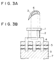
- A turbine blade obtained by making a turbine blade having airfoils of hollow structure and a shroud with a depression formed in the surface thereof according to a precision casting process using the high-Cr precision casting material of claim 1 or 2, and mounting a metallic plate (or shroud cover) in the depression of the shroud.
- A precision casting made of a material which comprises:from 0.08 to 0.14 wt % carbon;from 0.1 to 0.3 wt % silicon;from 0.01 to 1 wt % manganese;from 8.5 to 9.5 wt % chromium;from 0.01 to 0.6 wt % nickel;from 0.1 to 0.7 wt % molybdenum;from 1 to 2.5 wt % tungsten;from 0.01 to 4 wt % cobalt;optionally, from 0.002 to 0.01 wt % boron;balance iron, together with incidental elements and impurities (if any).
- A method of precision casting, characterised by the step of using, as casting material, a casting material as claimed in claim 1 or 2.
Applications Claiming Priority (3)
| Application Number | Priority Date | Filing Date | Title |
|---|---|---|---|
| JP9050428A JPH10245658A (en) | 1997-03-05 | 1997-03-05 | High cr precision casting material and turbine blade |
| JP50428/97 | 1997-03-05 | ||
| JP5042897 | 1997-03-05 |
Publications (2)
| Publication Number | Publication Date |
|---|---|
| EP0863221A1 true EP0863221A1 (en) | 1998-09-09 |
| EP0863221B1 EP0863221B1 (en) | 2000-05-03 |
Family
ID=12858605
Family Applications (1)
| Application Number | Title | Priority Date | Filing Date |
|---|---|---|---|
| EP98103275A Expired - Lifetime EP0863221B1 (en) | 1997-03-05 | 1998-02-25 | Turbine blades |
Country Status (7)
| Country | Link |
|---|---|
| US (1) | US6095756A (en) |
| EP (1) | EP0863221B1 (en) |
| JP (1) | JPH10245658A (en) |
| AT (1) | ATE192508T1 (en) |
| CZ (1) | CZ290459B6 (en) |
| DE (1) | DE69800133T2 (en) |
| ES (1) | ES2149023T3 (en) |
Cited By (3)
| Publication number | Priority date | Publication date | Assignee | Title |
|---|---|---|---|---|
| EP1347073A1 (en) * | 2000-12-26 | 2003-09-24 | The Japan Steel Works, Ltd. | HIGH Cr FERRITIC HEAT RESISTANCE STEEL |
| US7281901B2 (en) | 2004-12-29 | 2007-10-16 | Caterpillar Inc. | Free-form welded power system component |
| EP3112597A1 (en) | 2015-07-02 | 2017-01-04 | Airbus Defence and Space GmbH | Temperature-resistant turbine blade made with a layer of oxide ceramics |
Families Citing this family (7)
| Publication number | Priority date | Publication date | Assignee | Title |
|---|---|---|---|---|
| US20040115059A1 (en) * | 2002-12-12 | 2004-06-17 | Kehl Richard Eugene | Cored steam turbine bucket |
| US7104762B2 (en) * | 2004-01-06 | 2006-09-12 | General Electric Company | Reduced weight control stage for a high temperature steam turbine |
| US20060088409A1 (en) * | 2004-10-21 | 2006-04-27 | General Electric Company | Grouped reaction nozzle tip shrouds with integrated seals |
| US20070071605A1 (en) * | 2005-09-23 | 2007-03-29 | General Electric Company | Integrated nozzle and bucket wheels for reaction steam turbine stationary components and related method |
| CN101629573B (en) * | 2009-08-07 | 2011-08-10 | 宁波甬微集团有限公司 | Slip sheet of refrigeration compressor and manufacturing method thereof |
| JP2015227627A (en) * | 2014-05-30 | 2015-12-17 | 株式会社東芝 | Rotary machine |
| JP2017159350A (en) * | 2016-03-11 | 2017-09-14 | 株式会社神戸製鋼所 | Weld metal, and weld structure including weld metal |
Citations (4)
| Publication number | Priority date | Publication date | Assignee | Title |
|---|---|---|---|---|
| JPH04371552A (en) * | 1991-06-18 | 1992-12-24 | Nippon Steel Corp | High strength ferritic heat resisting steel |
| JPH08333657A (en) * | 1995-04-03 | 1996-12-17 | Japan Steel Works Ltd:The | Heat resistant cast steel and its production |
| JPH0931600A (en) * | 1995-07-17 | 1997-02-04 | Mitsubishi Heavy Ind Ltd | Steam turbine rotor material for high temperature use |
| JPH0959747A (en) * | 1995-08-25 | 1997-03-04 | Hitachi Ltd | High strength heat resistant cast steel, steam turbine casing, steam turbine electric power plant, and steam turbine |
Family Cites Families (17)
| Publication number | Priority date | Publication date | Assignee | Title |
|---|---|---|---|---|
| US3810711A (en) * | 1972-09-22 | 1974-05-14 | Gen Motors Corp | Cooled turbine blade and its manufacture |
| GB1483532A (en) * | 1974-09-13 | 1977-08-24 | Rolls Royce | Stator structure for a gas turbine engine |
| US4218178A (en) * | 1978-03-31 | 1980-08-19 | General Motors Corporation | Turbine vane structure |
| US4693667A (en) * | 1980-04-29 | 1987-09-15 | Teledyne Industries, Inc. | Turbine inlet nozzle with cooling means |
| EP0084234A1 (en) * | 1981-12-16 | 1983-07-27 | Vickers Plc | Investment casting process and mould |
| JPS61231139A (en) * | 1985-04-06 | 1986-10-15 | Nippon Steel Corp | Heat resistant ferritic steel of high strength |
| US4761116A (en) * | 1987-05-11 | 1988-08-02 | General Electric Company | Turbine blade with tip vent |
| JPH0639885B2 (en) * | 1988-03-14 | 1994-05-25 | 株式会社日立製作所 | Gas turbine shroud and gas turbine |
| US5173255A (en) * | 1988-10-03 | 1992-12-22 | General Electric Company | Cast columnar grain hollow nickel base alloy articles and alloy and heat treatment for making |
| US5226789A (en) * | 1991-05-13 | 1993-07-13 | General Electric Company | Composite fan stator assembly |
| US5310431A (en) * | 1992-10-07 | 1994-05-10 | Robert F. Buck | Creep resistant, precipitation-dispersion-strengthened, martensitic stainless steel and method thereof |
| US5350277A (en) * | 1992-11-20 | 1994-09-27 | General Electric Company | Closed-circuit steam-cooled bucket with integrally cooled shroud for gas turbines and methods of steam-cooling the buckets and shrouds |
| US5415706A (en) * | 1993-05-28 | 1995-05-16 | Abb Management Ag | Heat- and creep-resistant steel having a martensitic microstructure produced by a heat-treatment process |
| JP3110227B2 (en) * | 1993-11-22 | 2000-11-20 | 株式会社東芝 | Turbine cooling blade |
| JP3315800B2 (en) * | 1994-02-22 | 2002-08-19 | 株式会社日立製作所 | Steam turbine power plant and steam turbine |
| JPH08135402A (en) * | 1994-11-11 | 1996-05-28 | Mitsubishi Heavy Ind Ltd | Gas turbine stationary blade structure |
| JP3358951B2 (en) * | 1996-09-10 | 2002-12-24 | 三菱重工業株式会社 | High strength, high toughness heat-resistant cast steel |
-
1997
- 1997-03-05 JP JP9050428A patent/JPH10245658A/en not_active Withdrawn
-
1998
- 1998-02-25 ES ES98103275T patent/ES2149023T3/en not_active Expired - Lifetime
- 1998-02-25 EP EP98103275A patent/EP0863221B1/en not_active Expired - Lifetime
- 1998-02-25 DE DE69800133T patent/DE69800133T2/en not_active Expired - Fee Related
- 1998-02-25 AT AT98103275T patent/ATE192508T1/en not_active IP Right Cessation
- 1998-03-03 US US09/034,065 patent/US6095756A/en not_active Expired - Fee Related
- 1998-03-03 CZ CZ1998634A patent/CZ290459B6/en not_active IP Right Cessation
Patent Citations (4)
| Publication number | Priority date | Publication date | Assignee | Title |
|---|---|---|---|---|
| JPH04371552A (en) * | 1991-06-18 | 1992-12-24 | Nippon Steel Corp | High strength ferritic heat resisting steel |
| JPH08333657A (en) * | 1995-04-03 | 1996-12-17 | Japan Steel Works Ltd:The | Heat resistant cast steel and its production |
| JPH0931600A (en) * | 1995-07-17 | 1997-02-04 | Mitsubishi Heavy Ind Ltd | Steam turbine rotor material for high temperature use |
| JPH0959747A (en) * | 1995-08-25 | 1997-03-04 | Hitachi Ltd | High strength heat resistant cast steel, steam turbine casing, steam turbine electric power plant, and steam turbine |
Non-Patent Citations (4)
| Title |
|---|
| PATENT ABSTRACTS OF JAPAN vol. 017, no. 247 (C - 1059) 18 May 1993 (1993-05-18) * |
| PATENT ABSTRACTS OF JAPAN vol. 097, no. 004 30 April 1997 (1997-04-30) * |
| PATENT ABSTRACTS OF JAPAN vol. 097, no. 006 30 June 1997 (1997-06-30) * |
| PATENT ABSTRACTS OF JAPAN vol. 097, no. 007 31 July 1997 (1997-07-31) * |
Cited By (5)
| Publication number | Priority date | Publication date | Assignee | Title |
|---|---|---|---|---|
| EP1347073A1 (en) * | 2000-12-26 | 2003-09-24 | The Japan Steel Works, Ltd. | HIGH Cr FERRITIC HEAT RESISTANCE STEEL |
| EP1347073A4 (en) * | 2000-12-26 | 2006-01-18 | Japan Steel Works Ltd | HIGH Cr FERRITIC HEAT RESISTANCE STEEL |
| US7820098B2 (en) | 2000-12-26 | 2010-10-26 | The Japan Steel Works, Ltd. | High Cr ferritic heat resistance steel |
| US7281901B2 (en) | 2004-12-29 | 2007-10-16 | Caterpillar Inc. | Free-form welded power system component |
| EP3112597A1 (en) | 2015-07-02 | 2017-01-04 | Airbus Defence and Space GmbH | Temperature-resistant turbine blade made with a layer of oxide ceramics |
Also Published As
| Publication number | Publication date |
|---|---|
| US6095756A (en) | 2000-08-01 |
| DE69800133D1 (en) | 2000-06-08 |
| CZ290459B6 (en) | 2002-07-17 |
| CZ63498A3 (en) | 1999-11-17 |
| EP0863221B1 (en) | 2000-05-03 |
| DE69800133T2 (en) | 2000-11-09 |
| ATE192508T1 (en) | 2000-05-15 |
| ES2149023T3 (en) | 2000-10-16 |
| JPH10245658A (en) | 1998-09-14 |
Similar Documents
| Publication | Publication Date | Title |
|---|---|---|
| EP0384433B1 (en) | Ferritic heat resisting steel having superior high-temperature strength | |
| JP3354832B2 (en) | High toughness ferritic heat-resistant steel | |
| EP1001044B1 (en) | Use of a heat-resisting cast steel | |
| US6095756A (en) | High-CR precision casting materials and turbine blades | |
| US6350325B1 (en) | Turbine shaft and method for producing a turbine shaft | |
| US5882586A (en) | Heat-resistant nickel-based alloy excellent in weldability | |
| US4857120A (en) | Heat-resisting steel turbine part | |
| EP2204462A1 (en) | Ni-based alloy for a forged part of a steam turbine with excellent high temperature strength, forgeability and weldability, rotor blade of a steam turbine, stator blade of a steam turbine, screw member for a steam turbine, and pipe for a steam turbine | |
| CN101111618B (en) | Niobium addition in crmo 1/4 v steel castings for steam turbine casing appliations | |
| US6106766A (en) | Material for gas turbine disk | |
| JP3422658B2 (en) | Heat resistant steel | |
| JPH0672286B2 (en) | ▲ High ▼ Austenitic stainless steel with excellent temperature strength | |
| US20010041137A1 (en) | Steam turbine rotor shaft | |
| JPS616256A (en) | 12% cr heat resisting steel | |
| JP3245097B2 (en) | High temperature steam turbine rotor material | |
| JP2001049398A (en) | High toughness heat resistant steel, and manufacture of turbine rotor | |
| JPH06256893A (en) | High toughness low alloy steel excellent in high temperature strength | |
| JPH1018003A (en) | Gas turbine, gas turbine disk, and their production | |
| JPH0641678A (en) | Turbine rotor | |
| JPH02149649A (en) | Cr alloy steel | |
| JPS61217554A (en) | Heat resistant 12cr steel | |
| Ishii et al. | High strength 12% Cr heat resisting steel for high temperature steam turbine blade | |
| JPS61221355A (en) | 12cr heat resisting steel | |
| JPH0570902A (en) | High cr alloy steel | |
| JPH0650041B2 (en) | Gas turbine |
Legal Events
| Date | Code | Title | Description |
|---|---|---|---|
| PUAI | Public reference made under article 153(3) epc to a published international application that has entered the european phase |
Free format text: ORIGINAL CODE: 0009012 |
|
| 17P | Request for examination filed |
Effective date: 19980225 |
|
| AK | Designated contracting states |
Kind code of ref document: A1 Designated state(s): AT BE CH DE ES FR GB IT LI NL SE |
|
| AX | Request for extension of the european patent |
Free format text: AL;LT;LV;MK;RO;SI |
|
| 17Q | First examination report despatched |
Effective date: 19981126 |
|
| AKX | Designation fees paid |
Free format text: AT BE CH DE ES FR GB IT LI NL SE |
|
| RBV | Designated contracting states (corrected) |
Designated state(s): AT BE CH DE ES FR GB IT LI NL SE |
|
| RTI1 | Title (correction) |
Free format text: TURBINE BLADES |
|
| GRAG | Despatch of communication of intention to grant |
Free format text: ORIGINAL CODE: EPIDOS AGRA |
|
| GRAG | Despatch of communication of intention to grant |
Free format text: ORIGINAL CODE: EPIDOS AGRA |
|
| GRAG | Despatch of communication of intention to grant |
Free format text: ORIGINAL CODE: EPIDOS AGRA |
|
| GRAH | Despatch of communication of intention to grant a patent |
Free format text: ORIGINAL CODE: EPIDOS IGRA |
|
| RTI1 | Title (correction) |
Free format text: TURBINE BLADES |
|
| GRAG | Despatch of communication of intention to grant |
Free format text: ORIGINAL CODE: EPIDOS AGRA |
|
| GRAH | Despatch of communication of intention to grant a patent |
Free format text: ORIGINAL CODE: EPIDOS IGRA |
|
| GRAH | Despatch of communication of intention to grant a patent |
Free format text: ORIGINAL CODE: EPIDOS IGRA |
|
| GRAA | (expected) grant |
Free format text: ORIGINAL CODE: 0009210 |
|
| AK | Designated contracting states |
Kind code of ref document: B1 Designated state(s): AT BE CH DE ES FR GB IT LI NL SE |
|
| REF | Corresponds to: |
Ref document number: 192508 Country of ref document: AT Date of ref document: 20000515 Kind code of ref document: T |
|
| REG | Reference to a national code |
Ref country code: CH Ref legal event code: EP |
|
| REF | Corresponds to: |
Ref document number: 69800133 Country of ref document: DE Date of ref document: 20000608 |
|
| REG | Reference to a national code |
Ref country code: CH Ref legal event code: NV Representative=s name: BUECHEL, KAMINSKI & PARTNER PATENTANWAELTE EST |
|
| ITF | It: translation for a ep patent filed |
Owner name: MARCHI & PARTNERS S.R.L. |
|
| ET | Fr: translation filed | ||
| REG | Reference to a national code |
Ref country code: GB Ref legal event code: 746 Effective date: 20000911 |
|
| REG | Reference to a national code |
Ref country code: ES Ref legal event code: FG2A Ref document number: 2149023 Country of ref document: ES Kind code of ref document: T3 |
|
| REG | Reference to a national code |
Ref country code: FR Ref legal event code: D6 |
|
| PLBE | No opposition filed within time limit |
Free format text: ORIGINAL CODE: 0009261 |
|
| STAA | Information on the status of an ep patent application or granted ep patent |
Free format text: STATUS: NO OPPOSITION FILED WITHIN TIME LIMIT |
|
| 26N | No opposition filed | ||
| REG | Reference to a national code |
Ref country code: GB Ref legal event code: IF02 |
|
| PGFP | Annual fee paid to national office [announced via postgrant information from national office to epo] |
Ref country code: SE Payment date: 20030205 Year of fee payment: 6 |
|
| PGFP | Annual fee paid to national office [announced via postgrant information from national office to epo] |
Ref country code: FR Payment date: 20030210 Year of fee payment: 6 |
|
| PGFP | Annual fee paid to national office [announced via postgrant information from national office to epo] |
Ref country code: AT Payment date: 20030212 Year of fee payment: 6 |
|
| PGFP | Annual fee paid to national office [announced via postgrant information from national office to epo] |
Ref country code: GB Payment date: 20030219 Year of fee payment: 6 |
|
| PGFP | Annual fee paid to national office [announced via postgrant information from national office to epo] |
Ref country code: NL Payment date: 20030226 Year of fee payment: 6 Ref country code: ES Payment date: 20030226 Year of fee payment: 6 |
|
| PGFP | Annual fee paid to national office [announced via postgrant information from national office to epo] |
Ref country code: CH Payment date: 20030228 Year of fee payment: 6 |
|
| PGFP | Annual fee paid to national office [announced via postgrant information from national office to epo] |
Ref country code: DE Payment date: 20030306 Year of fee payment: 6 |
|
| PGFP | Annual fee paid to national office [announced via postgrant information from national office to epo] |
Ref country code: BE Payment date: 20030425 Year of fee payment: 6 |
|
| PG25 | Lapsed in a contracting state [announced via postgrant information from national office to epo] |
Ref country code: GB Free format text: LAPSE BECAUSE OF NON-PAYMENT OF DUE FEES Effective date: 20040225 Ref country code: AT Free format text: LAPSE BECAUSE OF NON-PAYMENT OF DUE FEES Effective date: 20040225 |
|
| PG25 | Lapsed in a contracting state [announced via postgrant information from national office to epo] |
Ref country code: SE Free format text: LAPSE BECAUSE OF NON-PAYMENT OF DUE FEES Effective date: 20040226 Ref country code: ES Free format text: LAPSE BECAUSE OF NON-PAYMENT OF DUE FEES Effective date: 20040226 |
|
| PG25 | Lapsed in a contracting state [announced via postgrant information from national office to epo] |
Ref country code: BE Free format text: LAPSE BECAUSE OF NON-PAYMENT OF DUE FEES Effective date: 20040228 |
|
| PG25 | Lapsed in a contracting state [announced via postgrant information from national office to epo] |
Ref country code: LI Free format text: LAPSE BECAUSE OF NON-PAYMENT OF DUE FEES Effective date: 20040229 Ref country code: CH Free format text: LAPSE BECAUSE OF NON-PAYMENT OF DUE FEES Effective date: 20040229 |
|
| BERE | Be: lapsed |
Owner name: *MITSUBISHI HEAVY INDUSTRIES LTD Effective date: 20040228 |
|
| PG25 | Lapsed in a contracting state [announced via postgrant information from national office to epo] |
Ref country code: NL Free format text: LAPSE BECAUSE OF NON-PAYMENT OF DUE FEES Effective date: 20040901 Ref country code: DE Free format text: LAPSE BECAUSE OF NON-PAYMENT OF DUE FEES Effective date: 20040901 |
|
| EUG | Se: european patent has lapsed | ||
| GBPC | Gb: european patent ceased through non-payment of renewal fee |
Effective date: 20040225 |
|
| REG | Reference to a national code |
Ref country code: CH Ref legal event code: PL |
|
| PG25 | Lapsed in a contracting state [announced via postgrant information from national office to epo] |
Ref country code: FR Free format text: LAPSE BECAUSE OF NON-PAYMENT OF DUE FEES Effective date: 20041029 |
|
| NLV4 | Nl: lapsed or anulled due to non-payment of the annual fee |
Effective date: 20040901 |
|
| REG | Reference to a national code |
Ref country code: FR Ref legal event code: ST |
|
| PG25 | Lapsed in a contracting state [announced via postgrant information from national office to epo] |
Ref country code: IT Free format text: LAPSE BECAUSE OF NON-PAYMENT OF DUE FEES;WARNING: LAPSES OF ITALIAN PATENTS WITH EFFECTIVE DATE BEFORE 2007 MAY HAVE OCCURRED AT ANY TIME BEFORE 2007. THE CORRECT EFFECTIVE DATE MAY BE DIFFERENT FROM THE ONE RECORDED. Effective date: 20050225 |
|
| REG | Reference to a national code |
Ref country code: ES Ref legal event code: FD2A Effective date: 20040226 |