EP0862361B1 - Alimenteur a vis presentant du profil ameliore pour remorque coupeuse, melangeuse et alimentatrice, destinee a l'ensilage de fourrage, d'herbe ou de paille - Google Patents
Alimenteur a vis presentant du profil ameliore pour remorque coupeuse, melangeuse et alimentatrice, destinee a l'ensilage de fourrage, d'herbe ou de paille Download PDFInfo
- Publication number
- EP0862361B1 EP0862361B1 EP96905862A EP96905862A EP0862361B1 EP 0862361 B1 EP0862361 B1 EP 0862361B1 EP 96905862 A EP96905862 A EP 96905862A EP 96905862 A EP96905862 A EP 96905862A EP 0862361 B1 EP0862361 B1 EP 0862361B1
- Authority
- EP
- European Patent Office
- Prior art keywords
- wagon
- screw
- spirals
- screw feeders
- spiral
- Prior art date
- Legal status (The legal status is an assumption and is not a legal conclusion. Google has not performed a legal analysis and makes no representation as to the accuracy of the status listed.)
- Expired - Lifetime
Links
- 244000025254 Cannabis sativa Species 0.000 title claims abstract description 6
- 239000004460 silage Substances 0.000 title claims abstract description 6
- 239000010902 straw Substances 0.000 title claims abstract description 6
- 239000000463 material Substances 0.000 claims abstract description 24
- 230000002093 peripheral effect Effects 0.000 claims abstract 2
- 239000000835 fiber Substances 0.000 description 4
- 238000000034 method Methods 0.000 description 3
- 239000011295 pitch Substances 0.000 description 3
- 238000010521 absorption reaction Methods 0.000 description 2
- 230000007423 decrease Effects 0.000 description 2
- 239000000203 mixture Substances 0.000 description 1
Images


Classifications
-
- A—HUMAN NECESSITIES
- A01—AGRICULTURE; FORESTRY; ANIMAL HUSBANDRY; HUNTING; TRAPPING; FISHING
- A01F—PROCESSING OF HARVESTED PRODUCE; HAY OR STRAW PRESSES; DEVICES FOR STORING AGRICULTURAL OR HORTICULTURAL PRODUCE
- A01F29/00—Cutting apparatus specially adapted for cutting hay, straw or the like
- A01F29/005—Cutting apparatus specially adapted for cutting hay, straw or the like for disintegrating and cutting up bales of hay, straw or fodder
-
- B—PERFORMING OPERATIONS; TRANSPORTING
- B01—PHYSICAL OR CHEMICAL PROCESSES OR APPARATUS IN GENERAL
- B01F—MIXING, e.g. DISSOLVING, EMULSIFYING OR DISPERSING
- B01F27/00—Mixers with rotary stirring devices in fixed receptacles; Kneaders
- B01F27/05—Stirrers
-
- A—HUMAN NECESSITIES
- A01—AGRICULTURE; FORESTRY; ANIMAL HUSBANDRY; HUNTING; TRAPPING; FISHING
- A01K—ANIMAL HUSBANDRY; AVICULTURE; APICULTURE; PISCICULTURE; FISHING; REARING OR BREEDING ANIMALS, NOT OTHERWISE PROVIDED FOR; NEW BREEDS OF ANIMALS
- A01K5/00—Feeding devices for stock or game ; Feeding wagons; Feeding stacks
- A01K5/001—Fodder distributors with mixer or shredder
- A01K5/002—Fodder distributors with mixer or shredder with mixing or shredding element rotating on horizontal axis
-
- B—PERFORMING OPERATIONS; TRANSPORTING
- B01—PHYSICAL OR CHEMICAL PROCESSES OR APPARATUS IN GENERAL
- B01F—MIXING, e.g. DISSOLVING, EMULSIFYING OR DISPERSING
- B01F27/00—Mixers with rotary stirring devices in fixed receptacles; Kneaders
- B01F27/60—Mixers with rotary stirring devices in fixed receptacles; Kneaders with stirrers rotating about a horizontal or inclined axis
- B01F27/72—Mixers with rotary stirring devices in fixed receptacles; Kneaders with stirrers rotating about a horizontal or inclined axis with helices or sections of helices
- B01F27/726—Mixers with rotary stirring devices in fixed receptacles; Kneaders with stirrers rotating about a horizontal or inclined axis with helices or sections of helices with two helices with opposite pitch on the same shaft; with two helices on the same axis, driven in opposite directions or at different speeds
-
- B—PERFORMING OPERATIONS; TRANSPORTING
- B01—PHYSICAL OR CHEMICAL PROCESSES OR APPARATUS IN GENERAL
- B01F—MIXING, e.g. DISSOLVING, EMULSIFYING OR DISPERSING
- B01F33/00—Other mixers; Mixing plants; Combinations of mixers
- B01F33/50—Movable or transportable mixing devices or plants
- B01F33/502—Vehicle-mounted mixing devices
- B01F33/5023—Vehicle-mounted mixing devices the vehicle being a trailer which is hand moved or coupled to self-propelling vehicles
-
- B—PERFORMING OPERATIONS; TRANSPORTING
- B01—PHYSICAL OR CHEMICAL PROCESSES OR APPARATUS IN GENERAL
- B01F—MIXING, e.g. DISSOLVING, EMULSIFYING OR DISPERSING
- B01F2101/00—Mixing characterised by the nature of the mixed materials or by the application field
- B01F2101/06—Mixing of food ingredients
- B01F2101/18—Mixing animal food ingredients
-
- B—PERFORMING OPERATIONS; TRANSPORTING
- B01—PHYSICAL OR CHEMICAL PROCESSES OR APPARATUS IN GENERAL
- B01F—MIXING, e.g. DISSOLVING, EMULSIFYING OR DISPERSING
- B01F33/00—Other mixers; Mixing plants; Combinations of mixers
- B01F33/50—Movable or transportable mixing devices or plants
- B01F33/502—Vehicle-mounted mixing devices
-
- Y—GENERAL TAGGING OF NEW TECHNOLOGICAL DEVELOPMENTS; GENERAL TAGGING OF CROSS-SECTIONAL TECHNOLOGIES SPANNING OVER SEVERAL SECTIONS OF THE IPC; TECHNICAL SUBJECTS COVERED BY FORMER USPC CROSS-REFERENCE ART COLLECTIONS [XRACs] AND DIGESTS
- Y10—TECHNICAL SUBJECTS COVERED BY FORMER USPC
- Y10S—TECHNICAL SUBJECTS COVERED BY FORMER USPC CROSS-REFERENCE ART COLLECTIONS [XRACs] AND DIGESTS
- Y10S241/00—Solid material comminution or disintegration
- Y10S241/605—Hay unbaler
Definitions
- the invention concerns the screw feeders for wagons that are particularly suitable for cutting and mixing long-fibre products, such as fodder or grass or straw silage, made up in bales or in their natural state.
- long-fibre products such as fodder or grass or straw silage
- the wagons of the known kind are generally made up of a container inside which there are one or more rotary screw feeders that are positioned in the lower part of the container, but can also be positioned in its upper part.
- Said wagons of the known kind are particularly suitable for cutting and mixing short-fibre products and have great difficulty cutting long-fibre products such as fodder or grass or straw silage, especially if the quantities involved are considerable.
- said invention is provided with two rotary screw feeders with opposing spirals, positioned on the bottom of the wagon, and in the area where said spirals converge each of them is equipped with a diaphgram that is orthogonal to the longitudinal axis of the screw feeder itself and consists of two truncated cone-shaped surfaces united in correspondence with their greater base and converging towards the ends of each screw feeder.
- EP 0 699 388 A discloses a cutter-mixer-feeder wagon according to the preamble of claim 1.
- the main aim of this invention is to facilitate the mixing of the product that is being cut inside the wagon, in such a way as to obtain an homogeneous product as regards both quality and size.
- a further goal is to improve the cutting of the product and to unload the product after it has been processed without leaving any residue inside the wagon.
- Another aim is to accomplish a homogeneous rotation of the screw feeders with reduced absorption of power in comparison with the screw feeders mounted on wagons having the same capacity.
- each screw feeder interacts with two groups of counterblades positioned along the central line that separates the two compartments with curved section in which the screw feeders are housed. Further, said screw feeders rotate in opposite directions, in such a way as to convey the material that is being processed along the central longitudinal axis of the machine.
- Each group of counterblades is spaced both in correspondence with the part facing the vertical walls of the wagon and with the central part toward the unloading door, where there are the discharge openings obtained on the profile of the screw feeders. In this way, the pressure of the material against the vertical walls of the wagon decreases, and therefore the power necessary to make the screw feeders rotate decreases, too.
- the material can move freely upwards and mix in the best way, without being constrained on a fixed course by the rotary screw feeder, since said area of the screw feeder itself is not provided with counterblades.
- the two screw feeders optimize the cutting of the material with the counterblades, if the pitches of the coils are aligned so that counterblades and cutters work on one or the other side of each screw feeder at the same time, on a cutting plane that can be considered substantially perpendicular to the longitudinal axis of the machine.
- the thrust of the blade of one screw feeder against the counterblade while it is cutting the material tends to move the counterblade itself away, thus limiting the effectiveness of said counterblade.
- the same thrust is exerted on the same area of the counterblade by the cutter of the adjacent screw feeder and therefore said thrusts annul each other, thus ensuring, as already explained, the maximum cutting performance.
- the wagon beside having the screw feeders object of the invention and the counterblades arranged as described above, the wagon can be provided with a profiled conveying plate positioned on each longitudinal wall of the wagon and near the screw feeder compartments, in such a way as to reduce the space between the screw feeder and the wall. In this way, the material is forced to move more quickly along the side walls, towards the centre. The cutting and mixing process inside the wagon is thus accelerated.
- the wagon provided with the screw feeders object of the invention is indicated as a whole by 1, and comprises a container 2, mounted on wheels 4, which in its upper part is provided with a loading door 3 for the material to be processed.
- the container 2 is preferably made of sheet and in correspondence with its bottom it is provided with a pair of screw feeders 7, each one of which, as shown in Fig. 1, is formed by a central tubular core 8 on which two opposing spirals 9 and 10, one right and one left, are wound.
- Each screw feeder is housed inside a compartment 75 with curved section, obtained on the bottom 76 of the container 2.
- the spiral 9 is wound anticlockwise, while the spiral 10 is wound clockwise, so that, starting from the two ends of the central core 8, they converge on the part of the screw feeder facing the unloading door.
- edge of said spirals 9 and 10 is provided with a plurality of cutters 13 that are fixed protruding from the edge itself.
- each screw feeder 7 as shown in Fig. 1, the area where the two left and right spirals 9 and 10 converge corresponds to the unloading area.
- the left arid right spirals, 9 and 10 respectively, are interrupted at about 180° from each other, until they touch an ideal plane that intersects the longitudinal axis of the screw feeders in a substantially perpendicular way.
- the left spiral 9, in correspondence with its last coil, is provided with three discharge openings obtained on its profile and indicated by 91, 92 and 93, respectively.
- the right spiral 10 is provided with three discharge openings obtained on its profile and indicated by 101, 102 and 103, respectively.
- the three discharge openings are spaced at 120° from one another. Each discharge opening is formed by a radial segment and by an arc-shaped part that intersect in a substantially orthogonal direction.
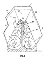
- Fig. 1 shows that, in correspondence with the area where the spirals 9 and 10 converge, driving blades 50 are provided, in order to facilitate the movement of the product towards the upper part of the wagon, in the direction indicated by the arrow 73 in Fig. 4. Further, said blades also improve the unloading of the processed material through the unloading door 100.
- the two groups of counterblades 20 and 21 are positioned inside the wagon, along the line 35 that separates the compartments in which the screw feeders are housed.
- Each group of counterblades is spaced from the vertical walls of the wagon, 23 and 24 respectively.
- said counterblades 20 and 21 stop near the discharge openings provided on the profile of the screw feeders.
- the part of the screw feeder provided with discharge openings does not interact with said counterblades. In this way, the material to be cut and mixed that previously moved among the screw feeder coils converging according to the direction indicated by the arrows 71 and 72 in Fig. 4 in this case can move without being constrained.
- Fig. 4 also shows that, owing to the presence of the discharge openings on the last coil of each spiral belonging to the screw feeder and to the absence of the counterblades, the material is naturally pushed upwards, in the direction indicated by the arrows 73. The material then falls down in correspondence with the walls 23 and 24 of the wagon, according to the direction 230, 240, indicated in Fig. 4.
- the effective cutting of the material is obtained through the rotation of the screw feeders 7 in opposite directions, as indicated by the arrows 80 and 81 in Fig. 6, combined with the fact that the pitches of the screw feeder coils are the same, with aligned profiles, so that the counterblades and the cutters 13 of the screw feeders interact on a plane that is substantially perpendicular to the longitudinal axis of the wagon.
- the rotation of the screw feeders 7 is such as to convey the material to be processed in correspondence of the longitudinal axis the wagon.
- the effective cutting and mixing process inside the wagon provided with the screw feeders object of the invention can be obtained by equipping the wagon with groups of counterblades interrupted, as already explained, in correspondence with the unloading area and in correspondence with the vertical walls of the wagon, owing also to the presence of profiled conveying plates, as shown in Fig. 5 and 6. More precisely, said figures show that the inside container 2 of the wagon, in correspondence with its longitudinal walls and near the compartments where the screw feeders are housed, is provided with profiled conveying plates that are naturally divided on the unloading door side 100 and are indicated by 30 and 31, while on the other side there is a single, continuous profiled conveying plate 32. As it can be better observed in Fig. 6, the profiled conveying plates close the space between each screw feeder 7 and the side walls of the wagon 25 and 26, respectively, so that the material to be processed is forcedly conveyed along the course indicated by the arrows 71 and 72 in Fig. 4.
Landscapes
- Life Sciences & Earth Sciences (AREA)
- Chemical & Material Sciences (AREA)
- Chemical Kinetics & Catalysis (AREA)
- Environmental Sciences (AREA)
- Birds (AREA)
- Animal Husbandry (AREA)
- Biodiversity & Conservation Biology (AREA)
- Apparatuses For Bulk Treatment Of Fruits And Vegetables And Apparatuses For Preparing Feeds (AREA)
- Screw Conveyors (AREA)
- Threshing Machine Elements (AREA)
- Fodder In General (AREA)
- Feeding And Watering For Cattle Raising And Animal Husbandry (AREA)
Claims (6)
- Un chariot découpeur-mélangeur-distributeur pour fourrage et ensilés d'herbe ou de paille comprenant :caractérisé en ce que lesdites spirales de droite et de gauche sont interrompues à environ 180° l'une de l'autre jusqu'à ce qu'elles touchent un plan idéal qui coupe l'axe longitudinal de la vis transporteuse d'une manière essentiellement perpendiculaire et en ce que lesdites ouvertures de déchargement (91, 92, 93 ; 101, 102, 103) sont présentes sur la dernière spire de chaque spirale et ont une distance angulaire d'environ 120° l'une de l'autre.un conteneur (2) équipé d'au moins une ouverture (3) pour l'introduction du matériel à traiter et d'au moins une porte (100) pour le déchargement du matériel traité;au moins deux vis transporteuses pivotantes (7) logées à l'intérieur d'un compartiment (75) ayant une section courbe obtenue sur la partie inférieure (76) du conteneur (2), chacune munie d'au moins une paire de spirales (9,10) sur lesquelles des couteaux périphériques (13) sont fixés, une desdites spirales de chaque paire étant enroulée dans le sens des aiguilles d'une montre (10) et l'autre du même paire dans le sens contraire des aiguilles d'une montre (9), en partant des extrémités de la vis transporteuse et de façon à ce que le matériel traité soit convoyé vers la zone où lesdites spirales de droite et de gauche convergent, ladite spirale étant munie de deux ou plusieurs ouvertures de déchargement obtenues sur son profil, chacune desdites ouvertures de déchargement étant réalisée grâce à la dépose d'une partie de la spirale et étant constituée d'un segment essentiellement radial et d'une partie en forme d'arc qui sont essentiellement orthogonales l'une par rapport à l'autre;contre-lames (20, 21) positionées le long dudit compartiment (75) et interagissant avec lesdites spirales (9, 10) desdites vis transporteuses (7);
- Un chariot selon la revendication 1, où l'extrémité de chaque spirale en face de l'autre spirale est équipée d'au moins une lame de transmission (50) se composant d'une lame fixée à la vis transporteuse et positionée dans une direction longitudinale essentiellement parallèle à la même vis transporteuse.
- Un chariot selon la revendication 1 ou 2, où lesdites vis transporteuses (7) tournent dans des directions opposées (80, 81) de façon à convoyer le matériel à traiter au niveau de l'axe longitudinal du chariot.
- Un chariot selon une quelconque des revendications précédentes muni de deux groupes de contre-lames (20, 21), chaque groupe étant positionné le long la ligne (35) qui sépare les compartiments dans lesquels les vis transporteuses sont logées et étant formé de rebords coupant qui interagissent avec les couteaux (13) d'une des vis transporteuses d'une part et avec les couteaux de l'autre vis transporteuse de l'autre part, chaque groupe de contre-lames étant distancé par rapport aux cloisons verticales du chariot d'une part et étant interrempu avant le commencement des ouvertures de déchargement obtenues sur le profil des vis transporteuses de l'autre part.
- Un chariot selon la revendication 4, où les deux vis transporteuses (7) ont des spires ayant le même pas et avec des profils alignés de façon à ce que les contre-lames (20, 21) et les couteaux (13) de chaque vis transporteuse interagissent sur un plan qui est essentiellement perpendiculaire à l'axe longitudinal du chariot.
- Un chariot selon une quelconque des revendications précédentes, équipé de plaques profilées convoyantes (30, 31, 32) positionnées sur chaque cloison longitudinale (25, 26) du chariot près des compartiments dans lesquels les vis transporteuses (7) sont logées, et ayant une forme telle qu'elles puissent réduire l'espace entre la vis transporteuse et la cloison longitudinale du chariot pour le transfert du matériel à traiter.
Applications Claiming Priority (3)
| Application Number | Priority Date | Filing Date | Title |
|---|---|---|---|
| IT95VI000179A IT1280611B1 (it) | 1995-11-14 | 1995-11-14 | Coclee per carro trincia-miscelatore-distributore per foraggi ed insilati di erba e paglia a profilo perfezionato |
| ITVI950179 | 1995-11-14 | ||
| PCT/EP1996/000934 WO1997017840A1 (fr) | 1995-11-14 | 1996-03-06 | Dispositifs alimentateurs a vis presentant des caracteristiques ameliorees pour remorque coupeuse, melangeuse et alimentatrice, destinee a l'ensilage de fourrage, d'herbe ou de paille |
Publications (2)
| Publication Number | Publication Date |
|---|---|
| EP0862361A1 EP0862361A1 (fr) | 1998-09-09 |
| EP0862361B1 true EP0862361B1 (fr) | 2002-06-19 |
Family
ID=11425889
Family Applications (1)
| Application Number | Title | Priority Date | Filing Date |
|---|---|---|---|
| EP96905862A Expired - Lifetime EP0862361B1 (fr) | 1995-11-14 | 1996-03-06 | Alimenteur a vis presentant du profil ameliore pour remorque coupeuse, melangeuse et alimentatrice, destinee a l'ensilage de fourrage, d'herbe ou de paille |
Country Status (9)
| Country | Link |
|---|---|
| US (1) | US6000649A (fr) |
| EP (1) | EP0862361B1 (fr) |
| AT (1) | ATE219322T1 (fr) |
| AU (1) | AU4945396A (fr) |
| DE (1) | DE69621944T2 (fr) |
| DK (1) | DK0862361T3 (fr) |
| ES (1) | ES2177765T3 (fr) |
| IT (1) | IT1280611B1 (fr) |
| WO (1) | WO1997017840A1 (fr) |
Families Citing this family (24)
| Publication number | Priority date | Publication date | Assignee | Title |
|---|---|---|---|---|
| DE69635066T2 (de) * | 1995-06-06 | 2006-07-20 | Hewlett-Packard Development Co., L.P., Houston | Unterbrechungsschema zum Aktualisieren eines Lokalspeichers |
| CA2181969C (fr) | 1995-12-05 | 2007-07-17 | Charles G. Macku | Asphalteuse avec systeme de transporteur de malaxage des materiaux |
| US6193403B1 (en) * | 1998-03-23 | 2001-02-27 | Leroy C. Nystrom | Bucket mixer attachment for skid steer vehicle |
| FR2785496B1 (fr) * | 1998-11-06 | 2001-01-05 | Grosjean Rene Viticole | Dispositif de convoyage de produits agricoles ou similaires sous forme granulaire et/ou fibreuse |
| US6092750A (en) * | 1999-05-27 | 2000-07-25 | Kooima; John C. | Agricultural mixer auger cutting blade |
| FR2814042B1 (fr) * | 2000-09-15 | 2005-04-29 | Kuhn Audureau Sa | Machine de preparation et de distribution d'aliments pour le betail |
| FR2820952B1 (fr) * | 2001-02-16 | 2003-05-16 | Lucas Sa G | Melangeuse distributrice de produits pour l'alimentation du betail |
| ITVI20010201A1 (it) * | 2001-09-24 | 2003-03-24 | Giuseppe Loppoli | Metodo per la triturazione e la vagliatura di materiali legnosi e trituratore atto a realizzare tale metodo |
| US6923393B1 (en) * | 2002-06-21 | 2005-08-02 | J-Star Industries, Inc. | Horizontal feed mixer and method for using same |
| FR2862188B1 (fr) * | 2003-11-18 | 2011-03-04 | Lucas Sa G | Perfectionnement aux machines melangeuses distributrices de produits |
| ITVI20040226A1 (it) * | 2004-09-24 | 2004-12-24 | Peron Srl Unipersonale | Dispositivo e macchina per lo stoccaggio e o il trasporto di un prodotto per la realizzazione di sottofondi per pavimentazione |
| US7028610B1 (en) * | 2004-12-30 | 2006-04-18 | Ralicki Daniel J | Compacting apparatus |
| US7785034B2 (en) * | 2008-06-26 | 2010-08-31 | Weiler, Inc. | Desegregation system |
| US8556200B2 (en) * | 2010-02-15 | 2013-10-15 | Certainteed Corporation | System, method and apparatus for processing fiber materials |
| US8186611B1 (en) | 2010-03-10 | 2012-05-29 | Kooima Company | Segmented knife assembly with replaceable wear segments |
| RU2498556C1 (ru) * | 2012-03-05 | 2013-11-20 | Федеральное государственное бюджетное образовательное учреждение высшего профессионального образования "Азово-Черноморская государственная агроинженерная академия" (ФГБОУ ВПО АЧГАА) | Измельчитель-смеситель-раздатчик кормов |
| BE1022657B1 (nl) * | 2014-11-21 | 2016-06-28 | Eliet Nv | Afvoerinrichting voor versnipperd organisch materiaal |
| US20160207049A1 (en) * | 2015-01-21 | 2016-07-21 | Mitchell Ellis Products, Inc. | Apparatus and method for decompressing blocks of compressed particulate material |
| ITUB20152702A1 (it) * | 2015-07-31 | 2017-01-31 | Off Mec Forasacco S R L | Dispositivo di fresatura per macchine agricole |
| USD869789S1 (en) * | 2017-04-19 | 2019-12-10 | Rotecna, S.A. | Machine for processing animal feed |
| CA3085963A1 (fr) * | 2017-12-22 | 2019-06-27 | Bradken Resources Pty Limited | Chemise de broyeur |
| RU2705334C1 (ru) * | 2019-03-13 | 2019-11-06 | Федеральное государственное бюджетное образовательное учреждение высшего образования "Тамбовский государственный технический университет" (ФГБОУ ВО "ТГТУ") | Смеситель для сыпучих кормов |
| US11044852B2 (en) | 2019-05-21 | 2021-06-29 | Kooima Ag, Inc. | Agricultural knife with primary and secondary serrations |
| DE102022121143A1 (de) | 2022-08-22 | 2024-02-22 | Trioliet B. V. | Vorrichtung zum Zerkleinern von faserförmigen Pflanzenmaterial |
Family Cites Families (13)
| Publication number | Priority date | Publication date | Assignee | Title |
|---|---|---|---|---|
| DE3528638C2 (de) * | 1985-08-09 | 1997-04-30 | Claas Ohg | Vorrichtung zur Herstellung von Kraftfutter |
| IT215694Z2 (it) * | 1988-07-29 | 1990-10-24 | Seko Spa | Carro trincia miscelatore distributore perfezionato particolarmente per la sfaldatura trinciatura miscelazione e distribuzione di balle cilindriche prismatiche giganti di foraggio e paglia o insilati di erba. |
| IT217375Z2 (it) * | 1989-03-03 | 1991-12-04 | Seko Spa | Perfezionamenti ad un carro per la sfaldatura, trinciatura, miscelazione e distribuzione di balle cilindriche e/o prismatiche giganti di foraggio e paglia o insilati di erba. |
| IT1253105B (it) * | 1991-07-02 | 1995-07-10 | Seko Spa | Carro trincia-miscelatore-distributore perfezionato per foraggi e insilati di erba o paglia. |
| US5199638A (en) * | 1992-03-23 | 1993-04-06 | Allied Products Corporation | Dual auger manure spreader having controlled beater feed |
| DE4239632A1 (de) * | 1992-11-26 | 1994-06-01 | Voelk Maschinenbau Gmbh | Rundballenhäcksler mit zwei Auswurf-Versionen |
| US5439182A (en) * | 1992-12-03 | 1995-08-08 | Sioux Automation Center, Inc. | Equipment/apparatus with one horizontal auger for cutting up and mixing of fibrous products used for the preparation of animal feed |
| US5395286A (en) * | 1992-12-03 | 1995-03-07 | Sioux Automation Center, Inc. | Apparatus for cutting and mixing fibrous products |
| IT1270579B (it) * | 1993-02-26 | 1997-05-06 | Seko Spa | Carro trincia-miscelatore-distributore per foraggi ed insilati di erba o paglia con coclee a profilo centrale perfezionato |
| US5433577A (en) * | 1994-05-11 | 1995-07-18 | Magnificent Machinery, Inc. | Refuse bag opener |
| IT1268994B1 (it) * | 1994-08-31 | 1997-03-18 | Zago Srl | Carro perfezionato per sfaldatura, trinciatura, miscelazione e distribuzione di balle cilindriche e/o prismatiche di foraggio e |
| IT1280519B1 (it) * | 1995-06-13 | 1998-01-22 | Seko Spa | Trincia-miscelatore per il recupero di residui verdi con nastro trasportatore di tipo perfezionato. |
| US5622323A (en) * | 1995-08-10 | 1997-04-22 | Gehl Company | Hay processing system for a mixer feeder |
-
1995
- 1995-11-14 IT IT95VI000179A patent/IT1280611B1/it active IP Right Grant
-
1996
- 1996-03-06 AU AU49453/96A patent/AU4945396A/en not_active Abandoned
- 1996-03-06 WO PCT/EP1996/000934 patent/WO1997017840A1/fr active IP Right Grant
- 1996-03-06 DK DK96905862T patent/DK0862361T3/da active
- 1996-03-06 AT AT96905862T patent/ATE219322T1/de not_active IP Right Cessation
- 1996-03-06 EP EP96905862A patent/EP0862361B1/fr not_active Expired - Lifetime
- 1996-03-06 DE DE69621944T patent/DE69621944T2/de not_active Expired - Fee Related
- 1996-03-06 US US09/068,677 patent/US6000649A/en not_active Expired - Fee Related
- 1996-03-06 ES ES96905862T patent/ES2177765T3/es not_active Expired - Lifetime
Also Published As
| Publication number | Publication date |
|---|---|
| DE69621944D1 (de) | 2002-07-25 |
| EP0862361A1 (fr) | 1998-09-09 |
| ITVI950179A1 (it) | 1996-02-14 |
| WO1997017840A1 (fr) | 1997-05-22 |
| AU4945396A (en) | 1997-06-05 |
| DK0862361T3 (da) | 2002-10-14 |
| IT1280611B1 (it) | 1998-01-23 |
| ITVI950179A0 (it) | 1995-11-14 |
| US6000649A (en) | 1999-12-14 |
| ES2177765T3 (es) | 2002-12-16 |
| ATE219322T1 (de) | 2002-07-15 |
| DE69621944T2 (de) | 2003-02-27 |
Similar Documents
| Publication | Publication Date | Title |
|---|---|---|
| EP0862361B1 (fr) | Alimenteur a vis presentant du profil ameliore pour remorque coupeuse, melangeuse et alimentatrice, destinee a l'ensilage de fourrage, d'herbe ou de paille | |
| US5443588A (en) | Cutter-mixer-feeder wagon with centrally improved screw profile | |
| US5622323A (en) | Hay processing system for a mixer feeder | |
| US5356054A (en) | Wagon with cutting, mixing and dispensing functions for fodder and grass or straw materials stored in silos | |
| US6328465B1 (en) | Vertical feed mixer with auger having center post with sloped top | |
| EP0352670A2 (fr) | Machine déchiqueteuse-mélangeuse-distributrice, en particulier de balles de fourrage, de foin et d'herbe cylindriques et prismatiques | |
| US4480927A (en) | Mixing apparatus and auger therefor | |
| WO1997017841A1 (fr) | Remorque de coupe, de melange et d'alimentation, servant a l'ensilage de fourrage, d'herbe ou de paille et pourvue d'une plateau profile servant a acheminer la matiere a traiter | |
| EP0833558B1 (fr) | Dispositif de melange et de distribution | |
| EP0793911B1 (fr) | Benne mélangeuse distributrice et épandeuse de paille pour litière | |
| US5358187A (en) | Methods of and apparatus for producing improved bedding materials from scrap newspaper | |
| US6203185B1 (en) | Feed mixer having third auger and method for using | |
| EP0385353A2 (fr) | Chariot pour déchiqueter, mélanger et distribuer des balles de fourrage, de pouille ou similaires | |
| WO2010029525A1 (fr) | Appareil mélangeur-distributeur | |
| US6273350B1 (en) | Material handling apparatus | |
| GB2139079A (en) | Agricultural feeder | |
| EP0405313B1 (fr) | Dispositif de désileusement et de transport | |
| AU648857C (en) | Improved wagon with cutting, mixing and dispensing functions for fodder and grass or straw materials stored in silos | |
| WO1996008963A1 (fr) | Appareil servant a melanger et a distribuer une matiere | |
| EP1513607A1 (fr) | Tariere dotee d'un bord incline vers l'avant | |
| IE20090681U1 (en) | Mixer feeder apparatus | |
| IES66917B2 (en) | Apparatus for mixing and dispensing material | |
| GB2345865A (en) | Rotary mixing apparatus with radial arms having radially offset mixing blades |
Legal Events
| Date | Code | Title | Description |
|---|---|---|---|
| PUAI | Public reference made under article 153(3) epc to a published international application that has entered the european phase |
Free format text: ORIGINAL CODE: 0009012 |
|
| 17P | Request for examination filed |
Effective date: 19980612 |
|
| AK | Designated contracting states |
Kind code of ref document: A1 Designated state(s): AT BE CH DE DK ES FI FR GB GR IE IT LI LU MC NL PT SE |
|
| 17Q | First examination report despatched |
Effective date: 20000509 |
|
| GRAG | Despatch of communication of intention to grant |
Free format text: ORIGINAL CODE: EPIDOS AGRA |
|
| GRAG | Despatch of communication of intention to grant |
Free format text: ORIGINAL CODE: EPIDOS AGRA |
|
| GRAH | Despatch of communication of intention to grant a patent |
Free format text: ORIGINAL CODE: EPIDOS IGRA |
|
| GRAH | Despatch of communication of intention to grant a patent |
Free format text: ORIGINAL CODE: EPIDOS IGRA |
|
| GRAA | (expected) grant |
Free format text: ORIGINAL CODE: 0009210 |
|
| AK | Designated contracting states |
Kind code of ref document: B1 Designated state(s): AT BE CH DE DK ES FI FR GB GR IE IT LI LU MC NL PT SE |
|
| PG25 | Lapsed in a contracting state [announced via postgrant information from national office to epo] |
Ref country code: LI Free format text: LAPSE BECAUSE OF FAILURE TO SUBMIT A TRANSLATION OF THE DESCRIPTION OR TO PAY THE FEE WITHIN THE PRESCRIBED TIME-LIMIT Effective date: 20020619 Ref country code: GR Free format text: LAPSE BECAUSE OF FAILURE TO SUBMIT A TRANSLATION OF THE DESCRIPTION OR TO PAY THE FEE WITHIN THE PRESCRIBED TIME-LIMIT Effective date: 20020619 Ref country code: CH Free format text: LAPSE BECAUSE OF FAILURE TO SUBMIT A TRANSLATION OF THE DESCRIPTION OR TO PAY THE FEE WITHIN THE PRESCRIBED TIME-LIMIT Effective date: 20020619 Ref country code: BE Free format text: LAPSE BECAUSE OF FAILURE TO SUBMIT A TRANSLATION OF THE DESCRIPTION OR TO PAY THE FEE WITHIN THE PRESCRIBED TIME-LIMIT Effective date: 20020619 Ref country code: AT Free format text: LAPSE BECAUSE OF FAILURE TO SUBMIT A TRANSLATION OF THE DESCRIPTION OR TO PAY THE FEE WITHIN THE PRESCRIBED TIME-LIMIT Effective date: 20020619 |
|
| REF | Corresponds to: |
Ref document number: 219322 Country of ref document: AT Date of ref document: 20020715 Kind code of ref document: T |
|
| REG | Reference to a national code |
Ref country code: GB Ref legal event code: FG4D |
|
| REG | Reference to a national code |
Ref country code: CH Ref legal event code: EP |
|
| REG | Reference to a national code |
Ref country code: IE Ref legal event code: FG4D |
|
| REF | Corresponds to: |
Ref document number: 69621944 Country of ref document: DE Date of ref document: 20020725 |
|
| PG25 | Lapsed in a contracting state [announced via postgrant information from national office to epo] |
Ref country code: SE Free format text: LAPSE BECAUSE OF FAILURE TO SUBMIT A TRANSLATION OF THE DESCRIPTION OR TO PAY THE FEE WITHIN THE PRESCRIBED TIME-LIMIT Effective date: 20020919 |
|
| PG25 | Lapsed in a contracting state [announced via postgrant information from national office to epo] |
Ref country code: PT Free format text: LAPSE BECAUSE OF FAILURE TO SUBMIT A TRANSLATION OF THE DESCRIPTION OR TO PAY THE FEE WITHIN THE PRESCRIBED TIME-LIMIT Effective date: 20020923 |
|
| REG | Reference to a national code |
Ref country code: DK Ref legal event code: T3 |
|
| ET | Fr: translation filed | ||
| REG | Reference to a national code |
Ref country code: ES Ref legal event code: FG2A Ref document number: 2177765 Country of ref document: ES Kind code of ref document: T3 |
|
| REG | Reference to a national code |
Ref country code: CH Ref legal event code: PL |
|
| PG25 | Lapsed in a contracting state [announced via postgrant information from national office to epo] |
Ref country code: LU Free format text: LAPSE BECAUSE OF NON-PAYMENT OF DUE FEES Effective date: 20030306 Ref country code: IE Free format text: LAPSE BECAUSE OF NON-PAYMENT OF DUE FEES Effective date: 20030306 |
|
| PG25 | Lapsed in a contracting state [announced via postgrant information from national office to epo] |
Ref country code: MC Free format text: LAPSE BECAUSE OF NON-PAYMENT OF DUE FEES Effective date: 20030331 |
|
| PLBE | No opposition filed within time limit |
Free format text: ORIGINAL CODE: 0009261 |
|
| STAA | Information on the status of an ep patent application or granted ep patent |
Free format text: STATUS: NO OPPOSITION FILED WITHIN TIME LIMIT |
|
| 26N | No opposition filed |
Effective date: 20030320 |
|
| REG | Reference to a national code |
Ref country code: IE Ref legal event code: MM4A |
|
| PGFP | Annual fee paid to national office [announced via postgrant information from national office to epo] |
Ref country code: GB Payment date: 20050302 Year of fee payment: 10 |
|
| PGFP | Annual fee paid to national office [announced via postgrant information from national office to epo] |
Ref country code: NL Payment date: 20050303 Year of fee payment: 10 |
|
| PGFP | Annual fee paid to national office [announced via postgrant information from national office to epo] |
Ref country code: DE Payment date: 20050304 Year of fee payment: 10 |
|
| PGFP | Annual fee paid to national office [announced via postgrant information from national office to epo] |
Ref country code: FR Payment date: 20050308 Year of fee payment: 10 |
|
| PGFP | Annual fee paid to national office [announced via postgrant information from national office to epo] |
Ref country code: FI Payment date: 20050314 Year of fee payment: 10 Ref country code: DK Payment date: 20050314 Year of fee payment: 10 |
|
| PGFP | Annual fee paid to national office [announced via postgrant information from national office to epo] |
Ref country code: ES Payment date: 20050425 Year of fee payment: 10 |
|
| PG25 | Lapsed in a contracting state [announced via postgrant information from national office to epo] |
Ref country code: GB Free format text: LAPSE BECAUSE OF NON-PAYMENT OF DUE FEES Effective date: 20060306 Ref country code: FI Free format text: LAPSE BECAUSE OF NON-PAYMENT OF DUE FEES Effective date: 20060306 |
|
| PG25 | Lapsed in a contracting state [announced via postgrant information from national office to epo] |
Ref country code: ES Free format text: LAPSE BECAUSE OF NON-PAYMENT OF DUE FEES Effective date: 20060307 |
|
| PG25 | Lapsed in a contracting state [announced via postgrant information from national office to epo] |
Ref country code: DK Free format text: LAPSE BECAUSE OF NON-PAYMENT OF DUE FEES Effective date: 20060331 |
|
| PGFP | Annual fee paid to national office [announced via postgrant information from national office to epo] |
Ref country code: IT Payment date: 20060331 Year of fee payment: 11 |
|
| PG25 | Lapsed in a contracting state [announced via postgrant information from national office to epo] |
Ref country code: NL Free format text: LAPSE BECAUSE OF NON-PAYMENT OF DUE FEES Effective date: 20061001 |
|
| PG25 | Lapsed in a contracting state [announced via postgrant information from national office to epo] |
Ref country code: DE Free format text: LAPSE BECAUSE OF NON-PAYMENT OF DUE FEES Effective date: 20061003 |
|
| REG | Reference to a national code |
Ref country code: DK Ref legal event code: EBP |
|
| GBPC | Gb: european patent ceased through non-payment of renewal fee |
Effective date: 20060306 |
|
| NLV4 | Nl: lapsed or anulled due to non-payment of the annual fee |
Effective date: 20061001 |
|
| REG | Reference to a national code |
Ref country code: FR Ref legal event code: ST Effective date: 20061130 |
|
| REG | Reference to a national code |
Ref country code: ES Ref legal event code: FD2A Effective date: 20060307 |
|
| PG25 | Lapsed in a contracting state [announced via postgrant information from national office to epo] |
Ref country code: FR Free format text: LAPSE BECAUSE OF NON-PAYMENT OF DUE FEES Effective date: 20060331 |
|
| PG25 | Lapsed in a contracting state [announced via postgrant information from national office to epo] |
Ref country code: IT Free format text: LAPSE BECAUSE OF NON-PAYMENT OF DUE FEES Effective date: 20070306 |