[Technical Field]
The present invention relates to a display device, and
specifically to a display device using a liquid crystal as
variable transmission polarization axis means. Particularly,
the present invention relates to a so-called transflective
liquid crystal display device functioning as a transmissive
liquid crystal display device when a light source is turned
on and functioning as a reflective liquid crystal display
device when the light source is turned off. Also the
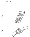
present invention relates to electronic apparatus comprising
the display device as a display unit, such as a watch, an
electronic handbook, a personal computer, and the like.
[Background Art]
A conventional liquid crystal display device comprising
a variable transmission polarization axis optical element
2605 in which the polarization axis of a liquid crystal
is variable, such as a TN (Twisted Nematic) liquid crystal,
STN (Super-Twisted Nematic) crystal, or the like, has a
structure in which the variable transmission polarization
axis optical element 2605 is sandwiched between two
polarizers 2601 and 2606, as shown in Fig. 26. Therefore,
the conventional liquid crystal display device has a low
efficiency of light utilization, and particularly, a
reflective type has a problem with dark display.
[Disclosure of the Invention]
Accordingly, an object of the present invention is to
provide a display device using a variable transmission
polarization axis optical element in which the display
device is capable of obtaining bright display.
Also, in a conventional transflective liquid crystal
display device, an Al reflecting plate is formed thin, or an
opening is provided, thereby decreasing reflectance at
reflective display. As to say, in a transflective type,
brightness at the reflective display is sacrificed.
Accordingly, another object of the present invention is
to provide a transflective liquid crystal display device
with bright reflective display comprising a light source
provided on the back of a liquid crystal display device so
as to permit not only reflective display by external light
but also display by transmitted light from the light source
provided on the back.
In the transflective liquid crystal display device,
when external light is incident on the display device with
the light source turned on due to positive-negative reversal,
display is sometimes hard to see.
Accordingly, a further object of the present invention
is to provide a display device in which display is not hard
to see in case of positive-negative reversal.
In accordance with the present invention, a display
device comprises variable transmission polarization axis
means having a variable transmission polarization axis,
first and second polarized light separating means, disposed
on both side of the variable transmission polarization axis
means, sandwiching thereof , and a light source disposed
opposite to the variable transmission polarization axis
means with respect to the second polarized light separating
means; wherein the first polarized light separating means is
polarized light separating means in which of light incident
on a first side of the first polarized light separating
means, a linearly polarized light component in a first
predetermined direction is transmitted as linearly polarized
light in the first predetermined direction to a second side
opposite to the first side; of light incident on the first
side of the first polarized light separating means, a
linearly polarized light component in a second direction
different from the first predetermined direction is not
transmitted to the second side; of light incident on the
second side of the first polarized light separating means, a
linearly polarized light component in the first direction is
transmitted as linearly polarized light in the first
predetermined direction to the first side; and of light
incident on the second side of the first polarized light
separating means, a linearly polarized light component in
the second direction is not transmitted to the first side;
the second polarized light separating means is polarized
light separating means in which of light incident on the
variable transmission polarization axis means side, a
linearly polarized light component in a third predetermined
direction is transmitted to the light source side, and a
linearly polarized light component in a fourth predetermined
direction different from the third predetermined direction
is reflected to the variable transmission polarization axis
means side; and for light incident from the light source
side, linearly polarized light in the third predetermined
direction can be emitted to the variable transmission
polarization axis means side.
In this display device of the present invention, for
light incident from the outside of the first polarized light
separating means, two display states, i.e., a first display
state created by the light reflected from the second
polarized light separating means and a second display state
where the light transmitted through the second polarized
light separating means is absorbed by the light source side,
are obtained according to the state of the transmission
polarization axis of the variable transmission polarization
axis means, to operate the display device as a reflective
display device. The first display state is a display state
created by the light reflected from the second polarized
light separating means and thus produces bright display.
For light from the light source, two display states,
i.e., a third display state created by the light transmitted
through the first polarized light separating means, and a
fourth display state where no light is transmitted through
the first polarized light separating means, are obtained
according to the state of the transmission polarization axis
of the variable transmission polarization axis means, to
obtain transmissive display.
The second polarized light separating means is
preferably polarized light separating means in which for
light over the substantially whole wavelength range of the
visible light region, of light incident on the variable
transmission polarization axis means side, a linearly
polarized light component in the third predetermined
direction is transmitted to the light source side, and a
linearly polarized light component in the fourth
predetermined direction different from the third
predetermined direction is reflect to the variable
transmission polarization axis means side; and for light
incident on the light source side which is light over the
substantially whole wavelength range of the visible light
region, linearly polarized light in the third predetermined
direction can be emitted to the variable transmission
polarization axis means side.
As a result, the first to fourth display states are
obtained for light over the substantially whole wavelength
range of the visible light region, and transparent or white
display can be obtained in the first and third display
states.
The second polarized light separating means is
preferably polarized light separating means in which of
light incident on the variable transmission polarization
axis means side, a linearly polarized light component in the
third predetermined direction is transmitted as linearly
polarized light in the third predetermined direction to the
optical element side. The second polarized light separating
means is preferably polarized light separating means
comprising films laminated in a plurality of layers in which
the refractive indexes of the plurality of layers are the
same between each adjacent layer in the third predetermined
direction, and different in the fourth predetermined
direction.
The first polarized light separating means preferably
comprises a polarizer.
The variable transmission polarization axis means
preferably comprises a liquid crystal panel, particularly a
TN liquid crystal panel, an STN liquid crystal panel, an F-STN
liquid crystal panel or an ECB liquid crystal panel.
Specifically, the STN liquid crystal panel is an STN liquid
crystal panel using a color compensation optical anisotropic
material, such as an F-STN (Film compensated Super-Twisted
Nematic) liquid crystal panel, or an STN liquid crystal
panel positively using the birefringenceof a liquid crystal
without using a color compensation optical anisotropic
material.
Preferably, reflection from the surface of the light
source can be suppressed by darkening the surface color of
the light source. Consequently, it is possible to decrease
the quantity of the light transmitted through the optical
element and returned by reflection from the light source,
thereby suppressing a decrease in contrast.
Preferably, an optical element is further provided
between the second polarized light separating means and the
light source, which can absorbs light from the second
polarized light separating means side, and transmit light
from the light source to the second polarized light
separating means side.
By providing such an optical element, for light
incident from the outside of the first polarized light
separating means, it is possible to obtain the two display
states, which are the first display state created by the
light reflected from the second polarized light separating
means and the second display state where the light
transmitted through the second polarized light separating
means is absorbed by the light source and the optical
element in accordance with the state of the transmission
polarization axis of the variable transmission polarization
axis means, and thereby a reflective display can be
obtained. In the second display state, light is absorbed by
not only the light source but also the optical element, to
cause a darker display.
For light from the light source, the two display states,
i.e., the third display state created by the light
transmitted through the first polarized light separating
means, and the fourth display state where no light is
transmitted through the first polarized light separating
means, are obtained to realize transmissive display.
The optical element is preferably an optical element
which absorbs light over the substantially whole wavelength
range of the visible region, and more preferably is a
black absorber.
The optical element may has openings. By providing
such openings, light from the light source can be
transmitted to the second polarized light separating means
side through the openings.
In reflective display where external light is incident
on the display device of the present invention, the two
display states, i.e., the first display state created by the
light reflected from the second polarized light separating
means, and the second display state where light transmitted
through the second polarized light separating means is
absorbed by the optical element, are obtained, as described
above. However, since the optical element is an optical
element capable of absorbing light from the second polarized
light separating means side and of transmitting light from
the light source to the second polarized light separating
means side, in the second display state, depending on the
structure of the optical elements, light is not completely
absorbed by the optical element, with some light transmitted
through the optical element, reflected by the light source
or the like, and again transmitted through the optical
element to return the variable transmission polarization
axis means side, causing a decrease in contrast.
Therefore, where the optical element has a plurality of
openings, preferably, the quantity of the light transmitted
through the optical element and returned through the optical
element can be decreased by limiting the ratio of the
openings to the optical element, thereby suppressing a
decrease in contrast. The area ratio of the openings to the
optical element is preferably 5 to 30%.
Preferably, the quantity of the light transmitted
through the optical element and returned by reflection by
the light source can also be decreased by setting the
distance between the optical element and the light source to
be larger than the diameter of the openings, thereby
suppressing a decrease in contrast.
The optical element may comprise a light absorber in a
gray trancelucence state so as to permit absorption of light
from the second polarized light separating means side, and
transmission of light from the light source to the second
polarized light separating means side. In this case, the
light absorber in a gray translucwnce state preferably has a
transmittance of 10 to 80% to the light over the
substantially whole wavelength range of the visible light
region. The transmittance is more preferably 10 to 30%.
The optical element preferably comprises a polarizer
wherein the transmission axis thereof is deviated from that
of the second polarized light separating means. This
enables absorption of light from the variable transmission
polarization axis means side and transmission of light from
the light source to the variable transmission polarization
axis means side.
The optical element preferably comprises a light
scattering member capable of changing the polarization state
of light incident on the optical element and of emitting
light therefrom. By providing such an optical element, for
light incident from the outside of the first polarized light
separating means, the two display states, i.e., the first
display state created by the light reflected by the second
polarized light separating means, and the second display
state where light transmitted through the second polarized
light separating means cannot be transmitted through a
polarized light separator due to removal of the polarization
state by a scattering plate, are obtained according to the
state of the transmission polarization axis of the variable
transmission polarization axis means, and therefore a
reflective display device can be formed. In the second
display state, light is not only absorbed by the light
source but also scattered by the optical element to obtain
darker display.
For light from the light source, the two display states,
i.e., the third display state created by the light
transmitted through the first polarized light separating
means, and the fourth display state where no light is
transmitted through the first polarized light separating
means, are obtained in accordance with the state of the
transmission polarization axis of the variable transmission
polarization axis means, to obtain transmissive display.
Preferably, means for converging light from the light
source to the front of the display device is further
provided.
When seeing the reflective display obtained by
external light, the display is generally seen at a position
at an angle with the normal to the front of the display
device. This is because if the display is seen from the
direction normal to the front of the display device,
external light incident on the display device is hindered by
the observer, and thus the reflective display becomes dark.
On the other hand, when seeing the display obtained by
transmitted light from the light source, the display is
generally seen from the direction normal to the front of the
display device, and thus the display obtained by transmitted
light from the light source can be bright by providing
means for converging light from the light source to the
front of the display device. As a result, transmissive
display obtained by the light from the light source can
easily be seen in the direction normal to the front of the
display device.
Preferably, light diffusion means is further provided.
This can bring about white display in the first display
state by reflection of external light from the second
polarized light separating means and the third display state
by transmission of light from the light source through the
first polarized light separating means.
The light source may comprise a cold cathode tube
capable of emitting white light, and a light guide plate
capable of emitting white light incident from the cold
cathode tube to the second polarized light separating means
side. In the use of white light, for light from the light
source, the two display states, which are the third display
state created by the light transmitted through the first
polarized light separating means and the fourth display
state where no light is transmitted through the first
polarized light separating means, can be obtained to form
transmissive display, as described above. However, for
example, white display is obtained in the third display
state when the state of the transmission polarization axis
of the variable transmission polarization axis means is on,
and black display is obtained in the fourth display state
when the state of the transmission polarization axis of the
variable transmission polarization axis means is off, in
accordance with the structure of the display device. In
this case, when external light is incident on the first
polarized light separating means side of the display device,
the external light produces black display in the second
display state with the transmission polarization axis of the
variable transmission polarization axis means turned on, and
produces white display in the first display state with the
transmission polarization axis of the variable transmission
polarization axis means turned off.
As a result, in both the on and off states, for example,
when the display obtained by transmitted light from the
light source is white display, gray display is obtained due
to addition of reflective black display by external light,
and when the display obtained by transmitted light from the
light source is black display, gray is also obtained due to
addition of reflective white display by external light,
thereby causing positive-negative reversal and making a
display hard to see.
Therefore, LED capable of emitting light in the
predetermined wavelength region to the second polarized
light separating means side, or an EL element capable of
emitting light in the predetermined wavelength region is
preferably used for coloring light from the light source,
thereby obtaining color display on gray background and
making it easy to see a display obtained by the light from
the light source.
Where LED is used as the light source, the light source
preferably comprises a first LED capable of emitting light
in the first predetermined wavelength range, and a second
LED capable of emitting light in the second predetermined
wavelength range different from the first predetermined
wavelength range. Where an EL element is used as the light
source, the light source preferably comprises a first EL
element capable of emitting light in the third predetermined
wavelength range, and a second EL element capable of
emitting light in the fourth predetermined wavelength range
different from the third predetermined wavelength range.
Preferably, the first and second LED or the first and second
EL elements correspond to respective character display
portions to obtain different display colors in the
respective character display portions, thereby usefully
widening the selection range of design.
Where LED is used as the light source, the light source
preferably comprises the LED capable of emitting light in
the predetermined wavelength region, and a light guide plate
capable of emitting light in the predetermined wavelength
region to the second polarized light separating means side.
In this way, since, after light emitted from the LED is
incident on the light guide plate, the light can be
emitted to the second polarized light separating means side,
the arrangement position of the LED can be relatively freely
determined, thereby widening the range of design and making
uniform light for emitting to the second polarized light
separating means side.
The light guide plate preferably has a first light
guide region where light in the first predetermined
wavelength range is incident from the first LED and emitted
to the second polarized light separating means side, and a
second light guide region where light in the second
predetermined wavelength range is incident from the second
LED and emitted to the second polarized light separating
means side, with light shielding means provided between the
first light guide region and the second light guide region.
By providing such light shielding means, mixing of the first
predetermined wavelength region and the second predetermined
wavelength region is prevented, and thus color purity is
increased.
A colored layer capable of transmitting or reflecting
light in the predetermined wavelength region, and of
absorbing light at wavelengths out of the predetermined
wavelength region may be provided between the light source
and the second polarized light separating means. This
causes light from the light source to be colored and
incident on the second polarized light separating means, and
color display on gray background is thus obtained, thereby
making it easy to see transmissive display with the light
from the light source. In this case, since light from the
light source is colored, a white light source such as a cold
cathode tube may be used as the light source. Of course,
the above-described LED or EL element may be used.
The colored layer preferably has a first colored region
capable of reflecting or transmitting light in the first
predetermined wavelength range, and a second colored region
capable of transmitting or reflecting light in the second
predetermined range different from the first predetermined
wavelength range, and is able to absorb light at
wavelengths out of the first or second predetermined
wavelength range. Preferably, the first and second colored
regions correspond to respective character display portions
to obtain different display colors in the respective
character display portions, thereby widening the range of
selection of design.
More preferably, a translective plate which can
transmit light from the light source to the colored layer
side , reflect light which is incident on the colored layer
from the second polarized light separating means side and is
transmitted through the colored layer, and emit the light to
the colored layer side, is further provided. As the
transflective plate, a mirror reflecting plate having
openings provided therein can be used. In this
configuration, for light incident from the outside of the
first polarized light separating means, the two display
states, which are the first display state created by the
light reflected by the second polarized light separating
means, and the second display state created by the light
transmitted through the second polarized light separating
means and reflected by the colored layer, and light
transmitted through the colored layer and then reflected by
the reflecting plate, are obtained according to the state of
the transmission polarization axis of the variable
transmission polarization axis means, to form a reflective
display device. In the second display state, the purity of
coloris increased due to the presence of the reflecting
plate.
An electronic apparatus of the present invention
comprises the above display device as a display unit.
[Brief Description of the Drawings]
Fig. 1 is a sectional view of a display device in
accordance with a first embodiment of the present invention.
Fig. 2 is a schematic sectional view illustrating the
principle of display of the display device in accordance
with the first embodiment of the present invention.
Fig. 3 is a schematic drawing of the configuration of a
polarized light separator 16 used in an embodiment of the
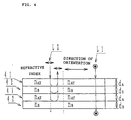
present invention. Fig. 4 is a drawing illustrating the
operation of the polarized light separator 16 shown in Fig.
3.
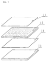
Fig. 5 is a drawing illustrating an example of a light
source used in the present invention.
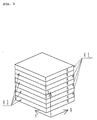
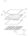
Fig. 6 is a drawing illustrating another example of a
light source used in the present invention.
Fig. 7 is a drawing illustrating still another example
of a light source used in the present invention.
Fig. 8 is a drawing illustrating a further example of a
light source used in the present invention.
Fig. 9 is a drawing illustrating a still further
example of a light source used in the present invention.
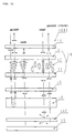
Fig. 10 is a sectional view of a display device in
accordance with a second embodiment of the present invention.
Fig. 11 is a schematic sectional view illustrating the
principle of display of the display device in accordance
with the second embodiment of the present invention.
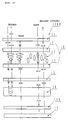
Fig. 12 is a schematic sectional view illustrating a
display device in accordance with a third embodiment of the
present invention.
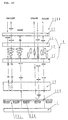
Fig. 13 is a schematic sectional view illustrating a
display device in accordance with a fourth embodiment of the
present invention.
Fig. 14 is a sectional view of a display device in
accordance with a fifth embodiment of the present invention.
Fig. 15 is a schematic sectional view illustrating the
principle of display of the display device in accordance
with the first embodiment of the present invention.
Fig. 16 is a sectional view of a display device in
accordance with a sixth embodiment of the present invention.
Fig. 17 is a schematic sectional view illustrating the
principle of display of the display device in accordance
with the sixth embodiment of the present invention.
Fig. 18 is a drawing illustrating an example of a
colored layer used in the present invention.
Fig. 19 is a drawing illustrating another example of a
colored layer used in the present invention.
Fig. 20 is a sectional view of a display device in
accordance with a seventh embodiment of the present
invention.
Fig. 21 is a schematic sectional view illustrating the
principle of display of the display device in accordance
with the seventh embodiment of the present invention.
Fig. 22 is a sectional view of a display device in
accordance with an eighth embodiment of the present
invention.
Fig. 23 is a schematic sectional view illustrating the
principle of display of the display device in accordance
with the eighth embodiment of the present invention.
Fig. 24 is a drawing showing an example in which a
prism sheet is combined with a display device of the present
invention.
Fig. 25 is a drawing showing examples of electronic
apparatus comprising a display device as a display unit.
Fig. 26 is a drawing showing an example of conventional
display devices.
[Best Mode for Carrying Out the Invention]
Embodiments of the present invention will be described
below with reference to the drawings.
First embodiment
(Basic structure)
Fig. 1 is a sectional view of a display device in
accordance with a first embodiment of the present invention,
and Fig. 2 is a schematic sectional view illustrating the
principle of display of the display device in accordance
with the first embodiment of the present invention.
A display 100 of this embodiment is a display device
with a so-called transflective function which is capable of
not only reflective display using reflection of external
light in a place where external light is present, but also
transmission display using light from a light source in a
place where external light is absent.
First the structure of the display device of this
embodiment is described with reference to Fig. 1. In the
display device 100, a TN liquid crystal panel 10 is used as
a variable transmission polarization axis optical element.
In the TN liquid crystal panel 10, a TN liquid crystal 13 is
held between two glass plates 11 and 12, and a plurality of
character display portions (not shown in the drawing) are
provided to enable character display. On the upper side of
the TN liquid crystal panel 10 is provided a polarizer 14.
On the lower side of the TN liquid crystal panel 10 are
provided a light scattering member 15, a polarized light
separator 16, and a light source 17 in this order. In order
to drive the TN liquid crystal 10, a TAB substrate(not shown
in the drawing) provided with a driver IC is connected to
the TN liquid crystal panel 10 to form the display device.
(Polarized light separator)
Next, the polarized light separator used in this
embodiment is described with reference to Figs. 3 and 4.
Fig. 4 is a schematic drawing showing the configuration of
the polarized light separator 16 used in this embodiment,
and is a drawing illustrating the operation of the polarized
light separator 16 shown in Fig. 3. The polarized light
separator 16 has a structure in which two layers 41 (A
layer) and 42 (B layer) are alternately laminated in a
plurality of layers. In the polarized light separator 16,
although the refractive index (nAX) of the A layers 41 in the
X axis direction is different from the refractive index (nBX)
of the B layers 42 in the X axis direction, the refractive
index (nAY) of the A layers 41 in the Y axis direction is
substantially the same as the refractive index (nBY) of the B
layers 42 in the Y axis direction. Of light incident on the
polarized light separator 16, linearly polarized light in
the Y axis direction is transmitted through the polarized
light separator 16 because the refractive index of the A
layers 41 is substantially the same as the reflective index
of the B layers in the polarized light separator 16. On the
other hand, in the polarized light separator 16, if the
thickness of the A layers 41 in the Z axis direction is tA,
and the thickness of the B layers 41 is tB, the following
equation is satisfied:
tA · nAX + tB · nBX = λ/2
so that of light incident at wavelength λ on the polarized
light separator 16, linearly polarized light in the X axis
direction is reflected by the polarized light separator 16.
Since the thickness of the A layers 41 and the thickness of
the B layers 42 in the Z axis direction varies, of light
incident on the polarized light separator 16 over a wide
range of the visible wavelength region, the polarized light
separator 16 reflects linearly polarized light in the X axis
direction.
In the polarized light separator 16, oriented
polyethylene naphthalate (PET; polyethylene naphthalate) is
used for the A layers 41, and copolyester of naphthalene
dicarboxylic acid and terephthalic acid (coOEN; copolyester
of naphthalene dicarboxylic acid and terephthalic or
isothalic acid) can be used for the B layers 42.
Of course, materials of the polarized light separator
16 used in the present invention are not limited to these
materials, and materials can be appropriately selected.
Such a polarized light separator is disclosed in detail as a
reflective polarizer in Unexamined International Application
(International Application No. WO/95/27819 and WO95/17692).
Although, in this embodiment, the above polarized light
separator is used, besides the polarized light separator, a
separator comprising a cholesteric liquid crystal layer held
between λ/4 plates, a separator using the angle of
polarization (SID 92DIGEST pp. 427-429), a separator using
hologram, and the like have the same function as the above
polarized light separator, and may be used for the display
device of this embodiment.
(Principle of display)
On the assumption that the right half of the display
device 100 is a voltage applied portion, and the left half
thereof is a voltage unapplied portion, the principle of
display with the display device 100 is described below with
reference to Fig. 2.
First, reflective display where external light is
incident on the display device 100 is described.
In the voltage unapplied portion on the left hand side,
when external light is incident on the display device 100,
the external light is changed to linearly polarized light
parallel to the drawing by the polarizer 14, and then the
direction of polarization is rotated for 90° by the TN
liquid crystal 13 to form linearly polarized light
perpendicular to the drawing. The linearly polarized light
perpendicular to the drawing is reflected by the polarized
light separator 16, and then the direction of polarization
is rotated for 90° by the TN liquid crystal 13 to form
linearly polarized light parallel to the drawing, which is
emitted as linearly polarized light parallel to the drawing
from the polarizer 14. With no voltage applied, incident
external light is reflected by the polarized light separator
16, not absorbed thereby, to obtain bright reflective
display. Since the light scattering member 15 is provided
between the polarized light separator 16 and the TN liquid
crystal panel 10, light reflected from the polarized light
separator 16 is changed from a mirror state to a white state.
In the voltage applied portion on the right hand side,
when external light is incident on the display device 100,
the external light is changed to linearly polarized light
parallel to the drawing, and then transmitted through the TN
liquid crystal 13 without changing in the direction of
polarization, and the polarized light separator 16 is also
transmitted without changing in the direction of
polarization to reach the light source 17. Since most of
the light which reaches the light source 17 is transmitted
through the light source or absorbed thereby, the display
becomes dark .
In this way, in reflective display where external light
is incident on the display device 100, in the voltage
unapplied portion, light reflected by the polarized light
separator 16 is transmitted through the light scattering
member 15 to make the display bright , and in the voltage
applied portion, light transmitted through the polarized
light separator 16 is mostly transmitted through or absorbed
by the light source 17 to make the display dark .
With no voltage applied, since external light incident
on the display device 100 is reflected by the polarized
separator 16, not absorbed thereby, bright display is
obtained.
Next, transmissive display with the light from the
light source is described.
In the voltage unapplied portion on the left hand side,
light from the light source 17 is incident on the polarized
light separator 16, and changed to linearly polarized light
parallel to the drawing by the polarized light separator 16.
Then the direction of polarization is rotated for 90° by the
TN liquid crystal 13 to form linearly polarized light
perpendicular to the drawing, which is absorbed by the
polarizer 14, to make the display dark .
In the voltage applied portion on the right hand side,
light from the light source 17 is incident on the polarized
light separator 16, scattered by the light scattering member
15, then transmitted through the TN liquid crystal 13
without changing in the direction of polarization, and also
transmitted through the polarizer 14, to make the display
bright .
In this way, in transmissive display with the light
from the light source 17, in the voltage unapplied portion,
light from the light source 17 is absorbed by the polarizer
14 to make the display dark .In the voltage applied portion,
light from the light source is transmitted through the
polarizer 14 to make the display bright .
Therefore, the display device 100 of this embodiment is
a reflective display device with a so-called transflective
function, which is capable of not only reflective display
using reflection of external light at a place with
external light , but also transmissive display using light
from the light source 17 at a place without external
light .
(Scattering plate)
As the scattering plate used in the display device of
this embodiment, a scattering plate capable of emitting
incident light without removing the state of polarization
to the utmost . Since this scattering plate has the
function to scatter and cloud the light emitted from the
scattering plate , a display device with cloudy display
(white display) is obtained. In contrast, removal of the
scattering plate 15 from the configuration produces a
display device with glossy display. Therefore, the
scattering plate may be selected in accordance with
application of the display device.
(Light source)
Figs. 5 to 9 respectively show display devices using
various light sources in accordance with this embodiment of
the present invention. In this embodiment, any one of the
light sources shown in Figs. 5 to 8 can be used.
The light source used in the display device shown in
Fig. 5 comprises a cold cathode tube 50 as a light source
and a light guide plate 51. As the light guide plate 51, a
light guide plate having the function to absorb light when
the cold cathode tube 50 is turned off is used. Where the
light source shown in Fig. 5 is used for the display device
of this embodiment, display where external light including
visible wavelength components having a plurality of colors
is incident, i.e., reflective display, becomes black display
in the voltage applied portion and becomes white display in
the voltage unapplied portion, respectively. On the other
hand, transmissive display with the light from the light
source becomes display having the color of the light emitted
from the cold cathode tube, i.e., white display, in the
voltage applied portion, and becomes black display in the
voltage unapplied portion.
The light source used for the display device shown in
Fig. 6 comprises a LED 60 which emits light at the
wavelength corresponding to red as light source,, and a
light guide plate 61. In use of the light source shown in
Fig. 6 for the display device of this embodiment,
reflective display becomes black display in the voltage
applied portion and becomes white display in the voltage
unapplied portions, respectively. On the other hand,
transmissive display using light from the light source
becomes display having the color of the light emitted from
the LED 60, i.e., red display, in the voltage applied
portion, and becomes black display in the voltage unapplied
portion.
In use of the light source shown in Fig. 5, as
described above, for light from the light source 17, dark
display is obtained in the voltage unapplied portion and
bright display is obtained in the voltage applied portion,
respectively, to form transmissive display. However, in
this case, when external light is incident on the front side
of the display device, bright display is obtained in the
voltage unapplied portion and dark display is obtained in
the voltage applied portion, respectively, due to the
external light. As a result, in both the voltage unapplied
portion and the voltage applied portion, for example, when
display with transmitted light from the light source 17 is
bright display, gray display is obtained due to addition of
reflective dark display by external light, and when display
with transmitted light from the light source 17 is dark
display, gray display is also obtained due to addition of
reflective bright display by external light, to cause so-called
positive-negative reversal and sometimes make display
hard to see.
When the light source shown in Fig. 6 is turned on at
incidence of external light, in the voltage applied portion,
the light emitted from the LED can be seen so as to make
display graynish red , and in the voltage unapplied portion,
the light reflected by the polarized light separator 16 can
be seen so as to make display gray . Therefore, the
display is significantly easy to see as compared with simple
black-and-white display.
The LED 60 which emits light having the wavelength
correspond to red is used in Fig. 6, but LED which emits
light having the wavelength correspond to a color other than
red may be used.
The light source used for the display device shown in
Fig. 7 comprises an EL element 70 as a light source, which
emits light having the wavelength of green. In use of the
light source shown in Fig. 17 for the display device of
this embodiment, reflective display becomes black display
in the voltage applied portion and becomes white display in
the voltage unapplied portion, respectively. On the other
hand, transmissive display by the light from the light
source becomes display having the color of the light emitted
from the EL element 70, i.e., green display, in the voltage
applied portion, and becomes black display in the voltage
unapplied portion. When the light source shown in Fig. 7 is
turned on at incidence of external light, in the voltage
applied portion, the light emitted from the EL element 70
can be seen so as to make display grayish green , and in
the voltage unapplied portion, the external light reflected
by the polarized light separator can be seen so as to make
display gray . The EL element 70 which emits light having
the wavelength of green is used in Fig. 7, but, of course,
an EL element which emits light having the wavelength of a
color other than green may be used.
The light source used for the display device shown in
Fig. 8 comprises as light sources an LED 81 which emits
light having the wavelength of red, and an LED 82 which
emits light having the wavelength of blue, both LEDs being
disposed on the side of a light guide plate 83. The light
guide plate is partitioned by a reflecting plate 84 into
regions corresponding to the LEDs so as not to mix light
having the wavelengths emitted from the respective light
guide plates. The LEDs are arranged so that the emitted
lights correspond to a plurality of character display
portions 85 and 86 formed in the liquid crystal panel. In
use of the light source shown in Fig. 8 for the display
device of this embodiment, reflective display becomes black
display in the voltage applied portion and becomes white
display in the voltage unapplied portion, respectively. On
the other hand, transmissive display with the light from
the light source becomes display having the color of the
light emitted from each of the LEDs in the corresponding
character display portion, i.e., red or blue display, in the
voltage applied portion, and becomes black display in the
voltage unapplied portion. When the light source 8 shown in
Fig. 8 is turned on at incidence of external light, in the
voltage applied portion, the light emitted from each of the
LEDs can be seen to make display graynish red or blue in
each of the character display portions, and in the voltage
unapplied portion, external light reflected by the polarized
light separator can be seen to make display gray . As
shown in Fig. 8, the LED which emits light having the
wavelength of red and the LED which emits light having the
wavelength of blue are used, but, of course, an LED which
emits light having the wavelength of a color other than
these colors may be used, and combination may be
appropriately selected according to application.
The light source used for the display device shown in
Fig. 9 comprises a plurality of LEDs 91 which emit light
having the wavelength of red, and a plurality of LEDs 92
which emit light having the wavelength of blue, with the
LEDs arranged as a group for each of the colors. The light
source shown in Fig. 9 has no light guide plate. Further,
the LED groups are arranged so that the emitted lights
respectively correspond to a plurality of character display
portions formed in the liquid crystal panel. In use of the
light source shown in Fig. 9 for the display device of this
embodiment, reflective display becomes black display in the
voltage applied portion and becomes white display in the
voltage unapplied portion, respectively. On the other hand, a
transmissive display by the light from the light source
becomes display having the color of the light emitted from
each of the LED groups respectively corresponding to the
character display portions, i.e., red or blue display, in
the voltage applied portion, and becomes black display in
the voltage unapplied portion. When the light source shown
in Fig. 9 is turned on at incidence of external light,
light emitted from each of the LED groups can be seen to
make display graynish red or blue in each of the character
display portions in the voltage applied portion, and
external light reflected by the polarized light separator
can be seen to make display gray in the voltage unapplied
portion. The LED 91 which emits light having the red
wavelength and the LED 92 which emits light having the blue
wavelength are used in Fig. 9, but, of course, LED which
emits light having the wavelength of a color other than
these colors may be used, and its combination can be
appropriately selected.
(Second Embodiment)
Fig. 10 is a sectional view of a display device in
accordance with a second embodiment of the present invention,
and Fig. 11 is a schematic sectional view illustrating the
principle of display of the display device in the second
embodiment of the invention.
The display device 1000 of this embodiment is a
reflective display device with a so-called transflective
function, which is capable of not only reflective display
using reflection of external light at a place with
external light , but also transmissive display using light
from the light source at a place without external light .
(Basic structure)
First the structure of the display device of this
embodiment is descried below with reference to Fig. 10. In
the display device 1000, a TN liquid crystal panel 10 is
used as a variable transmission polarization axis optical
element. In the TN liquid crystal panel 10, a TN liquid
crystal 13 is held between two glass plates 11 and 12, and a
plurality of character display portions (not shown in the
drawing) are provided to enable character display. On the
upper side of the TN liquid crystal panel 10 is provided a
polarizer 14. On the lower side of the TN liquid crystal
panel 10 are provided a light scattering member 15, a
polarized light separator 101, a light absorber 102, and a
light source 17 in this order. The light absorber 102 is
black and has a plurality of openings 103 at a
predetermined area density. In order to drive the TN liquid
crystal 13, a TAB substrate (not shown in the drawing)
provided with a driver IC is connected to the TN liquid
crystal panel 10 to form the display device.
(Polarized light separator)
The polarized light separator 101 comprises a (1/4) λ
plate 104 and a cholesteric liquid crystal layer 105. The
cholesteric liquid crystal layer 105 is light having the
same wavelength as the pitch of the liquid crystal and
reflects circularly polarized light with the same direction
of rotation as the liquid crystal, transmitting other light.
Therefore, for example, when a cholesteric liquid crystal
having a pitch of 5000 angstroms and counterclockwise
rotation is used for the cholesteric liquid crystal layer
105, a device is obtained in which left-handed circularly
polarized light having a wavelength of 5000 angstroms is
reflected, and right-handed circularly polarized light and
light having other wavelengths are transmitted. Further, by
using a cholesteric liquid crystal having counterclockwise
rotation and changing the pitch thereof in the cholesteric
liquid crystal over the whole wavelength range of visible
light, an element is obtained in which reflects left-handed
circularly polarized light not only for monochrome
light but also over the whole range of bright color light, ,
and transmits right-handed circularly polarized light . In
this embodiment, a cholesteric liquid crystal having
counterclockwise rotation is used for the cholesteric liquid
crystal layer 105, and the pitch thereof is changed in the
cholesteric liquid crystal over the whole wavelength range
of visible light.
In the polarized light separator 101 comprising
combination of the cholesteric liquid crystal layer 105 and
the (1/4) λ plate 104, when linearly polarized light in the
predetermined first direction is incident on the (1/4) λ
plate 104 side, the light is changed to left-handed
circularly polarized light by the (1/4) λ plate 104,
reflected by the cholesteric liquid crystal layer 105,
changed again to linearly polarized light in the
predetermined first direction by the (1/4) λ plate 104, and
then emitted. When linearly polarized light in the second
direction perpendicular to the first direction is incident,
the light is changed to right-handed circularly polarized
light by the (1/4) λ plate 104, and transmitted through the
cholesteric liquid crystal layer 105. For light incident on
the lower side of the cholesteric liquid crystal layer 105,
linearly polarized light in the second direction is emitted
upward from the (1/4) λ plate 104.
In this way the polarized light separator 101
comprising combination of the cholesteric liquid crystal
layer 105 and the (1/4) λ plate 104 is polarized light
separating means in which of light incident from the (1/4) λ
plate 104 side,a linearly polarized light component in the
predetermined second direction is transmitted, and linearly
polarized light component in the first direction
perpendicular to the predetermined second direction is
reflected, and for light incident on the cholesteric liquid
crystal layer 105 side, linearly polarized light in the
second direction can be emitted to the (1/4) λ plate 104
side. Besides the polarized light separator 101 comprising
combination of the cholesteric liquid crystal layer 105 and
the (1/4) λ plate 104, polarized light separators having the
above function include a separator comprising films
laminated in multilayers (USP 4,974,219), a separator for
separating into reflective polarized light and transmissive
polarized light using Brewster angle (SID 92DIGEST pp.
427-429), a separator using hologram, and the polarized
light separator described above in the first embodiment with
reference to Figs. 3 and 4, i.e., the separator disclosed in
Unexamined International Applications (International
Application Nos. WO95/27819 and WO95/17692).
(Principle of display)
On the assumption that the right half of the display
device 1000 is a voltage applied portion, and the left half
thereof is a voltage unapplied portion, the principle of
display by the display device 1000 is described.
First, reflective display where external light is
incident on the display device 1000 is described.
In the voltage unapplied portion on the left hand side,
when external light is incident on the display device 1000,
the external light is changed to linearly polarized light
parallel to the drawing by the polarizer 14, and then the
direction of polarization is rotated for 90° by the TN
liquid crystal 13 to form linearly polarized light
perpendicular to the drawing. The linearly polarized light
perpendicular to the drawing is changed to left-handed
circularly polarized light by the (1/4) λ plate 104,
reflected by the cholesteric liquid crystal layer 105, is
again incident on the (1/4) λ plate 104, and changed to
linearly polarized light perpendicular to the drawing by the
(1/4) λ plate 104. Then the direction of polarization is
rotated for 90° by the TN liquid crystal 13 to form linearly
polarized light parallel to the drawing, which is emitted as
linearly polarized light parallel to the drawing from the
polarizer 14. In this way, with no voltage applied, since
incident external light is reflected by the polarized light
separator 101, not absorbed thereby , bright reflective
display can be obtained. Since the light scattering member
15 is provided between the polarized light separator 101 and
the TN liquid crystal panel 10, light reflected by the
polarized light separator 101 is changed from a mirror state
to a bright color state.
In the voltage applied portion on the right hand side,
when external light is incident on the display device 1000,
the external light is changed to linearly polarized light
parallel to the drawing by the polarizer 14, and then
transmitted through the TN liquid crystal 13 without
changing the direction of polarization. The linearly
polarized light is changed to right-handed circularly
polarized light by the (1/4) λ plate 104, and transmitted
through the cholesteric liquid crystal layer 105. The
right-handed circularly polarized light transmitted through
the cholesteric liquid crystal layer 105 is absorbed by the
black light absorber 102 to obtain dark display.
In this way, in reflective display where external light
is incident on the display device 100, in the voltage
unapplied portion, light reflected by the polarized light
separator 101 is transmitted through the light scattering
member 15 to obtain bright display, and in the voltage
applied portion, light transmitted through the polarized
light separator 101 is absorbed by the light absorber 102 to
obtain dark display.
With no voltage applied, since external light incident
on the display device 1000 is reflected by the polarized
separator 101, not absorbed thereby, bright display is
obtained.
Next, transmissive display by the light from the light
source 17 is described.
In the voltage unapplied portion on the left hand side,
light from the light source 17 is incident on the
cholesteric liquid crystal layer 105 of the polarized light
separator 101 through the openings 103 provided in the black
light absorber 102, and only right-handed circularly
polarized light is transmitted through the cholesteric
liquid crystal layer 105, and changed to linearly polarized
light parallel to the drawing by the (1/4) λ plate 104.
Then the direction of polarization is rotated for 90° by the
TN liquid crystal 13 to form linearly polarized light
perpendicular to the drawing, which is absorbed by the
polarizer 14 to obtain dark display.
In the voltage applied portion on the right hand side,
light from the light source 17 is incident on the polarized
light separator 101 and on the cholesteric liquid crystal
layer 105 through the openings 103 provided in the black
light absorber 102, and only right-handed circularly
polarized light is transmitted through the cholesteric
liquid crystal layer 105 and changed to linearly polarized
light parallel to the drawing by the (1/4) λ plate 104. The
lineraly polarized light is transmitted through the light
scattering member 15, through the TN liquid crystal 13
without changing the direction of polarization, and then
through the polarizer 14 to obtain bright display.
In this way, in transmissive display by the light from
the light source 17, in the voltage unapplied portion, light
from the light source 17 is absorbed by the polarizer 14 to
obtain dark display, and in the voltage applied portion,
light from the light source 17 is transmitted through the
polarizer 14 to obtain bright display.
Therefore, the display device 1000 of this embodiment
is a reflective display device with a so-called
transflective function, which is capable of not only bright
reflective display using reflection of external light at a
place with external light , but also transmissive display
using light from the light source 17 at a place with
external light .
(Scattering plate)
As the scattering plate 15 used in the display device
of this embodiment, a scattering plate capable of emitting
incident light without removing the state of polarization
to the utmost is used. Since this scattering plate has the
function to scatter and cloud the light emitted from the
scattering plate , a display device with cloudy display
(white display) is obtained. In contrast, removal of the
scattering plate 15 from the configuration produces a
display device with glossy display. Therefore, the
scattering plate may be selected in accordance with
application of the display device.
(Light absorber)
In this embodiment, in reflective display where
external light is incident on the display device 1000, the
two display states, i.e., bright display by the light
reflected by the polarized light separator 101, and dark
display where light transmitted through the polarized light
separator 101 is absorbed by the light absorber 102, are
obtained, as described above. However, since the light
absorber 102 is a black light absorberto absorb light from
the polarized light separator 101, and has a plurality of
the openings 103 through which light can be transmitted , in
the dark display state, light is not completely absorbed by
the light absorber 102, but some light is transmitted
through the openings 103 of the light absorber 102,
reflected by the light source or the like, again transmitted
through the openings 103 of the light absorber 102, and
returned to the TN liquid crystal panel 10 side, causing a
decrease in contrast.
Therefore, the area ratio of the openings 103 to the
light absorber 102 is preferably limited to decrease the
amount of the light which is transmitted through the
openings 103 of the light absorber 102, reflected by the
light source 17 or the like, and returned through the
openings 103 of the light absorber 102, thereby suppressing
a decrease in contrast.
Although, in this embodiment, a black light absorber
having the plurality of openings 103 is used as the light
absorber 102, a light absorber in a gray translucence state
can also be used for absorbing light from the polarized
light separator 101 side and for transmitting light from the
light source to the polarized light separator 101 side. In
this case, since the light absorber is in a gray
translucence state, the openings need not be provided. As
the light absorber in a gray translucence state, light
diffusion film D202 (produced by Tsujimoto Denki Seisakusho)
or the like can be used.
Although the black light absorber having the plurality
of openings 103 is used as the light absorber 102, a
polarizer having an absorption axis shifted from that of the
polarized light separator 101 can be used in place of the
light absorber 102. In this way , with the polarized light
separator 101 and the polarizer having an absorption axis
shifted from that of the polarized light separator 101,
light from the TN liquid crystal panel 10 side can be
absorbed and light from the light source 17 can be
transmitted to the TN liquid crystal panel 10 side.
(Light source)
In the display device of this embodiment, the various light
sources shown in Figs. 1 to 9 and described in the first
embodiment can be used. The operation and advantages are
the same as the first embodiment, and thus description
thereof is omitted.
Third Embodiment
(Basic structure)
Fig. 12 is a schematic sectional view illustrating a
display device in accordance with a third embodiment of the
invention.
In the second embodiment, the polarized light separator
101 comprising the (1/4) λ plate 104 and the cholesteric
liquid crystal layer 105 is used. This embodiment is
different from the second embodiment in that a polarized
light separator 121 comprising a (1/4) λ plate 104, a
cholesteric liquid crystal layer 105, and a (1/4) λ plate
120 is used in place of the polarized light separator 101,
but other points are the same as the second embodiment.
(Polarized light separator)
In the polarized light separator 121 comprising the
(1/4) λ plates 104 and 120 on both sides of the cholesteric
liquid crystal layer 105, when linearly polarized light in
the predetermined first direction is incident on the (1/4) λ
plate 104 side, the light is changed to left-handed
circularly polarized light by the (1/4) λ plate 104,
reflected by the cholesteric liquid crystal layer 105,
changed again to linearly polarized light in the
predetermined first direction by the (1/4) λ plate 104, and
then emitted. When linearly polarized light in the second
direction perpendicular to the first direction is incident,
the light is changed to right-handed circularly polarized
light by the (1/4) λ plate 104, transmitted through the
cholesteric liquid crystal layer 105, again changed to
linearly polarized light in the second direction by the
(1/4) λ plate 120, and then emitted. For light incident on
the lower side of the (1/4) λ plate 146, linearly polarized
light in the second direction is emitted upward from the
(1/4) λ plate 104.
In this way, the polarized light separator 121
comprising a combination of the cholesteric liquid crystal
layer 105 and the (1/4) λ plates 104 and 120 is polarized
light separating means in which of light incident on the
(1/4) λ plate 104 side, a linearly polarized light component
in the predetermined second direction is transmitted, and a
linearly polarized light component in the first direction
perpendicular to the predetermined second direction is
reflected, and for light incident on the (1/4) λ plate 120
side, linearly polarized light in the second direction can
be emitted to the (1/4) λ plate 104 side. Besides the
polarized light separator 121 comprising a combination of
the cholesteric liquid crystal layer 105 and the (1/4) λ
plates 104 and 120, polarized light separators having the
above function include a separator comprising films
laminated in multilayers (USP 4,974,219), a separator for
separating into reflected polarized light and transmitted
polarized light by using Brewster angle (SID 92DIGEST pp.
427-429), a separator using hologram, and the polarized
light separator described above in the first embodiment with
reference to Figs. 3 and 4, i.e., the separator disclosed as
a reflective polarizer in Unexamined International
Applications (International Application Nos. WO95/27819 and
WO95/17692).
(Principle of display)
On the assumption that the right half of the display
device 1200 is a voltage applied portion, and the left half
thereof is a voltage unapplied portion, the principle of
display by the display device 1200 is described.
First, reflective display where external light is
incident on the display device 1200 is described.
The function of the voltage unapplied portion on the
left hand side is the same as the voltage unapplied portion
of the first embodiment. Namely, when external light is
incident on the display device 1200, the external light is
changed to linearly polarized light parallel to the drawing
by the polarizer 14, and then the direction of polarization
is rotated for 90° by the TN liquid crystal 13 to form
linearly polarized light perpendicular to the drawing. The
linearly polarized light perpendicular to the drawing is
changed to left-handed circularly polarized light by the
(1/4) λ plate 104, reflected by the cholesteric liquid
crystal layer 105to be incident again on the (1/4) λ plate
104, and changed to linearly polarized light perpendicular
to the drawing by the (1/4) λ plate 104. Then the direction
of polarization is rotated for 90° by the TN liquid crystal
13 to form linearly polarized light parallel to the drawing,
which is emitted as linearly polarized light parallel to the
drawing from the polarizer 14. In this way, with no voltage
applied, incident external light is reflected by the
polarized light separator 121, not absorbed thereby, to
obtain bright reflective display. Since the light
scattering member 15 is provided between the (1/4) λ plate
104 and the TN liquid crystal panel 10, light reflected by
the polarized light separator 101 is changed from a mirror
state to a white state.
In the voltage applied portion on the right hand side,
when external light is incident on the display device 1200,
the external light is changed to linearly polarized light
parallel to the drawing by the polarizer 14, and then
transmitted through the TN liquid crystal 13 without
changing the direction of polarization. The linearly
polarized light is changed to right-handed circularly
polarized light by the (1/4) λ plate 104, and transmitted
through the cholesteric liquid crystal layer 105. The
right-handed circularly polarized light transmitted through
the cholesteric liquid crystal layer 105 is changed to
linearly polarized light parallel to the drawing by the
(1/4) λ plate 120, and then absorbed by the black light
absorber 102 to obtain dark display.
In this way, in reflective display where external light
is incident on the display device 1200, in the voltage
unapplied portion, light is reflected by the polarized light
separator 121 to obtain bright display, and in the voltage
applied portion, light transmitted through the polarized
light separator 121 is absorbed by the light absorber 102 to
obtain dark display.
With no voltage applied, since external light incident
on the display device 1200 is reflected by the polarized
separator 121, not absorbed thereby, bright display is
obtained.
Next, transmissive display with the light from the
light source 17 is described.
In the voltage unapplied portion on the left hand side,
light from the light source 17 is incident on the (1/4) λ
plate 120 of the polarized light separator 121 through the
openings 103 provided in the black light absorber 102,
transmitted through the (1/4) λ plate 120 to be incident
on the cholesteric liquid crystal layer 105, in which right-handed
circularly polarized light is transmitted, and left-handed
circularly polarized light is reflected. The
transmitted circularly polarized light is changed to
linearly polarized light parallel to the drawing by the
(1/4) λ plate 104. Then the direction of polarization is
rotated for 90° by the TN liquid crystal 13 to form linearly
polarized light perpendicular to the drawing, which is
absorbed by the polarizer 14 to obtain dark display.
In the voltage applied portion on the right hand side,
light from the light source 17 is incident on the (1/4) λ
plate 120 of the polarized light separator 121 through the
openings 103 provided in the black light absorber 102, and
only right-handed circularly polarized light of the light
incident on the cholesteric liquid crystal layer 105 is
transmitted therethrough and changed to linearly polarized
light parallel to the drawing by the (1/4) λ plate 104. The
linearly polarized light is transmitted through the light
scattering member 15, through the TN liquid crystal 13
without changing the direction of polarization, and then
through the polarizer 14 to obtain bright display.
In this way, in transmissive display with the light
from the light source 17, in the voltage unapplied portion,
light from the light source 17 is absorbed by the polarizer
14 to obtain dark display, and in the voltage applied
portion, light from the light source 17 is transmitted
through the polarizer 14 to obtain bright display.
Therefore, the display device 1200 of this embodiment
is a reflective display device with a so-called
transflective function, which is capable of not only bright
reflective display using reflection of external light at a
place with external , but also transmissive display using
light from the light source 17 at a place without external
light .
(Scattering plate)
As the scattering plate used in the display device of
this embodiment, a scattering plate capable of emitting
incident light without removing the state of polarization
to the utmost is used. Since this scattering plate has the
function to scatter and cloud the light emitted from the
scattering plate , a display device with cloudy display
(white display) is obtained. In contrast, removal of the
scattering plate 15 from the configuration produces a
display device with glossy display. Therefore, the
scattering plate should be selected in accordance with
application of the display device.
(Light absorber)
The same light absorber as that used in the second
embodiment can be used in this embodiment. By limiting the
area ratio of the openings 103 to the light absorber 102, a
decrease in contrast can be suppressed as described in the
second embodiment. Of course, like in the second embodiment,
a light absorber in a gray translucence state and a
polarizer having an absorption axis shifted from that of the
polarized light separator 121 can also be used.
(Light source)
In the display device of this embodiment, the various light
sources described in Figs. 1 to 9 and the first embodiment
can be used. The operation and advantages are the same as
the first embodiment, and thus description thereof is
omitted.
Fourth Embodiment
(Basic structure)
Fig. 13 is a schematic sectional view illustrating a
display device in a fourth embodiment of the invention.
The polarized light separator 101 comprising the (1/4)
λ plate 104 and the cholesteric liquid crystal layer 105 is
used in the second embodiment, and the polarized light
separator 121 comprising the (1/4) λ plate 104, the
cholesteric liquid crystal layer 105 and the (1/4) λ plate
120 is used in the third embodiment. This embodiment is
different from the second and third embodiments in that the
polarized light separator described above in the first
embodiment with reference to Figs. 3 and 4, i.e., the
separator disclosed as a reflective polarizer in Unexamined
International Applications (International Application Nos.
WO95/27819 and WO95/17692) is used as the polarized light
separator 16 instead of the polarized light separator 101
and 102, but other points are the same as the second and
third embodiments.
(Polarized light separator)
In this embodiment, the same as described above in the
first embodiment with reference to Figs. 3 and 4 is used.
Detailed description of the polarized light separator is
omitted. Of course, besides this polarized light separator,
polarized light separators having the same function as
described above include a separator comprising a cholesteric
liquid crystal layer between λ/4 plates, a separator using
Brewster angle (SID 92DIGEST pp. 427-429), a separator
using hologram, and the like. These separators may be used
in the display device of this embodiment.
(Principle of display)
On the assumption that the right half of the display
device 1300 is a voltage applied portion, and the left half
thereof is a voltage unapplied portion, the principle of
display by the display device 1300 is described.
First, reflective display where external light is
incident on the display device 1300 is described.
In the voltage unapplied portion on the left hand side,
when external light is incident on the display device 1300,
the external light is changed to linearly polarized light
parallel to the drawing by the polarizer 14. And then the
direction of polarization is rotated for 90° by the TN
liquid crystal 13 to form linearly polarized light
perpendicular to the drawing, which is reflected by the
polarized light separator 16 ,maintaining a state of the
linearly polarized light perpendicular to the drawing. The
direction of polarization is rotated for 90° by the TN
liquid crystal 13 to form linearly polarized light parallel
to the drawing, which is emitted as linearly polarized light
parallel to the drawing from the polarizer 14. In this way,
with no voltage applied, incident external light is
reflected by the polarized light separator 16, not absorbed
thereby, to obtain bright reflective display. Since the
light scattering member 15 is provided between the polarized
light separator 16 and the TN liquid crystal panel 10, light
reflected by the polarized light separator 101 is changed
from a mirror state to a bright color state.
In the voltage applied portion on the right hand side,
when external light is incident on the display device 1300,
the external light is changed to linearly polarized light
parallel to the drawing by the polarizer 14, then
transmitted through the TN liquid crystal 13 without
changing the direction of polarization, then also
transmitted through the polarized light separator 16 without
changing the direction of polarization, and then absorbed
by the black light absorber 102 to obtain dark display.
In this way, in reflective display where external light
is incident on the display device 1300, in the voltage
unapplied portion, light reflected by the polarized light
separator 16 is transmitted through the light scattering
member 15 to obtain bright display, and in the voltage
applied portion, light transmitted through the polarized
light separator 16 is absorbed by the light absorber 102 to
obtain dark display.
With no voltage applied, since external light incident
on the display device 1300 is reflected by the polarized
separator 16, not absorbed thereby, bright display is
obtained.
Next, transmissive display with the light from the
light source 17 is described.
In the voltage unapplied portion on the left hand side,
light from the light source 17 is incident on the polarized
light separator 16 through the openings 103 provided in the
black light absorber 102, and changed to linearly polarized
light parallel to the drawing by the polarized light
separator 16. Then the direction of polarization is rotated
for 90° by the TN liquid crystal 13 to form linearly
polarized light perpendicular to the drawing, which is
absorbed by the polarizer 14 to obtain dark display.
In the voltage applied portion on the right hand side,
light from the light source 17 is incident on the polarized
light separator 16 through the openings 103 provided in the
black light absorber 102, and changed to linearly polarized
light parallel to the drawing by the polarized light
separator 16. The linearly polarized light is scattered by
the light scattering member 15, then transmitted through
the TN liquid crystal 13 without changing the direction of
polarization, and also transmitted through the polarizer 14
to obtain bright display.
In this way, in transmissive display by the light from
the light source 17, in the voltage unapplied portion, light
from the light source 17 is absorbed by the polarizer 14 to
obtain dark display, and in the voltage applied portion,
light from the light source 17 is transmitted through the
polarizer 14 to obtain bright display.
Therefore, the display device 1300 of this embodiment
is a reflective display device with a so-called
transflective function, which is capable of not only bright
reflective display using reflection of external light at a
place with external light , but also transmissive display
using light from the light source 17 at a place without
external light .
(Scattering plate)
As the scattering plate used in the display device of
this embodiment, a scattering plate capable of emitting
incident light without removing the state of polarization
to the utmost is used. Since this scattering plate has the
function to scatter and cloud the light emitted from the
scattering plate , a display device with cloudy display
(white display) is obtained. In contrast, removal of the
scattering plate 15 from the configuration produces a
display device with glossy display. Therefore, the
scattering plate should be selected in accordance with
application of the display device.
(Light absorber)
The same light absorber as that used in the second
embodiment can be used in this embodiment. By limiting the
area ratio of the openings 103 to the light absorber 102, a
decrease in contrast can be suppressed as described in the
second embodiment. Of course, like in the second embodiment,
a light absorber in a gray translucence state and a
polarizer having an absorption axis shifted from that of the
polarized light separator 101 or 121 can also be used.
(Light source)
In the display device of this embodiment, the various light
sources described in Figs. 1 to 9 and the first embodiment
can be used. The operation and advantages are the same as
the first embodiment, and thus description thereof is
omitted.
(Fifth Embodiment)
Fig. 14 is a sectional view of a display device in the
fifth embodiment of the present invention, and Fig. 15 is a
schematic sectional view illustrating the principle of
display of the display device in first embodiment of the
invention.
The display device 100 of this embodiment is a
reflective display device with a so-called transflective
function, which is capable of not only reflective display
using reflection of external light at a place with
external light , but also transmissive display using light
from a light source at a place without external light .
(Basic structure)
The structure of the display device of this embodiment
is described with reference to Fig. 14. In the display
device 1400 of this embodiment, a TN liquid crystal panel 10
is used as a variable transmission polarization axis optical
element. In the TN liquid crystal panel 10, a TN liquid
crystal 13 is held between two glass plates 11 and 12, and a
plurality of character display portions (not shown in the
drawing) are provided to enable character display. On the
upper side of the TN liquid crystal panel 10 is provided a
polarizer 14. On the lower side of the TN liquid crystal
panel 10 are provided a light scattering member 15, a
polarized light separator 16, a diffusion plate 140, and a
light source 17 in this order. As the diffusion plate 140,
a diffusion plate capable of changing the state of
polarization of incident light to emit is used. A TAB
substrate (not shown in the drawing) provided with a driver
IC for driving the TN liquid crystal 13 is connected to the
TN liquid crystal panel 10 to form the display device.
(Polarized light separator)
In this embodiment, the same as described above in the
first embodiment with reference to Figs. 3 and 4 is used.
Detailed description of the polarized light separator is
omitted. Of course, besides this polarized light separator,
polarized light separators having the same function as
described above include a separator comprising a cholesteric
liquid crystal layer between λ/4 plates, a separator using
Brewster angle (SID 92DIGEST pp. 427-429), a separator
using hologram, and the like. These separators may be used
in the display device of this embodiment.
(Principle of display)
On the assumption that the right half of the display
device 1400 is a voltage applied portion, and the left half
thereof is a voltage unapplied portion, the principle of
display by the display device 1400 is described with
reference to Fig. 15.
First, reflective display where external light is
incident on the display device 1400 is described.
In the voltage unapplied portion on the left hand side,
when external light is incident on the display device 1400,
the external light is changed to linearly polarized light
parallel to the drawing by the polarizer 14. And then the
direction of polarization is rotated for 90° by the TN
liquid crystal 13 to form linearly polarized light
perpendicular to the drawing, which is reflected by the
polarized light separator 16, maintaining the state of
linearly polarized light perpendicular to the drawing. And
the direction of polarization is rotated for 90° by the TN
liquid crystal 13 to form linearly polarized light parallel
to the drawing, which is emitted as linearly polarized light
parallel to the drawing from the polarizer 14. In this way,
with no voltage applied, incident external light is
reflected by the polarized light separator 16, not absorbed
thereby, to obtain bright reflective display. Since the
light scattering member 15 is provided between the polarized
light separator 16 and the TN liquid crystal panel 10, light
reflected by the polarized light separator 101 is changed
from a mirror state to a white state.
In the voltage applied portion on the right hand side,
when external light is incident on the display device 1400,
the external light is changed to linearly polarized light
parallel to the drawing by the polarizer 14, then
transmitted through the TN liquid crystal 13 without
changing the direction of polarization, also transmitted
through the polarized light separator 16 without changing
the direction of polarization, and then scattered by the
scattering plate 140, changing the state of polarization.
Most of the light scattered to the polarized light separator
side by the scattering plate 140 cannot be transmitted
through the polarized light separator because the state of
polarization is removed, resulting in dark display.
In this way, in reflective display where external light
is incident on the display device 1300, in the voltage
unapplied portion, light reflected by the polarized light
separator 16 is transmitted through the light scattering
member 15 to obtain bright display, and in the voltage
applied portion, light transmitted through the polarized
light separator 16 is scattered by the scattering plate 140
with a change in the state of polarization to obtain dark
display.
With no voltage applied, since external light incident
on the display device 1300 is reflected by the polarized
separator 16, not absorbed thereby, bright display is
obtained.
Next, transmissive display by the light from the light
source 17 is described.
In the voltage unapplied portion on the left hand side,
light from the light source 17 is incident on the polarized
light separator 16 through the scattering plate 140, and
changed to linearly polarized light parallel to the drawing
by the polarized light separator 16. Then the direction of
polarization is rotated for 90° by the TN liquid crystal 13
to form linearly polarized light perpendicular to the
drawing, which is absorbed by the polarizer 14 to obtain
dark display.
In the voltage applied portion on the right hand side,
light from the light source 17 is incident on the polarized
light separator 16 through the scattering plate 140, and
changed to linearly polarized light parallel to the drawing
by the polarized light separator 16. The linearly polarized
light is scattered by the light scattering member 15, then
transmitted through the TN liquid crystal 13 without
changing the direction of polarization, and also
transmitted though the polarizer 14 to obtain bright
display.
In this way, in transmissive display with the light
from the light source 17, in the voltage unapplied portion,
light from the light source 17 is absorbed by the polarizer
14 to obtain dark display, and in the voltage applied
portion, light from the light source 17 is transmitted
through the polarizer 14 to obtain bright display.
Therefore, the display device 1400 of this embodiment
is a reflective display device with a so-called
transflective function, which is capable of not only bright
reflective display using reflection of external light at a
place with external light , but also transmissive display
using light from the light source 17 at a place without
external light .
(Scattering plate)
As the scattering plate used in the display device of
this embodiment, a scattering plate capable of emitting
incident light without removing the state of polarization
to the utmost is used. Since this scattering plate has the
function to scatter and cloud the light emitted from the
scattering plate , a display device with cloudy display
(white display) is obtained. In contrast, removal of the
scattering plate 15 from the configuration produces a
display device with glossy display. Therefore, the
scattering plate should be selected in accordance with
application of the display device.
(Light source)
In the display device of this embodiment, the various
light sources described in Figs. 1 to 9 and the first
embodiment can be used. The operation and advantages are
the same as the first embodiment, and thus description
thereof is omitted.
(Sixth Embodiment)
Fig. 16 is a sectional view of a display device in
accordance with a sixth embodiment of the present invention,
and Fig. 17 is a schematic sectional view illustrating the
principle of display of the display device in accordance
with the sixth embodiment of the invention.
The display device 1600 of this embodiment is a
reflective display device with a so-called transflective
function, which is capable of not only reflective display
using reflection of external light at a place with external
light , but also transmissive display using light from a
light source at a place without external light .
(Basic structure)
The structure of the display device of this embodiment
is described with reference to Fig. 16. In the display
device 1600 of this embodiment, a TN liquid crystal panel 10
is used as a variable transmission polarization axis optical
element. In the TN liquid crystal panel 10, a TN liquid
crystal 13 is held between two glass plates 11 and 12, and a
plurality of character display portions (not shown in the
drawing) are provided to enable character display. On the
upper side of the TN liquid crystal panel 10 is provided a
polarizer 14. On the lower side of the TN liquid crystal
panel 10 are provided a light scattering member 15, a
polarized light separator 16, a colored film 160 as a
colored layer, and a light source 60 in this order. As the
colored film, a translucence film capable of changing the
state of polarization of light at a predetermined wavelength
to emit the light, and absorbing light at wavelengths other
than the above wavelength is used. As the light source, a
cold cathode tube which is a white light source is used.
In order to drive the TN liquid crystal 13, a TAB substrate
(not shown in the drawing) provided with a driver IC is
connected to the TN liquid crystal panel 10 to form the
display device.
(Polarized light separator)
In this embodiment, the same polarized light separator
as described above in the first embodiment with reference to
Figs. 3 and 4 is used. Detailed description of the
polarized light separator is omitted. Of course, besides
this polarized light separator, polarized light separators
having the same function as described above include a
separator comprising a cholesteric liquid crystal layer
between λ/4 plates, a separator using Brewster angle (SID
92DIGEST pp. 427-429), a separator using hologram, and the
like. These separators may be used in the display device of
this embodiment.
(Principle of display)
On the assumption that the right half of the display
device 1600 is a voltage applied portion, and the left half
thereof is a voltage unapplied portion, the principle of
display by the display device 1600 is described with
reference to Fig. 17.
First, reflective display where external light is
incident on the display device 1600 is described.
In the voltage unapplied portion on the left hand side,
when external light is incident on the display device 1600,
the external light is changed to linearly polarized light
parallel to the drawing by the polarizer 14. And then the
direction of polarization is rotated for 90° by the TN
liquid crystal 13 to form linearly polarized light
perpendicular to the drawing, which is reflected by the
polarized light separator 16, remaining the state of the
linearly polarized light perpendicular to the drawing. The
direction of polarization is rotated for 90° by the TN
liquid crystal 13 to form linearly polarized light parallel
to the drawing, which is emitted as linearly polarized light
parallel to the drawing from the polarizer 14. In this way,
with no voltage applied, incident external light is
reflected by the polarized light separator 16, not absorbed
thereby, to obtain bright reflective display. Since the
light scattering member 15 is provided between the polarized
light separator 16 and the TN liquid crystal panel 10, light
reflected by the polarized light separator 101 is changed
from a mirror state to a white state.
In the voltage applied portion on the right hand side,
when external light is incident on the display device 1600,
the external light is changed to linearly polarized light
parallel to the drawing by the polarizer 14, then
transmitted through the TN liquid crystal 13 without
changing the direction of polarization, and also
transmitted through the polarized light separator 16 without
changing the direction of polarization. Then, light in the
predetermined wavelength range is absorbed by the colored
film 160. Since light in the predetermined wavelength range
is absorbed by the colored film 160, dark display is
obtained.
In this way, in reflective display where external light
is incident on the display device 1600, in the voltage
unapplied portion, light reflected by the polarized light
separator 16 is transmitted through the light scattering
member 15 to obtain bright display, and in the voltage
applied portion, light transmitted through the polarized
light separator 16 is absorbed by the colored film 50 to
obtain dark display.
With no voltage applied, since external light incident
on the display device 1600 is reflected by the polarized
separator 16, not absorbed thereby, bright display is
obtained.
Next, transmissive display with the light from the
light source 17 is described.
In the voltage unapplied portion on the left hand side,
light from the light source 17 is incident on the polarized
light separator 16 through the colored film 160, and changed
to linearly polarized light parallel to the drawing by the
polarized light separator 16. Then the direction of
polarization is rotated for 90° by the TN liquid crystal 13
to form linearly polarized light perpendicular to the
drawing, which is absorbed by the polarizer 14 to obtain
dark display.
In the voltage applied portion on the right hand side,
light from the light source 17 is incident on the polarized
light separator 16 while being colored by passing through
the colored film 160, and changed to linearly polarized
light parallel to the drawing by the polarized light
separator 16. The linearly polarized light is scattered by
the light scattering member 15, then transmitted through
the TN liquid crystal 13 without changing the direction of
polarization, and also transmitted through the polarizer
14 to obtain bright display.
In this way, in transmissive display with the light
from the light source 17, in the voltage unapplied portion,
light from the light source 17 is absorbed by the polarizer
14 to obtain dark display, and in the voltage applied
portion, light from the light source 17 is transmitted
through the polarizer 14 to obtain bright display.
Therefore, the display device 1600 of this embodiment
is a reflective display device with a so-called
transflective function, which is capable of not only bright
reflective display using reflection of external light at a
place with external light , but also transmissive display
using light from the light source 17 at a place without
external light .
(Scattering plate)
As the scattering plate used in the display device of
this embodiment, a scattering plate capable of emitting
incident light without removing the state of polarization
to the utmost is used. Since this scattering plate has the
function to scatter and cloud the light emitted from the
scattering plate , a display device with cloudy display
(white display) is obtained. In contrast, removal of the
scattering plate 15 from the configuration produces a
display device with glossy display. Therefore, the
scattering plate should be selected in accordance with
application of the display device.
(Colored layer)
Fig. 18 and 19 respectively show display devices
comprising various colored films as the colored layer in
accordance with this embodiment. In this embodiment, any
one of the colored films shown in Figs. 18 and 19 can be
used.
In the display device shown in Fig. 18, a colored film
which transmits and reflects light at the wavelength of red
is used. In the display device shown in Fig. 18, as for
reflective display, blackish red display is obtained in
the voltage applied portion and white display is obtained in
the voltage unapplied portion, respectively. On the other
hand, as for transmissive display with the light from the
light source, display having the color of light emitted from
the light source and colored by the colored film, i.e., red
display, is obtained in the voltage applied portion, and
black display is obtained in the voltage unapplied portion.
Where the colored film is not used, but a light source
emitting white light is used, for the light from the light
source 17, dark display is obtained in the voltage
unapplied portion and bright display is obtained in the
voltage applied portion, respectively, to obtain
transmissive display, as described above. In this case,
when external light is incident on the front side of the
display device, due to the external light, bright display
is obtained in the voltage unapplied portion and dark
display is obtained in the voltage applied portion,
respectively. As a result, in both the voltage unapplied
portion and the voltage applied portion, for example, when
display by transmitted light from the light source 17 is
bright display, gray display is obtained due to addition of
reflective dark display by external light, and when display
by transmitted light from the light source 17 is dark
display, gray display is obtained due to addition of
reflective bright display by external light. Therefore, so-called
positive-negative reversal occurs, and sometimes
makes display hard to see.
When the light source is turned on by using the colored
filter shown in Fig. 8 at incidence of external light, the
light emitted from the light source 17 and transmitted
through the colored filter 160 is seen in the voltage
applied portion to obtain graynish red display, and external
light reflected by the polarized light separator is seen in
the voltage unapplied portion to obtain gray display,
thereby making display significantly easy to see as compared
with black-and-white display.
Although the colored filter which reflects or transmits
light at the wavelength of red is used in Fig. 18, of course,
light at the wavelength of a color other than red may be
used.
In the display device shown in Fig. 19, a colored film
having a region which reflects or transmits light at the
wavelength of red and a region which reflects or transmits
light at the wavelength of blue is provided as the colored
layer. These regions are arranged so that emitted light
corresponds to each of the character display portions formed
in the liquid crystal panel. When using the colored film
shown in Fig. 19 in the display device of this embodiment,
in reflective display, black display is obtained in the
voltage applied portion and white display is obtained in
the voltage unapplied portion, respectively. On the other
hand, as for transmissive display with the light from the
light source, display having the color of the light emitted
from each of the regions of the colored film, i.e., red or
blue display, is obtained at the corresponding character
display portion in the voltage applied portion, and black
display is obtained in the voltage unapplied portion. When
the light source shown in Fig. 19 is turned on at incidence
of external light, the light emitted from each of the LED
groups is seen, causing, graynish red or blue display at
each of the character display portions in the voltage
applied portion, and external light reflected by the
polarized light separator is seen, causing gray display in
the voltage unapplied portion. Although the colored film
which transmits or reflects light at the wavelength of red
and the colored film which transmits or reflects light at
the wavelength of blue are used in Fig. 19, of course, a
colored film which reflects or transmits light at the
wavelength of a color other than these colors may be used,
and combination of colored films can appropriately be
selected.
(Seventh Embodiment)
Fig. 20 is a sectional view of a display device in
accordance with a seventh embodiment of the present
invention, and Fig. 21 is a schematic sectional view
illustrating the principle of display of the display device
in accordance with the seventh embodiment of the invention.
The display device 2000 of this embodiment is a
reflective display device with a so-called transflective
function, which is capable of not only reflective display
using reflection of external light at a place with
external light , but also transmissive display using light
from a light source at a place without external light .
(Basic structure)
The structure of the display device of this embodiment
is described with reference to Fig. 20. In the display
device 2000 of this embodiment, a TN liquid crystal panel 10
is used as a variable transmission polarization axis optical
element. In the TN liquid crystal panel 10, a TN liquid
crystal is held between two glass plates, and a plurality of
character display portions 201and 202 are provided to enable
character display. On the upper side of the TN liquid
crystal panel 10 is provided a polarizer 14. On the lower
side of the TN liquid crystal panel 10 are provided a light
scattering member 15, a polarized light separator 16, a
light absorber 200 in a gray translucence state, a colored
film 160 as a colored layer, and a light source 17 in this
order. In order to drive the TN liquid crystal 13, a TAB
substrate (not shown in the drawing) provided with a driver
IC is connected to the TN liquid crystal panel 10 to form
the display device.
(Polarized light separator)
In this embodiment, the same polarized light separator
as described above in the first embodiment with reference to
Figs. 3 and 4 is used. Detailed description of the
polarized light separator is omitted. Of course, besides
this polarized light separator, polarized light separators
having the same function as described above include a
separator comprising a cholesteric liquid crystal layer
between λ/4 plates, a separator using Brewster angle (SID
92DIGEST pp. 427-429), a separator using hologram, and the
like. These separators may be used in the display device of
this embodiment.
(Principle of display)
On the assumption that the right half of the display
device 2000 is a voltage applied portion, and the left half
thereof is a voltage unapplied portion, the principle of
display by the display device 2000 is described with
reference to Fig. 21.
First, reflective display where external light is
incident on the display device 2000 is described.
In the voltage unapplied portion on the left hand side,
when external light is incident on the display device 2000,
the external light is changed to linearly polarized light
parallel to the drawing by the polarizer 14. Then the
direction of polarization is rotated for 90° by the TN
liquid crystal 13 to form linearly polarized light
perpendicular to the drawing, which is reflected by the
polarized light separator 16, remaining the state of the
linearly polarized light perpendicular to the drawing. And
the direction of polarization is rotated for 90° by the TN
liquid crystal 13 to form linearly polarized light parallel
to the drawing, which is emitted as linearly polarized light
parallel to the drawing from the polarizer 14. In this way,
with no voltage applied, incident external light is
reflected by the polarized light separator 16, not absorbed
thereby, to obtain bright reflective display. Since the
light scattering member 15 is provided between the polarized
light separator 16 and the TN liquid crystal panel 10, light
reflected by the polarized light separator 101 is changed
from a mirror state to a white state.
In the voltage applied portion on the right hand side,
when external light is incident on the display device 2000,
the external light is changed to linearly polarized light
parallel to the drawing by the polarizer 14, then
transmitted through the TN liquid crystal 13 without
changing the direction of polarization, and also
transmitted through the polarized light separator 16 without
changing the direction of polarization. Then, the light is
absorbed by the light absorber 200 in a gray translucence
state to obtain dark display.
In this way, in reflective display where external light
is incident on the display device 1600, in the voltage
unapplied portion, light reflected by the polarized light
separator 16 is transmitted through the light scattering
member 15 to obtain bright display, and in the voltage
applied portion, light transmitted through the polarized
light separator 16 is absorbed by the light absorber 200 in
a gray translucence state to obtain dark display.
With no voltage applied, since external light incident
on the display device 1600 is reflected by the polarized
separator 16, not absorbed thereby, bright display is
obtained.
Next, transmissive display by the light from the light
source 17 is described.
In the voltage unapplied portion on the left hand side,
light from the light source 17 passes through the light
absorber 160 in a translusence state, passes through the
colored film while being colored, and is incident on the
polarized light separator 16. The light is changed to
linearly polarized light parallel to the drawing by the
polarized light separator 16. Then the direction of
polarization is rotated for 90° by the TN liquid crystal 13
to form linearly polarized light perpendicular to the
drawing, which is absorbed by the polarizer 14 to obtain
dark display.
In the voltage applied portion on the right hand side,
light from the light source 17 is transmitted through the
light absorber 160 in a translucsence state, is incident on
the polarized light separator 16 while being colored by
passing through the colored film, and is changed to linearly
polarized light parallel to the drawing by the polarized
light separator 16. The linearly polarized light is
scattered by the light scattering member 15, then
transmitted through the TN liquid crystal 13 without
changing the direction of polarization, and also
transmitted through the polarizer 14 to obtain bright
display.
In this way, in transmissive display with the light
from the light source 17, in the voltage unapplied portion,
light from the light source 17 is absorbed by the polarizer
14 to obtain dark display, and in the voltage applied
portion, light from the light source 17 is transmitted
through the polarizer 14 to obtain bright display.
Therefore, the display device 2000 of this embodiment
is a reflective display device with a so-called
transflective function, which is capable of not only bright
reflective display using reflection of external light at a
place with external light , but also transmissive display
using light from the light source 17 at a place without
external light .
(Light absorber)
In this embodiment, besides the light absorber in a
translusence state, the same light absorber as used in the
second embodiment, i.e., the black light absorber having
openings, can also be used as the light absorber 200. By
limiting the area ratio of the openings to the light
absorber, a decrease in contrast can be suppressed as
described in the second embodiment. Of course, like in the
second embodiment, a polarizer having an absorption axis
shifted from that of the polarized light separator 16 can
also be used.
(Colored layer)
In the display device of this embodiment, the colored
films described in Figs. 18 and 19 and the sixth
embodiment can be used as a colored layer. The operation
and advantage of the colored layer are the same as the sixth
embodiment, and thus description thereof is omitted.
Eighth Embodiment
Fig. 22 is a sectional view of a display device in
accordance with an eighth embodiment of the present
invention, and Fig. 23 is a schematic sectional view
illustrating the principle of display of the display device
in accordance with the eighth embodiment of the invention.
The display device 2200 of this embodiment is a
reflective display device with a so-called transflective
function, which is capable of not only reflective display
using reflection of external light at a place with
external light , but also transmissive display using light
from a light source at a place without external light .
(Basic structure)
The structure of the display device of this embodiment
is described with reference to Fig. 22. In the display
device 2200 of this embodiment, a TN liquid crystal panel 10
is used as a variable transmission polarization axis optical
element. In the TN liquid crystal panel 10, a TN liquid
crystal is held between two glass plates, and a plurality of
character display portions 201and 202 are provided to enable
character display. On the upper side of the TN liquid
crystal panel 10 is provided a polarizer 14. On the lower
side of the TN liquid crystal panel 10 are provided a
polarized light separator 16, a colored film 160 as a
colored layer, a reflecting plate having openings, and a
light source 17 in this order. In the reflecting plate 220
are provided a plurality of openings 221 at a predetermined
area ratio. In order to drive the TN liquid crystal 13, a
TAB substrate (not shown in the drawing) provided with a
driver IC is connected to the TN liquid crystal panel 10 to
form the display device.
(Polarized light separator)
In this embodiment, the same polarized light separator
as described above in the first embodiment with reference to
Figs. 3 and 4 is used. Detailed description of the
polarized light separator is omitted. Of course, besides
this polarized light separator, polarized light separators
having the same function as described above include a
separator comprising a cholesteric liquid crystal layer
between λ/4 plates, a separator using Brewster angle (SID
92DIGEST pp. 427-429), a separator using hologram, and the
like. These separators may be used in the display device of
this embodiment.
(Principle of display)
On the assumption that the right half of the display
device 2200 is a voltage applied portion, and the left half
thereof is a voltage unapplied portion, the principle of
display by the display device 2200 is described with
reference to Fig. 23.
First, reflective display where external light is
incident on the display device 2200 is described.
In the voltage unapplied portion on the left hand side,
when external light is incident on the display device 2200,
the external light is changed to linearly polarized light
parallel to the drawing by the polarizer 14. And then the
direction of polarization is rotated for 90° by the TN
liquid crystal 13 to form linearly polarized light
perpendicular to the drawing, which is reflected by the
polarized light separator 16, remaining the state of the
linearly polarized light perpendicular to the drawing. And
the direction of polarization is rotated for 90° by the TN
liquid crystal 13 to form linearly polarized light parallel
to the drawing, which is emitted as linearly polarized light
parallel to the drawing from the polarizer 14. In this way,
with no voltage applied, incident external light is
reflected by the polarized light separator 16, not absorbed
thereby, to obtain bright reflective display.
In the voltage applied portion on the right hand side,
when external light is incident on the display device 2000,
the external light is changed to linearly polarized light
parallel to the drawing by the polarizer 14, then
transmitted through the TN liquid crystal 13 without
changing the direction of polarization, and also
transmitted through the polarized light separator 16 without
changing the direction of polarization. Part of the light
is reflected by the colored layer 160, again transmitted
through the polarized light separator 160, transmitted as
linearly polarized light parallel to the drawing through the
TN liquid crystal 140, and emitted as linearly polarized
light parallel to the drawing from the polarizer 14. Part
of the light emitted from the polarized light separator 16
is transmitted through the colored layer 160 while being
absorbed thereby, reflected by the reflecting plate 220, and
again transmitted through the colored layer 160 while being
absorbed thereby. Then the light is again transmitted
through the polarized light separator 16, and transmitted as
linearly polarized light parallel to the drawing through the
TN liquid crystal 13 without changing the direction of
polarization, and emitted as linearly polarized light
parallel to the drawing from the polarizer 14 to obtain
color display.
Next, transmissive display with the light from the
light source 17 is described.
In the voltage unapplied portion on the left hand side,
light from the light source 17 is incident on the polarized
light separator 16 while being colored by the colored film
through the openings 221 provided in the reflecting plate
220. The light is changed to linearly polarized light
parallel to the drawing by the polarized light separator 16.
Then the direction of polarization is rotated for 90° by the
TN liquid crystal 13 to form linearly polarized light
perpendicular to the drawing, which is absorbed by the
polarizer 14 to obtain dark display.
In the voltage applied portion on the right hand side,
light from the light source 17 passes through the openings
221 provided in the reflecting plate 220, is incident on the
polarized light separator 16 while being colored by passing
through the colored layer 160, and changed to linearly
polarized light parallel to the drawing by the polarized
light separator 16. The linearly polarized light is
transmitted through the TN liquid crystal 13 without
changing the direction of polarization, and also
transmitted through the polarizer 14 to obtain bright
display.
In this way, in transmissive display with the light
from the light source 17, in the voltage unapplied portion,
light from the light source 17 is absorbed by the polarizer
14 to obtain dark display, and in the voltage applied
portion, light from the light source 17 is transmitted
through the polarizer 14 to obtain bright display.
Therefore, the display device 2200 of this embodiment
is a reflective display device with a so-called
transflective function, which is capable of not only bright
reflective display using reflection of external light at a
place with external light , but also transmissive display
using light from the light source 17 at a place without
external light .
(Reflecting plate)
In this embodiment, an Al reflecting plate or the like
can be used as the reflecting plate. Besides the reflecting
plate having the openings, a half mirror or the like may be
used.
(Colored layer)
In the display device of this embodiment, the colored
films described in Figs. 18, 19 and the sixth embodiment
can be used as a colored layer. The operation and advantage
of the colored layer are the same as the sixth embodiment,
and thus description thereof is omitted.
Ninth Embodiment
Fig. 25 is a perspective view of a portable telephone
using the display devices described in the first to
eighth embodiments of the present invention as a display
portion. Fig. 25(a) shows a portable telephone, and Fig.
25(b) shows a wristwatch.
Although, in this embodiment, a portable telephone and
a wristwatch are shown, the display device of the present
invention can be used for various electronic apparatus such
as a personal computer, a car navigation, an electronic
handbook, etc.
Although, in the first to ninth embodiment, only dark
display, bright display and color display are described, of
course, the display device of each of the embodiments is
capable of half tone display.
Also, although, in the first to ninth embodiments, the
TN liquid crystal panel 10 is described as an example of
variable transmission polarization axis means, an STN liquid
crystal element, an ECB liquid crystal element, and the like
can also be used. As the STN liquid crystal element, an STN
liquid crystal element comprising a color compensation
optical anisotropic material, such as an F-STN liquid
crystal element or the like, is preferably used.
In the first to ninth embodiments, preferably, the
amount of the light reflected by the light source and
returned can be decreased by increasing the distance between
the polarized light separator and the light source, whereby
a decrease in contrast can be suppressed.
Also, in the second to fifth embodiments, and the
seventh and eighth embodiments, the quantity of the light
which is transmitted through the light absorber and returned
by reflection from the light source can be decreased by
increasing the distance between the light absorber or the
scattering plate and the light source, whereby a decrease in
contrast can be suppressed.
Also, in the first to eighth embodiments, reflection of
the surface of the light source can be suppressed by
darkening the surface color of the light source, resulting
in a decrease in the quantity of the light which is
transmitted through the light absorber and returned by
reflection from the light source, whereby a decrease in
contrast can be suppressed.
In the second to fifth embodiments, and the seventh
embodiment, since bright display with the light reflected
by the polarized light separator side is display with the
light reflected by the polarized light separator side, this
display is not influenced by the structure of the light
absorber disposed behind the polarized light separator.
The display device described in the first to fifth
embodiments may further comprise means for converging light
from the light source to the front of the display device.
When reflective display by external light is seen, the
reflective display is generally seen at a position at an
angle with the normal to the front of the display device.
This is because if the reflective display is seen from the
direction normal to the front of the display device, the
external light incident on the display device is hindered by
the observer, and thus the reflective display by external
light is darkened . On the other hand, when display with
transmitted light from the light source is seen, the display
is generally seen from the direction normal to the front of
the display device. Therefore, the display with transmitted
light from the light source can be brightened by providing
means for converging light from the light source toward the
front of the display device, thereby making the transmissive
display by the light from the light source easy to see from
the direction normal to the front of the display device. As
means for converging light from the light source toward the
front of the display device, for example, a prism sheet is
preferably used. Regarding to the position where the prism
sheet is provided, in the first to fifth embodiments, the
prism sheet is preferably provided between the light source
and the polarized light separator, and in the sixth to
eighth embodiments, the prism sheet is preferably provided
between the light source and the colored film, as shown in
Fig. 24.
In the display device of the present invention, for
light incident from the outside of the first polarized light
separating means, the two display states, which are the
first display state created by the light reflected from the
second polarized light separating means, and the second
display state where the light transmitted through the second
polarized light separating means is absorbed by the optical
element, are obtained according to the state of the
transmission polarization axis of the variable transmission
polarization axis means, to form a reflective display
device. Since the first display state is a display state
created by the light reflected from the second polarized
light separating means, bright display is obtained.
Also, for light from the light source, the two display
states, which are the third display state created by the
light transmitted through the first polarized light
separating means, and the fourth display state where no
light is transmitted through the first polarized light
separating means, are obtained according to the state of the
transmission polarization axis of the variable transmission
polarization axis means, to obtain transmissive display.
In this way, the display device of the present
invention is capable of not only bright reflective display
using reflection of external light at a place with
external light , but also transmissive display using light
from the light source at a place without external light .
The second polarized light separating means is
polarized light separating means in which for light over the
substantially whole wavelength range of the visible light
region, of light incident on the variable transmission
polarization axis means side, a linearly polarized light
component in the third predetermined direction is
transmitted to the optical element side, and a linearly
polarized light component in the fourth predetermined
direction perpendicular to the third predetermined direction
is reflected to the variable transmission polarization axis
means side, and for light over the substantially whole
wavelength range of the visible light region and incident on
the optical element side, linearly polarized light in the
third predetermined direction can be emitted to the variable
transmission polarization axis means side. As a result, the
first to fourth display states for light over the whole
wavelength range of the visible light region can be obtained,
and transparent or bright display can be obtained in the
first and third display states.
The optical element mentioned above is an optical
element which absorbs light over the substantially whole
wavelength range of the visible light region, particularly
is a black light absorber, whereby, dark display can be
obtained in the second and fourth display states.