The present invention relates to clamp rings such as those used in optical
connectors which are located between optical fibre transmission lines for switching,
connecting or disconnecting the transmission lines and those directly fitted to ferrules,
as well as to optical fibre terminating structures.
Presently, detachable optical connectors are used for connecting optical fibre
cables and optical fibre cords intended for short-distance applications such as in-building
wiring and wiring to equipment. Since optical fibres are so thin and flexible
they are usually secured by using ferrules. An optical connector is constructed
of a plug incorporating a ferrule and an adaptor incorporating a sleeve.
FIG. 6 shows a cross section of an optical connector employing a conventional
crimp ring. As shown in FIG. 6, a ferrule 101 in which an optical fibre 201 is
inserted and fixed has a flange 102. A stopper 104a is fitted behind a rear end portion
of the ferrule 101 in the back of the flange 102 with a compression spring 103.
Spring 103 is mounted on the outer periphery of the rear end portion of the ferrule
101. This means that the ferrule 102 is fitted in such a way that it can move relative
to the stopper 104a in its axial direction, with the aid of the compression spring 103.
A coated optical fibre 202 is inserted into the compression spring 103 and the stopper
104a. A tensile strength member 204 of an optical fibre cable 203 is located at the
rear end of the stopper 104b. The tensile strength member 204 is secured around the
outer periphery of a rear end portion of the stopper 104b by crimping a crimp ring
105.
As shown in FIG. 7, the crimp-on ring 105 is formed of: a first cylindrical
portion 111, whose inside diameter fits the outer periphery of the rear end portion of
the stopper 104b; a second cylindrical portion 112, which fits on the outer periphery
of the optical fibre cable 203; and a connecting part 113 interconnecting the first and
second cylindrical portions 111, 112. The first cylindrical portion 111 is crimped
to secure the tensile strength member 204 between an inside curved surface 111a of
the first cylindrical portion 111 and the stopper 104b. Then, the second cylindrical
portion 112 is crimped to firmly hold the optical fibre cable 203 in position, with a
compressive effect provided by an inside curved surface 112a of the second
cylindrical portion 112.
Since the optical fibre cable 203 is held in position with compressive and
frictional forces exerted by the inside curved surface l12a of the second
cylindrical portion 112; its total securing force varies as a result of changes in the
outside diameter of the optical fibre cable 203. It is therefore necessary to design the
crimp-on ring 105 with varying inside diameters of the second cylindrical portion 112
to cater for changes in the outside diameter of the optical fibre cable 203. In
addition, the outside diameter of the second cylindrical portion 112 should be made
suitable for the diameter rating of a crimping tool to be used. Thus, one problem is
that the crimp-on ring 105 is remarkably expensive, because it is conventionally
produced by cutting an aluminium material, for instance. Another problem is that
the second cylindrical portion 112 becomes relatively thick, as a result of a
relationship between the outside diameter of the optical fibre cable 203 and the
diameter rating of the crimping tool, thereby requiring a great force in the crimping
operation.
This invention is intended to solve these problems and has as an object the
provision of clamp rings which are easy to crimp and manufacture.
Also known in the prior art are structures for terminating optical fibre
ends by directly fitting a ferrule to each end of an optical fibre cord. An example
of such a structure is shown in FIGS. 8A-8B. As shown in FIGS. 8A-8B, after
inserting a coated optical fibre into a ferrule, a tensile strength member 204 of an
optical fibre cable 203 is placed around the periphery 302 of a rear end portion of the
ferrule 301. A ring member 303 is fitted, and both ends of the ring member 303 are
fixed in position by an adhesive 304, to thereby secure the individual
components in integral form.
Such conventional structure has a problem that a sufficient tensile strength
(about 10 kgf) can not be achieved, since the tensile strength member 204 is fixed by
using the adhesive 304.
Another problem of this conventional structure is that it increases the chance of
fibre breakage. This is because the adhesive 304 is sucked into the tensile strength
member 204 and that portion of the tensile strength member 204 where the adhesive
304 has been sucked in looses flexibility.
The structure has yet another problem in that it requires a good deal of man
hours for assembly work, and the adhesive 304 needs a long time to cure.
The invention aims at solving these problems. Accordingly, it is also an
object of the invention to provide a structure which makes it possible to directly
secure an optical fibre cable to a ferrule without using an adhesive. It is also an
object of the invention to provide an optical fibre terminating structure which has a
sufficient tensile strength without causing a loss of optical fibre cable flexibility, yet
permitting ease of production.
According to a first aspect of the present invention there is provided a clamp
ring for connecting a tensile strength member to the periphery of a rear end portion of
a ferrule retaining part for holding a ferrule, in which an optical fibre of an optical
fibre cable incorporating a coated optical fibre and said tensile strength member
surrounding the coated optical fibre is inserted and fixed with an outer covering of
said optical fibre cable is stripped off from its terminal portion, said clamp ring
being characterised in that it comprises:
According to a second aspect of the present invention there is provided an
optical fibre terminating structure for connecting a tensile strength member to the
periphery of a rear end portion of a ferrule, in which an optical fibre of an optical
fibre cable incorporating a coated optical fibre and said tensile strength member
surrounding the coated optical fibre is inserted and fixed with an outer covering of
said optical fibre cable stripped off from its terminal portion, said optical fibre
terminating structure being characterised in that said tensile strength member is
connected to the periphery of a rear end portion of said ferrule by a clamp ring with
one end thereof crimped on the periphery of the rear end portion of said ferrule and
the other end thereof crimped on the periphery of said optical fibre cable.
The aforementioned clamp ring of the invention is formed by a press-forming
operation, for example.
In this structure, it is preferable that the clamp ring comprises a first annular
portion which fits on the periphery of the rear end portion of the ferrule. A second
annular portion is located in the back of the first annular portion, the second annular
portion having a smaller diameter than the first annular portion. A step portion
interconnects the second annular portion and the first annular portion. A clamping
portion extends inward from the rear end of the second annular portion, in such a way
that the extreme end of the clamping portion secures the periphery of the optical fibre
cable. The first annular portion, the second annular portion, the step portion and the
clamping portion are formed from a single piece of metal having approximately the
same wall thickness throughout.
Preferably, the periphery of the rear end portion of the ferrule is formed into
a surface having pits and protrusions.
Embodiments of the present invention will now be described in more detail, by
way of further example only and with reference to the accompanying drawings, in
which:-
FIG. 1 shows a cross section of a clamp ring according to an embodiment of
the present invention. As shown in FIG. 1, the clamp ring 10 of this embodiment
comprises: a first annular portion 11; a second annular portion 12, having a smaller
diameter than the first annular portion 11; a step portion 13, connecting the first
annular portion 11 and the second annular portion 12 to each other; and a clamping
portion 14, which is provided immediately adjacent to the rear end of the second
annular portion 12 and extends inward. All these portions are formed as a single
piece. The inside diameter of an opening 14b, formed by an end face 14a of the
clamping portion 14, is made slightly larger than the outside diameter of the earlier
mentioned optical fibre cable. The outside diameter of the second annular portion 12
is set to fit the diameter rating of a crimping tool to be used in the crimping operation.
The first annular portion 11 has an inside diameter which fits a rear end portion of a
stopper as described earlier. It is constructed so that a tensile strength member is
secured between an inside curved surface 11a of the first annular portion 11 and an
inside surface 13a of the step portion 13, when the first annular portion 11 is crimped
from around its outer periphery.
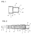
FIG. 2 shows a general construction diagram of an optical connector which
employs the clamp ring of this embodiment. As shown in FIG. 2; a ferrule 31, in
which an optical fibre 21 is inserted and fixed, has a flange 32. The stopper 34a is
fitted behind a rear end portion of the ferrule 31, in the back of the flange 32, with a
compression spring 33. Spring 33 is mounted on the outer periphery of the rear end
portion of the ferrule 31. A coated optical fibre 22 is inserted into the compression
spring 33 and the stopper 34a. A tensile strength member 24 of an optical fibre cable
23 is located at the rear end of the stopper 34b. The tensile strength member 24 is
secured between the clamp ring 10 and an outer peripheral surface of the rear end
portion of the stopper 34b by crimping.
As stated above; the inside diameter of the opening 14b, formed by the end
face 14a of the clamping portion 14, is slightly larger than the outside diameter of the
above-mentioned optical fibre cable. The outside diameter of the second annular
portion 12 is set to fit the diameter rating of the crimping tool used in the crimping
operation. The optical fibre cable 23 is clamped by the clamping portion 14 by
crimping the second annular portion 12 with the crimping tool. The tensile strength
member 24 is secured between the inside curved surface 11a of the first annular
portion 11 and the stopper 34, and between the inside surface 13a of the step portion
13 and the stopper 34, by crimping the first annular portion.
The clamp ring 10 of this embodiment provides the advantageous effects that it
can be produced extremely easily by press forming, for instance, and its crimping
operation can also be performed relatively easily.
Clamp rings of the invention and optical connectors employing the clamp rings
are not limited to the above-described embodiment in their basic construction. For
example, an optical connector may be a resin-molded product in which a flange, a
compression spring and a stopper are integrally formed.
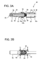
FIG. 3A-3B show an optical fibre terminating structure according to a second
embodiment of the present invention. A clamp ring 40 used in this embodiment
includes a main annular portion 41, which fits on the outer periphery of a rear end
portion of a ferrule. Ring 40 also has a clamping portion 42, which extends inward
from the rear end of the main annular portion 41 so that its innermost end clamps the
outer periphery of an optical fibre cable 23. The main annular portion 41 and the
clamping portion 42 are formed as a one-piece metallic part having an
approximately uniform thickness.
The inside diameter of an opening 42a formed by the clamping portion 42 is
made slightly larger than the outside diameter of the aforementioned optical fibre
cable 23. The outside diameter of the main annular portion 41 is set to fit the
diameter rating of a crimping tool used in the crimping operation. Further, the inside
diameter of the main annular portion 41 is made slightly larger than the diameter of
the outer periphery 53 of the rear end portion of the ferrule 51. Thus, the tensile
strength member 24 is secured between an inside curved surface 41a of the main
annular portion 41 and the outer periphery 53 of the ferrule 51. The parts are joined
by crimping both ends of the main annular portion 41 from around its outer
periphery.
The ferrule 51, in which an optical fibre 21 is inserted and fixed, has a flange
52. The outer periphery 53 of the rear end portion of the ferrule 51, on which the
aforementioned clamp ring 40 is fitted, is located in the back of the flange 52. In this
embodiment, three stepped ridges 54a-54c are integrally formed on the surface of the
outer periphery 53.
It is needless to say that the flange 52 may be produced either as a discrete
component (of stainless steel, for instance), or as an integral part of the ferrule.
The following discussion deals with a procedure for making a terminating
structure in which the optical fibre cable 23 is connected to the ferrule 51 using the
aforementioned clamp ring 40.
As shown in FIG. 3A, the clamp ring 40 is passed over the optical fibre cable
23. An outer covering, or jacket, of the optical fibre cable 23 is removed near its end
to expose the coated optical fibre 22, the tensile strength member 24 and the optical
fibre 21. The optical fibre 21 is inserted into an optical fibre insertion hole 25
of the ferrule 51 while the coated optical fibre 22 is inserted into a core insertion hole
26 of the ferrule 51. The optical fibre 21 and the coated optical fibre 22 are secured
in position with an adhesive readily filled in the aforementioned optical fibre
insertion hole 25 and the core insertion hole 26.
The tensile strength member 24 of the optical fibre cable 23 is located around
the outer periphery 53 of the rear end portion of the ferrule 51, thus being attached at
this point. With the tensile strength member 24 disposed between the clamp ring
40 and the outer peripheral surface of the rear end portion of the ferrule 51 at the
back of the flange 52; the clamp ring 40 is crimped and fixed by using the crimping
tool as shown in FIG. 3(b). Thus, the tensile strength member 24 can be secured in
position by crimping the ferrule side of the clamp ring 40. The jacket (formed of
PVC, for instance) of the optical fibre cable 23 can be secured by crimping the optical
fibre cable side of the clamp ring 40.
Subsequently, the far end of the ferrule 51 is polished together with the optical
fibre 21, to complete an optical fibre cable product already fitted with a ferrule.
As shown by the foregoing discussion, the present embodiment provides the
advantageous effects that it avoids the conventionally used adhesive, the optical
fibre cable 23 and the ferrule 51 can be joined together in an extremely simple and
easy way, and the optical fibre cable does not loose its flexibility.
Tensile tests carried out on ferrules, each joined to an optical fibre cable as
described, have proved that they could withstand tensile stresses of about 15 kgf.
On the other hand, a structure employing the conventional adhesive bond disjoined
under tensile stresses ranging from 3 to 4 kgf.
Although there are formed three stepped ridges 54 for clamping on the outer
periphery 53 of the rear end portion of the ferrule 51 in this embodiment, the number
of the stepped ridges 54 is not limited thereto in this invention. Moreover, the outer
periphery 53 of the rear end portion of the ferrule 51 may feature small pits and
protrusions on its surface (to form a so-called knurled surface) instead of forming the
aforementioned stepped ridges. The tensile strength member 24 is firmly retained by
such small pits and protrusions when the clamp ring is fitted.
Although a flange 52 on the ferrule 51 in this embodiment, its structure may
be varied by employing another type of clamp ring as shown in FIG. 4. In the
arrangement of figure 4, the outer periphery of the clamp ring 40 and that of a ferrule
51 have the same diameter. An outer peripheral part 73 of the rear end portion of the
ferrule 71 is made slightly smaller in diameter than the inside curved surface 41a of
the clamp ring 40. Thus, the optical fibre cable and the ferrule look like a one-piece
element when joined.
FIG. 5A-5B show an optical fibre terminating structure according to a third
embodiment of the invention.
As shown in FIG. 5, a clamp ring 60 used in this embodiment comprises: a
first annular portion 61; a second annular portion 62, having a smaller diameter than
the first annular portion 61; a step portion 63, connecting the first annular portion 61
and the second annular portion 62 to each other; and a clamping portion 64, which is
provided immediately adjacent to the rear end of the second annular portion 62 and
extends inward. All these potions are formed as a single piece, in a manner similar to
the first embodiment shown in FIG. 1. The inside diameter of an opening 64b,
formed by an end face 64a of the clamping portion 64, is made slightly larger
than the outside diameter of the earlier mentioned optical fibre cable. The outside
diameter of the second annular portion 62 is set to fit the diameter rating of a
crimping tool to be used in the crimping operation. Further, the diameter of the first
annular portion 61 is made slightly larger than the diameter of the outer
periphery 53 of the rear end portion of the ferrule 51. Thus, the tensile strength
member 24 is secured between an inside curved surface 61a of the first annular
portion 61 and the outer periphery 53 of the ferrule 51. The parts are joined by
crimping both ends of the first annular portion 61 from around its outer periphery.
The optical fibre terminating structure of this embodiment is made by
joining the optical fibre cable 23 to the ferrule 51 by using the clamp ring 60 in a
manner similar to the second embodiment.
The clamp ring 60 is passed over the optical fibre cable 23. The optical fibre
21 is inserted into the optical fibre insertion hole 25 of the ferrule 51. The coated
optical fibre 22 is inserted into the core insertion hole 26 of the ferrule 51. The
optical fibre and the coated optical fibre 22 are secured in position with an adhesive,
as shown in FIG. 5A.
The tensile strength member 24, located around the outer periphery 53 of the
rear end portion of the ferrule 51, is disposed between the inside curved surface of the
clamp ring 60 and the outer peripheral surface of the rear end portion of the ferrule 51
at the back of the flange 52. The clamp ring 60 is crimped and fixed by using the
crimping tool as shown in FIG. 5B. Thus, the tensile strength member 24 can be
secured between the outer periphery 53 of the rear end portion of the ferrule 51 and
the inside curved surface 61a of the first annular portion 61. This is achieved by
crimping the first annular portion 61 of the clamp ring 60 from around its outer
peripheral surface. The tensile strength member 24 can also be secured between the
outer periphery 53 of the rear end portion of the ferrule and an inside curved surface
63a of the step portion 63, to provide increased fixing strength. This is achieved by
crimping the first annular portion 61 of the clamp ring 60 from around its outer
peripheral surface. Furthermore, the jacket (formed of PVC, for instance) of the
optical fibre cable 23 can be secured by clamping it by the end face 64a at the
clamping portion 64.
As shown by the foregoing discussion, the present embodiment provides
advantages, as does the earlier-described embodiment, in that it becomes unnecessary
to use the conventionally used adhesive. The optical fibre cable 23 and the ferrule 51
can be joined together in an extremely simple and easy way. Further, the optical
fibre cable does not loose its flexibility. This embodiment makes it possible to join
the optical fibre to the ferrule even more firmly.
The clamp rings of the present invention are easy to produce and their
crimping operation can be performed relatively easily. They are formed to have
approximately a uniform thickness throughout their whole structure. The outer
periphery of the optical fibre cable is clamped by the end face of the clamping portion
which extends inward from the rear end of the second annular portion as
described above.
The optical fibre terminating structures of the present invention provide
advantageous effects in that they facilitate the fixing operation due to their
construction. That is, the clamp rings have an approximately uniform thickness
throughout. The tensile strength member is secured by crimping the clamp ring fitted
over the outer periphery of the rear end portion of each ferrule. Further, the number
of processes and labour hours required for the fixing operation can be reduced,
since the individual components can be fixed together without using an adhesive
unlike the conventional structure.