EP0664467A1 - Force transfer system for an optical fiber connector - Google Patents
Force transfer system for an optical fiber connector Download PDFInfo
- Publication number
- EP0664467A1 EP0664467A1 EP95300149A EP95300149A EP0664467A1 EP 0664467 A1 EP0664467 A1 EP 0664467A1 EP 95300149 A EP95300149 A EP 95300149A EP 95300149 A EP95300149 A EP 95300149A EP 0664467 A1 EP0664467 A1 EP 0664467A1
- Authority
- EP
- European Patent Office
- Prior art keywords
- wedge
- connector
- optical fiber
- cantilevers
- cantilever
- Prior art date
- Legal status (The legal status is an assumption and is not a legal conclusion. Google has not performed a legal analysis and makes no representation as to the accuracy of the status listed.)
- Withdrawn
Links
Images


Classifications
-
- G—PHYSICS
- G02—OPTICS
- G02B—OPTICAL ELEMENTS, SYSTEMS OR APPARATUS
- G02B6/00—Light guides; Structural details of arrangements comprising light guides and other optical elements, e.g. couplings
- G02B6/24—Coupling light guides
- G02B6/36—Mechanical coupling means
- G02B6/38—Mechanical coupling means having fibre to fibre mating means
- G02B6/3807—Dismountable connectors, i.e. comprising plugs
- G02B6/3873—Connectors using guide surfaces for aligning ferrule ends, e.g. tubes, sleeves, V-grooves, rods, pins, balls
- G02B6/3874—Connectors using guide surfaces for aligning ferrule ends, e.g. tubes, sleeves, V-grooves, rods, pins, balls using tubes, sleeves to align ferrules
- G02B6/3878—Connectors using guide surfaces for aligning ferrule ends, e.g. tubes, sleeves, V-grooves, rods, pins, balls using tubes, sleeves to align ferrules comprising a plurality of ferrules, branching and break-out means
-
- G—PHYSICS
- G02—OPTICS
- G02B—OPTICAL ELEMENTS, SYSTEMS OR APPARATUS
- G02B6/00—Light guides; Structural details of arrangements comprising light guides and other optical elements, e.g. couplings
- G02B6/24—Coupling light guides
- G02B6/36—Mechanical coupling means
- G02B6/38—Mechanical coupling means having fibre to fibre mating means
- G02B6/3807—Dismountable connectors, i.e. comprising plugs
- G02B6/3887—Anchoring optical cables to connector housings, e.g. strain relief features
- G02B6/3888—Protection from over-extension or over-compression
Definitions
- This invention relates generally to connectors for terminating optical cables, and more particularly to a connector having an improved design for transferring forces from the cable to the connector.
- optical fibers in communication systems are growing at an unprecedented rate.
- Low loss optical fibers which are produced by any of several techniques may be stranded into cables, or enclosed individually in a jacket and used in the transmission of large amounts of information which is typically binary (i.e., on/off pulses).
- An optical fiber comprises a thin glass fiber which has been processed to confine light along its longitudinal axis, and then enclosed within one or more layers of a protective coating material that cushions the glass fiber against severe bending and protects it from contaminants such as water vapor to preserve its inherently high tensile strength. In some applications, no additional jacketing is applied to the individual fibers; however, in other applications is it necessary to add a buffer material around each coated fiber.
- a layer of nylon or polyvinylchloride, for example, is extruded around the individual optical fibers to form what is known as a "buffered optical fiber.”
- a layer of nylon or polyvinylchloride for example, is extruded around the individual optical fibers to form what is known as a "buffered optical fiber.”
- one or more of these buffered fibers is combined with strength members of various types and covered with a polymer jacket or sheath.
- optical fiber connectors particularly duplex connectors which are used for making connections to a pair of optical fibers
- These tensile forces are also coupled to the optical fiber(s) which reside in the cable and, without proper restraint, will pull the fibers from the connector back into the cable.
- Such shortening of the fibers inside the connector case can cause high-stress bending where the fiber is joined to a plug assembly thereby causing a decrease in long-term reliability.
- a known technique for immobilizing buffered fibers within a duplex optical fiber connector utilizes a cylindrical rubber grommet which is secured within the connector housing. Epoxy is applied to prevent the grommet itself from moving due to exposure to high/low temperature extremes.
- the grommet includes three openings that are arrayed in a triangular pattern and extend between opposite ends of the grommet along a direction that is parallel to its central axis. Two of the openings are grooved to facilitate gripping the buffered fiber. The remaining opening is smooth and receives a metal pin which, when inserted, causes the grooved openings to compress around the buffered fibers to hold them securely. And while this technique is useful for immobilizing buffered fibers within an optical fiber connector, it is somewhat expensive, it requires careful manual assembly, and adhesive materials must be handled and cured.
- a force transfer system comprising a wedge positioned within a bushing for gripping one or more optical fibers within a connector.
- the bushing includes a passageway which is shaped to receive the wedge.
- the wedge includes a body portion having a pair of flexible cantilevers that extend from one end of the body portion and are parallel to each other.
- Each cantilever includes an inner surface that faces the inner surface of the other cantilever. At least one of the inner surfaces is adapted to grip the optical fiber.
- each cantilever includes an equal number of grooves that are parallel to each other and perpendicular to the longitudinal axis of the wedge.
- the cantilevers are symmetrically positioned on opposite sides of a plane which contains the longitudinal axis of the wedge.
- Each cantilever includes a pair of semicircularly shaped channels at its free end for receiving a pair of buffered optical fibers.
- the bushing is made from a deformable material which is crimped at one end to apply a force to the cantilevers, thereby causing the cantilevers to move toward each other and grip the buffered optical fibers positioned therebetween.
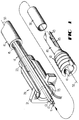
- FIG. 1 is an exploded perspective view of a force transfer system for use in an optical fiber connector.
- Cable 10 includes two buffered optical fibers 13, each of which comprises a glass fiber 11 enclosed within a coating system 12 and a buffer layer of a plastic material such as polyvinyl chloride (PVC) or nylon.
- PVC polyvinyl chloride
- the buffered optical fibers 13 are enclosed in a common plastic jacket 15 and non-metallic strength member system comprising aramid yarn 14 disposed between the optical fibers and the jacket.
- Bushing 20 is a cylindrically shaped body having a flange 21 at one end thereof which is used for holding the bushing within an optical fiber connector (see FIG. 3).
- the bushing is, illustratively, die cast from a zinc alloy such as Zamac 5 so that it is sufficiently rigid but still deformable in a crimping operation.
- Passageway 25 of the bushing 20 is tapered at a 3-degree included angle to cooperate with a wedge 40 of the force transfer system in securing strength member yarn 14 therebetween.
- a portion of the cable extends into the bushing beyond crimping area 23 with its jacket removed in order to expose strength member 14, and to allow the buffered optical fibers 13 to extend through passageway 25 toward the flanged end of the bushing 20.
- the wedge 40 has an outer surface which is adapted to mate with the inner surface of passageway 25 of the bushing (i.e., its outer dimensions are substantially the same as the inner dimensions of the passageway). Additionally, the wedge 40 includes a number of concentric ribs 42-42 around its outer surface which help secure the yarn. Strength member yarn 14 is thus captured between the outer surface of wedge 40 and the inner surface of bushing 20, and the bushing is fixed with respect to an associated connector (see FIG. 3) inasmuch as its flange 21 is secured to the connector housing. As a result, portions of the strength member system 14 are held between these surfaces, and any force which is imparted to the cable 10 is transferred by the strength member system to the connector.
- the force transfer system of the present invention also functions to secure the buffered optical fibers 13-13 so that forces imparted to the cable are transferred to the wedge 40.
- the length of fiber within the connector is critical inasmuch as too much fiber leads to severe bending of the fiber (bend radius is too small), and too little fiber leads to the creation of high stress points at the junction where the optical fiber is joined to a ferrule/barrel assembly.
- Wedge 40 includes cantilevers 43-43 (sometimes also referred to as "jaws") that extend from the cable-entrance end of the wedge and are used for grasping buffered optical fibers 13-13 when they are closed.
- Alignment notches 41-41 located at the other end of the wedge, are used for maintaining the wedge in a predetermine orientation with respect to the bushing.
- crimping forces, applied to jaws 43-43 be approximately orthogonal to a plane that passes between the opening in the jaws, along longitudinal axis 50, and through alignment notches 41-41. This is accomplished by using a tool (not shown) which includes pins that engage notches 41-41 during the insertion of wedge 40 into bushing 20.
- each cantilever 43 includes a number of spaced-apart grooves 45 which are parallel to each other, but perpendicular to the longitudinal axis 50.
- a thin-walled tube (sleeve 30) is placed around jaws 43 after the buffered fibers have been inserted between the jaws.
- the sleeve is made from a heatshrinkable plastic material, and functions to preclude the strength members 14 from interfering with the buffered optical fibers during a subsequent crimping operation. Assembling the wedge 40 and bushing 20 to the cable 10 will be described more clearly when reference is made to FIG. 2A-2C. And although crimping is a preferred technique for bringing the jaws into engagement with the optical fibers, it is clearly possible to shape the interior of the bushing with a camming surface such that the jaws close as the wedge advances into the bushing.
- Cable 10, including outer jacket 15, is inserted through passageway 25 of bushing 20. Thereafter, an end portion of the outer jacket is removed to expose a pair of buffered optical fibers surrounded by non-metallic, filamentary strength members 14.
- the strength members are pulled back so the buffered optical fibers 13-13 can be inserted through sleeve 30 and jaws 43-43 of the wedge 40 along their common longitudinal axis 50.
- Sleeve 30, which has been previously installed around jaws 43-43, is now heated so that it will shrink and thereby seal the jaws to preclude any unwanted material (e.g., strength members 14) from entering between the jaws.
- FIG. 2A shows the assembly described thus far. At this point, the teeth 45 of jaws 43-43 barely touch the buffered optical fibers 13.
- the teeth are mirror images of each other, so that when they are pressed together there is equal pressure on opposite sides of each optical fiber. Accordingly, no forces can be applied that would tend to create microbends in the optical fiber.
- Strength members 14 circumferentially surround wedge 40, and when the wedge is pressed into bushing 20, its ridges 42 function to capture them. When the assembly of bushing, wedge and cable are carried out, the buffered fibers feed through the wedge and its jaws, the strength members are trapped between the wedge and the tapered inner surface of the bushing, and the outer cable jacket is between the jaws and the necked-down end of the bushing. At this point, the end 23 of the bushing 20 is crimped.
- FIG. 2B shows the wedge fully positioned within the bushing after a crimping force has been applied to crimping surface 23 of the bushing.
- the teeth 45 each have a cross section of a buttress thread which precludes the buffered fiber, captured therebetween, from being pulled back into the cable 10 during subsequent handling.
- the crimping operation causes the teeth 45 to deform the buffer material surrounding the optical fiber without harming the optical fiber itself. This is illustrated more clearly in the cross sectional view of FIG. 2C which shows (via a dotted line) that although the teeth 45 engage the buffered fiber 13, they do not deform the glass fiber itself. Note that the coating is stripped from optical fiber 11 before it is subsequently installed in a ferrule.
- wedge 40 is molded from PEI (Polyetherimide) material which is 30% glass filled and annealed to provide optimum performance when gripping buffered fibers -- particularly optical fibers using a nylon buffer material.
- PEI Polyetherimide
- FIG. 2C also shows flange 21 which is used in a duplex connector, as described below, for transferring forces from the cable to the connector.
- FIG. 3 and 4 respectively disclose perspective and top views of a duplex connector in accordance with the invention whose general structure and operation are more completely described in U.S. Patent 4,787,706 which is hereby incorporated by reference.
- the duplex connector disclosed in the above-referenced patent does not include any apparatus for transferring forces from either of the buffered fibers contained therein to the connector housing other than a connection between the fiber 13 and the barrel 320 -- a potentially a high-stress point corresponding to connection 340 shown in FIG. 4.
- the present invention avoids such stress by precluding movement of the buffered fiber within the duplex connector in a novel manner.
- Each buffered fiber 13 is mechanically connected (see junction 340) to a plug assembly comprising ferrule 310 and barrel 320.
- the barrel includes a cavity which receives and holds the ferrule.
- An optical fiber extends through the central axis of the plug assembly and guides lightwaves used for communicating information. So that the lightwaves can be efficiently connected to another optical device (not shown), the plug assembly is pressed against the optical device or the like by spring 330 which provides a controlled force in the appropriate direction.
- FIG. 9 discloses a known force transfer system used in prior art duplex connectors.
- the transfer of force from the buffered fibers to the duplex connector is via grommet 90, wedge 60 and bushing 20.
- buffered fibers 13-13 are threaded through openings 91-91 in grommet 90, an adhesive material (e.g., epoxy) is applied to the grommet, and the grommet is pressed into longitudinally extending passageway 65 of wedge 60. Openings 91-91 are grooved to facilitate gripping the buffered fibers.
- an adhesive material e.g., epoxy
- a metal pin 95 is inserted into a longitudinally extending groove 92 along the outer surface of the grommet which causes the openings 91-91 to compress around the buffered fibers to hold them securely.
- the pin 95 includes features 97, 98 which facilitate its insertion into groove 92 but hinder its removal. Since the pin is slightly larger than the groove, and since the grommet is made from a deformable material, such as rubber, insertion of the pin into the groove compresses the size of openings 91-91 to capture the buffered fibers therein.
- FIG. 3 and 4 an improved force transfer system is shown within duplex connector 300.
- Bushing 20 surrounds wedge 40 and captures strength members 14 therebetween.
- Flange 21 of the bushing cooperates with mating recesses molded into the connector to fix their relative positions. Any forces transferred to bushing 20 from the cable 10 are subsequently transferred, via flange 21, to connector 300.
- cable 10 is pulled, for example, not only do its strength members 14 transfer a portion of the pulling force to the bushing, but so do fibers 13-13 which are clamped between the jaws of bushing (see FIG. 2B).
- Use of this novel force transfer system not only reduces the number of components needed to assemble a duplex connector, but it also eliminates the labor-intensive step of threading optical fibers through a grommet.
- strain-relief boot 350 not only transfers a small portion of the pulling force from the cable 10 but, more importantly, it enables the cable to withstand repeated bends after interconnection with an optical device (possibly another cable) without undue stress being imparted to the optical fiber.
- a suitable material for the boot is Santoprene(r) elastomer -- a somewhat rigid thermoplastic which is commercially available from Monsanto Chemical Company.
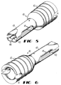
- FIG. 5 is a perspective view of an embodiment of the wedge of the present invention as viewed from the end having cantilevers with grooves for gripping a pair of optical fibers. Note the semicircularly shaped channels 44-44 at one end of wedge 40 that hold the buffered fibers in a fixed relative position with respect to each other. These channels prevent the fibers from being moved to a different, and possibly disadvantageous, position during crimping.
- FIG. 6 shows a perspective view of the embodiment of the wedge shown in FIG. 5 viewed from the end opposite the cantilevers.
- the outside surface of wedge 40 is tapered at about a 3-degree angle to enhance its "wedging" function.
- the circumference of the wedge is slightly greater in the region of the alignment notches 41 than in the region which is closer to the cantilevers 43-43.
- FIG. 7 is a perspective view of a second embodiment of a wedge 70 in accordance with the present invention.
- This particular wedge design includes alignment notches 71, circumferential ribs 72 and grooves 75 which operate in the same manner as their functional counterparts shown in FIG. 5 and 6.
- this design is slightly different in that the cantilevers 73 do not include semicircularly shaped channels for holding the buffered fibers in a fixed relative position with respect to each other. And while such channels are advantageous, the design of FIG. 7 provides most of the benefits of the invention.
- FIG. 8 is a side elevation view, in cross section, of a simplex connector 800 in accordance with the present invention.
- the device shown is an ST(r) connector which is used to terminate a cable 10 having a single optical fiber -- "ST" being a registered trademark of AT&T.
- This particular connector includes a plug assembly comprising ferrule 310 and barrel 80.
- the connector further comprises spring 330, cap 83, and cap extender 87.
- Ferrule 310 is a ceramic or glass cylinder which is adapted to receive a glass fiber 11 whose protective coating has been removed into an axially disposed opening that extends between opposite ends thereof. The ferrule then fits into a cavity at one end of barrel 80 which is shaped to receive it.
- the barrel may be a machined or molded part, and may be made from metal or plastic material, and the plug assembly is urged toward the plug end of cap 83 by compression spring 330 so that a when a pair of ferrules are butted together in a coupling sleeve, one or both of the ferrules is moved along its longitudinal axis during the connection process.
- barrel 80 includes a bore 89 through its longitudinal axis which holds the buffered fiber 13 therein.
- the connector 800 may be connected to a coupling apparatus (not shown) by so-called bayonet motion in which the connector is inserted with linear motion into the coupling apparatus and turned to cause projecting pins of the coupling apparatus to be moved along camming slots 84-84 of the cap, and to cause a key 82 of the connector to become disposed in a slot of the coupling apparatus.
- Cap extender 87 includes an external threaded portion which is turned into the threaded entrance of the cap and secured thereto. The extender 87 is bonded to the cap 83 after it has been turned fully thereinto.
- Compression spring 330 is disposed about a portion of the barrel 80 between, and in engagement with, lip 85 and an enlarged end portion of the barrel. As a result of this arrangement, the spring 330 biases the barrel 80 outwardly from the cap 83 while a retaining clip 86 holds the plug assembly within the cap.
- Barrel 80 includes two cantilevers 43 that are disposed at the cable-entrance end thereof. Each cantilever includes a plurality of grooves 45 that are parallel to each other and are used to firmly hold buffered fiber 13. By using grooved cantilevers it is possible to eliminate the need for adhesives, such as epoxy, within the bore 89 of barrel 80 -- advantageously avoiding the labor and mess associated with handling such materials.
- the fiber-entrance end of barrel 80 At the fiber-entrance end of the barrel 80, externally disposed circumferential ribs 42 are provided for the purpose of cooperating with a bushing 20 to capture the yarn-like strength members 14 that reside within cable 10.
- the bushing 20 is crimped in the region of cantilevers 43 thereby causing the grooves (teeth) of the cantilevers to close onto the buffered fiber.
- the fiber-entrance end of barrel 80 has the functionality of the previously discussed wedge incorporated therein to form a force transfer system that not only transfers force from the strength members to the connector, but also from the buffered fiber to the connector.
Abstract
An optical fiber connector 300 includes a wedge 40 for gripping one or more buffered optical fibers 13-13. The wedge comprises a body portion having an opening that extends through it from one end to the other through a longitudinal axis of the wedge for receiving the pair of optical fibers contained within a cable 10. The wedge further includes a pair of flexible cantilevers 43-43 that extend from one end of the body portion along a direction that is parallel to the longitudinal axis. Each cantilever includes an inner surface that faces the inner surface of the other cantilever, and each inner surface includes an like number of grooves 45 that are parallel to each other and perpendicular to the longitudinal axis of the wedge. The grooves grip the pair of buffered optical fibers when compressed by crimping a surrounding bushing 30, and thereby restrain the optical fibers from being pulled back into the cable during handling. The cantilevers are symmetrically positioned on opposite sides of a plane which contains the longitudinal axis of the wedge.
Description
- This invention relates generally to connectors for terminating optical cables, and more particularly to a connector having an improved design for transferring forces from the cable to the connector.
- The use of optical fibers in communication systems is growing at an unprecedented rate. Low loss optical fibers which are produced by any of several techniques may be stranded into cables, or enclosed individually in a jacket and used in the transmission of large amounts of information which is typically binary (i.e., on/off pulses). An optical fiber comprises a thin glass fiber which has been processed to confine light along its longitudinal axis, and then enclosed within one or more layers of a protective coating material that cushions the glass fiber against severe bending and protects it from contaminants such as water vapor to preserve its inherently high tensile strength. In some applications, no additional jacketing is applied to the individual fibers; however, in other applications is it necessary to add a buffer material around each coated fiber. In these situations, a layer of nylon or polyvinylchloride, for example, is extruded around the individual optical fibers to form what is known as a "buffered optical fiber." In most interconnection cable applications, one or more of these buffered fibers is combined with strength members of various types and covered with a polymer jacket or sheath.
- In optical fiber connectors, particularly duplex connectors which are used for making connections to a pair of optical fibers, it is necessary to provide a force transfer system at the cable-entrance end of the connector to hold strength members of the cable in such a manner that tensile forces on the cable are transferred to the housing of the connector. These tensile forces are also coupled to the optical fiber(s) which reside in the cable and, without proper restraint, will pull the fibers from the connector back into the cable. Such shortening of the fibers inside the connector case can cause high-stress bending where the fiber is joined to a plug assembly thereby causing a decrease in long-term reliability.
- A known technique for immobilizing buffered fibers within a duplex optical fiber connector utilizes a cylindrical rubber grommet which is secured within the connector housing. Epoxy is applied to prevent the grommet itself from moving due to exposure to high/low temperature extremes. The grommet includes three openings that are arrayed in a triangular pattern and extend between opposite ends of the grommet along a direction that is parallel to its central axis. Two of the openings are grooved to facilitate gripping the buffered fiber. The remaining opening is smooth and receives a metal pin which, when inserted, causes the grooved openings to compress around the buffered fibers to hold them securely. And while this technique is useful for immobilizing buffered fibers within an optical fiber connector, it is somewhat expensive, it requires careful manual assembly, and adhesive materials must be handled and cured.
- What is needed, and what is not supplied by the prior art, is a force transfer system for use within a connector that grips one or more optical fibers in a manner which is cost effective, easy to assemble, and preferably avoids the use of adhesives.
- The foregoing problems are solved by a force transfer system comprising a wedge positioned within a bushing for gripping one or more optical fibers within a connector. The bushing includes a passageway which is shaped to receive the wedge. The wedge includes a body portion having a pair of flexible cantilevers that extend from one end of the body portion and are parallel to each other. Each cantilever includes an inner surface that faces the inner surface of the other cantilever. At least one of the inner surfaces is adapted to grip the optical fiber.
- In a preferred embodiment of the invention, the inner surface of each cantilever includes an equal number of grooves that are parallel to each other and perpendicular to the longitudinal axis of the wedge. The cantilevers are symmetrically positioned on opposite sides of a plane which contains the longitudinal axis of the wedge. Each cantilever includes a pair of semicircularly shaped channels at its free end for receiving a pair of buffered optical fibers. The bushing is made from a deformable material which is crimped at one end to apply a force to the cantilevers, thereby causing the cantilevers to move toward each other and grip the buffered optical fibers positioned therebetween.
- The invention and its mode of operation will be more clearly understood from the following detailed description when read with the appended drawing in which:
- FIG. 1 is an exploded perspective view of an optical fiber connector in accordance with the present invention;
- FIG. 2A is a side elevation view, in cross section, of the optical fiber connector showing the position of cooperating components before closure of a wedge onto an optical fiber;
- FIG. 2B is a side elevation view, in cross section, of the optical fiber connector showing the position of cooperating components after closure of the wedge onto the optical fiber;
- FIG. 2C is an end view of FIG. 2B showing a pair of buffered optical fibers being held within the jaws of the wedge;
- FIG. 3 is a perspective view of a duplex connector in accordance with the invention with portions thereof broken away;
- FIG. 4 is a plan view, partially in section, of the duplex connector of FIG. 3;
- FIG. 5 is a perspective view of an embodiment of the wedge of the present invention as viewed from the end having cantilevers with grooves for gripping a pair of optical fibers;
- FIG. 6 is a perspective view of the embodiment of the wedge shown in FIG. 5 viewed from the end opposite the cantilevers;
- FIG. 7 is a perspective view of a second embodiment of the wedge of the present invention as viewed from the end having cantilevers with grooves for gripping an optical fiber(s);
- FIG. 8 is a side elevation view, in cross section, of a simplex connector in accordance with the present invention; and
- FIG. 9 is an exploded perspective view of a prior art duplex connector.
- FIG. 1 is an exploded perspective view of a force transfer system for use in an optical fiber connector. In particular, the interaction between significant parts of the force transfer system and
optical cable 10 is illustrated.Cable 10 includes two bufferedoptical fibers 13, each of which comprises aglass fiber 11 enclosed within a coating system 12 and a buffer layer of a plastic material such as polyvinyl chloride (PVC) or nylon. The bufferedoptical fibers 13 are enclosed in a commonplastic jacket 15 and non-metallic strength member system comprisingaramid yarn 14 disposed between the optical fibers and the jacket. -
Bushing 20 is a cylindrically shaped body having aflange 21 at one end thereof which is used for holding the bushing within an optical fiber connector (see FIG. 3). The bushing is, illustratively, die cast from a zinc alloy such as Zamac 5 so that it is sufficiently rigid but still deformable in a crimping operation. Passageway 25 of thebushing 20 is tapered at a 3-degree included angle to cooperate with awedge 40 of the force transfer system in securingstrength member yarn 14 therebetween. A portion of the cable extends into the bushing beyondcrimping area 23 with its jacket removed in order to exposestrength member 14, and to allow the bufferedoptical fibers 13 to extend throughpassageway 25 toward the flanged end of thebushing 20. Thewedge 40 has an outer surface which is adapted to mate with the inner surface ofpassageway 25 of the bushing (i.e., its outer dimensions are substantially the same as the inner dimensions of the passageway). Additionally, thewedge 40 includes a number of concentric ribs 42-42 around its outer surface which help secure the yarn.Strength member yarn 14 is thus captured between the outer surface ofwedge 40 and the inner surface ofbushing 20, and the bushing is fixed with respect to an associated connector (see FIG. 3) inasmuch as itsflange 21 is secured to the connector housing. As a result, portions of thestrength member system 14 are held between these surfaces, and any force which is imparted to thecable 10 is transferred by the strength member system to the connector. However, the force transfer system of the present invention also functions to secure the buffered optical fibers 13-13 so that forces imparted to the cable are transferred to thewedge 40. The length of fiber within the connector is critical inasmuch as too much fiber leads to severe bending of the fiber (bend radius is too small), and too little fiber leads to the creation of high stress points at the junction where the optical fiber is joined to a ferrule/barrel assembly. - Wedge 40 includes cantilevers 43-43 (sometimes also referred to as "jaws") that extend from the cable-entrance end of the wedge and are used for grasping buffered optical fibers 13-13 when they are closed. Alignment notches 41-41, located at the other end of the wedge, are used for maintaining the wedge in a predetermine orientation with respect to the bushing. In particular, it is important that crimping forces, applied to jaws 43-43, be approximately orthogonal to a plane that passes between the opening in the jaws, along
longitudinal axis 50, and through alignment notches 41-41. This is accomplished by using a tool (not shown) which includes pins that engage notches 41-41 during the insertion ofwedge 40 into bushing 20. The tool is oriented so that the aforementioned plane is parallel to the top surface offlange 21 as seen in FIG. 1. Accordingly, forces applied to crimpingregion 23 in a direction which is orthogonal to the top surface offlange 21, will be properly aligned to closejaws 43 onto the buffered optical fibers 13-13. The inner surface of eachcantilever 43 includes a number of spaced-apartgrooves 45 which are parallel to each other, but perpendicular to thelongitudinal axis 50. A thin-walled tube (sleeve 30) is placed aroundjaws 43 after the buffered fibers have been inserted between the jaws. The sleeve is made from a heatshrinkable plastic material, and functions to preclude thestrength members 14 from interfering with the buffered optical fibers during a subsequent crimping operation. Assembling thewedge 40 andbushing 20 to thecable 10 will be described more clearly when reference is made to FIG. 2A-2C. And although crimping is a preferred technique for bringing the jaws into engagement with the optical fibers, it is clearly possible to shape the interior of the bushing with a camming surface such that the jaws close as the wedge advances into the bushing. -
Cable 10, includingouter jacket 15, is inserted throughpassageway 25 ofbushing 20. Thereafter, an end portion of the outer jacket is removed to expose a pair of buffered optical fibers surrounded by non-metallic,filamentary strength members 14. The strength members are pulled back so the buffered optical fibers 13-13 can be inserted throughsleeve 30 and jaws 43-43 of thewedge 40 along their commonlongitudinal axis 50.Sleeve 30, which has been previously installed around jaws 43-43, is now heated so that it will shrink and thereby seal the jaws to preclude any unwanted material (e.g., strength members 14) from entering between the jaws. FIG. 2A shows the assembly described thus far. At this point, theteeth 45 of jaws 43-43 barely touch the bufferedoptical fibers 13. Note that the teeth are mirror images of each other, so that when they are pressed together there is equal pressure on opposite sides of each optical fiber. Accordingly, no forces can be applied that would tend to create microbends in the optical fiber.Strength members 14circumferentially surround wedge 40, and when the wedge is pressed intobushing 20, itsridges 42 function to capture them. When the assembly of bushing, wedge and cable are carried out, the buffered fibers feed through the wedge and its jaws, the strength members are trapped between the wedge and the tapered inner surface of the bushing, and the outer cable jacket is between the jaws and the necked-down end of the bushing. At this point, theend 23 of thebushing 20 is crimped. This action transfers a deforming force through thecable jacket 15 to the cantilevers 43-43 of the wedge. The grooved cantilevers are pressed into the plastic of the buffered fiber to provide a secure engagement. The crimp size is selected to assure sufficient buffer penetration by the grooves without damage to the optical fiber. FIG. 2B shows the wedge fully positioned within the bushing after a crimping force has been applied to crimpingsurface 23 of the bushing. - The
teeth 45 each have a cross section of a buttress thread which precludes the buffered fiber, captured therebetween, from being pulled back into thecable 10 during subsequent handling. The crimping operation causes theteeth 45 to deform the buffer material surrounding the optical fiber without harming the optical fiber itself. This is illustrated more clearly in the cross sectional view of FIG. 2C which shows (via a dotted line) that although theteeth 45 engage the bufferedfiber 13, they do not deform the glass fiber itself. Note that the coating is stripped fromoptical fiber 11 before it is subsequently installed in a ferrule. In a preferred embodiment of the invention,wedge 40 is molded from PEI (Polyetherimide) material which is 30% glass filled and annealed to provide optimum performance when gripping buffered fibers -- particularly optical fibers using a nylon buffer material. However, other materials such as zinc may also be used for the wedge. FIG. 2C also showsflange 21 which is used in a duplex connector, as described below, for transferring forces from the cable to the connector. - FIG. 3 and 4 respectively disclose perspective and top views of a duplex connector in accordance with the invention whose general structure and operation are more completely described in U.S. Patent 4,787,706 which is hereby incorporated by reference. However, the duplex connector disclosed in the above-referenced patent does not include any apparatus for transferring forces from either of the buffered fibers contained therein to the connector housing other than a connection between the
fiber 13 and thebarrel 320 -- a potentially a high-stress point corresponding toconnection 340 shown in FIG. 4. The present invention avoids such stress by precluding movement of the buffered fiber within the duplex connector in a novel manner. Consider the relevant components withinduplex connector 300 to more fully understand its operation. Each bufferedfiber 13 is mechanically connected (see junction 340) to a plugassembly comprising ferrule 310 andbarrel 320. The barrel includes a cavity which receives and holds the ferrule. An optical fiber extends through the central axis of the plug assembly and guides lightwaves used for communicating information. So that the lightwaves can be efficiently connected to another optical device (not shown), the plug assembly is pressed against the optical device or the like byspring 330 which provides a controlled force in the appropriate direction. - Reference is briefly made to FIG. 9 which discloses a known force transfer system used in prior art duplex connectors. In particular, the transfer of force from the buffered fibers to the duplex connector is via
grommet 90,wedge 60 andbushing 20. In this design, buffered fibers 13-13 are threaded through openings 91-91 ingrommet 90, an adhesive material (e.g., epoxy) is applied to the grommet, and the grommet is pressed into longitudinally extendingpassageway 65 ofwedge 60. Openings 91-91 are grooved to facilitate gripping the buffered fibers. Thereafter, ametal pin 95 is inserted into alongitudinally extending groove 92 along the outer surface of the grommet which causes the openings 91-91 to compress around the buffered fibers to hold them securely. Thepin 95 includesfeatures groove 92 but hinder its removal. Since the pin is slightly larger than the groove, and since the grommet is made from a deformable material, such as rubber, insertion of the pin into the groove compresses the size of openings 91-91 to capture the buffered fibers therein. - Returning now to FIG. 3 and 4, an improved force transfer system is shown within
duplex connector 300.Bushing 20 surroundswedge 40 and capturesstrength members 14 therebetween.Flange 21 of the bushing cooperates with mating recesses molded into the connector to fix their relative positions. Any forces transferred to bushing 20 from thecable 10 are subsequently transferred, viaflange 21, toconnector 300. Whencable 10 is pulled, for example, not only do itsstrength members 14 transfer a portion of the pulling force to the bushing, but so do fibers 13-13 which are clamped between the jaws of bushing (see FIG. 2B). Use of this novel force transfer system not only reduces the number of components needed to assemble a duplex connector, but it also eliminates the labor-intensive step of threading optical fibers through a grommet. And finally, strain-relief boot 350 not only transfers a small portion of the pulling force from thecable 10 but, more importantly, it enables the cable to withstand repeated bends after interconnection with an optical device (possibly another cable) without undue stress being imparted to the optical fiber. A suitable material for the boot is Santoprene(r) elastomer -- a somewhat rigid thermoplastic which is commercially available from Monsanto Chemical Company. - FIG. 5 is a perspective view of an embodiment of the wedge of the present invention as viewed from the end having cantilevers with grooves for gripping a pair of optical fibers. Note the semicircularly shaped channels 44-44 at one end of
wedge 40 that hold the buffered fibers in a fixed relative position with respect to each other. These channels prevent the fibers from being moved to a different, and possibly disadvantageous, position during crimping. FIG. 6 shows a perspective view of the embodiment of the wedge shown in FIG. 5 viewed from the end opposite the cantilevers. Although not fully apparent in these figures, the outside surface ofwedge 40 is tapered at about a 3-degree angle to enhance its "wedging" function. The circumference of the wedge is slightly greater in the region of thealignment notches 41 than in the region which is closer to the cantilevers 43-43. - FIG. 7 is a perspective view of a second embodiment of a
wedge 70 in accordance with the present invention. This particular wedge design includesalignment notches 71,circumferential ribs 72 andgrooves 75 which operate in the same manner as their functional counterparts shown in FIG. 5 and 6. However, this design is slightly different in that thecantilevers 73 do not include semicircularly shaped channels for holding the buffered fibers in a fixed relative position with respect to each other. And while such channels are advantageous, the design of FIG. 7 provides most of the benefits of the invention. - FIG. 8 is a side elevation view, in cross section, of a simplex connector 800 in accordance with the present invention. The device shown is an ST(r) connector which is used to terminate a
cable 10 having a single optical fiber -- "ST" being a registered trademark of AT&T. This particular connector includes a plugassembly comprising ferrule 310 andbarrel 80. The connector further comprisesspring 330,cap 83, andcap extender 87.Ferrule 310 is a ceramic or glass cylinder which is adapted to receive aglass fiber 11 whose protective coating has been removed into an axially disposed opening that extends between opposite ends thereof. The ferrule then fits into a cavity at one end ofbarrel 80 which is shaped to receive it. The barrel may be a machined or molded part, and may be made from metal or plastic material, and the plug assembly is urged toward the plug end ofcap 83 bycompression spring 330 so that a when a pair of ferrules are butted together in a coupling sleeve, one or both of the ferrules is moved along its longitudinal axis during the connection process. As shown,barrel 80 includes abore 89 through its longitudinal axis which holds the bufferedfiber 13 therein. The connector 800 may be connected to a coupling apparatus (not shown) by so-called bayonet motion in which the connector is inserted with linear motion into the coupling apparatus and turned to cause projecting pins of the coupling apparatus to be moved along camming slots 84-84 of the cap, and to cause a key 82 of the connector to become disposed in a slot of the coupling apparatus.Cap extender 87 includes an external threaded portion which is turned into the threaded entrance of the cap and secured thereto. Theextender 87 is bonded to thecap 83 after it has been turned fully thereinto. -
Compression spring 330 is disposed about a portion of thebarrel 80 between, and in engagement with,lip 85 and an enlarged end portion of the barrel. As a result of this arrangement, thespring 330 biases thebarrel 80 outwardly from thecap 83 while a retainingclip 86 holds the plug assembly within the cap.Barrel 80 includes twocantilevers 43 that are disposed at the cable-entrance end thereof. Each cantilever includes a plurality ofgrooves 45 that are parallel to each other and are used to firmly hold bufferedfiber 13. By using grooved cantilevers it is possible to eliminate the need for adhesives, such as epoxy, within thebore 89 ofbarrel 80 -- advantageously avoiding the labor and mess associated with handling such materials. - At the fiber-entrance end of the
barrel 80, externally disposedcircumferential ribs 42 are provided for the purpose of cooperating with abushing 20 to capture the yarn-like strength members 14 that reside withincable 10. Thebushing 20 is crimped in the region ofcantilevers 43 thereby causing the grooves (teeth) of the cantilevers to close onto the buffered fiber. In the embodiment of FIG. 8, the fiber-entrance end ofbarrel 80 has the functionality of the previously discussed wedge incorporated therein to form a force transfer system that not only transfers force from the strength members to the connector, but also from the buffered fiber to the connector. - Although a particular embodiment of the present invention has been shown and described, it is understood that various modifications are possible within the spirit and scope of the invention. These modifications include, but are not limited to, the use of other materials in the construction of the wedge and bushing, the use of the present invention in devices other than optical connectors, and the use of techniques other than crimping to bring the cantilevers onto engagement with the optical fiber(s).
Claims (8)
- A connector 300 for terminating a cable 10 containing a first optical fiber 11 surrounded by a buffer material, the connector including a first plug assembly which comprises (i) a cylindrically shaped ferrule 310 having a passageway through a central axis thereof for receiving the first optical fiber, (ii) a barrel member 320, also having a passageway through a central axis thereof for receiving the first optical fiber, and (iii) a spring member 330 disposed about the barrel member
CHARACTERIZED BY:
a wedge 40 including a pair of flexible cantilevers 43-43 that extend from a body portion thereof along its longitudinal axis, each cantilever comprising an inner surface which generally faces the inner surface of the other cantilever, at least one of said inner surfaces including one or more grooves 45 for gripping the first optical fiber; and
means engaging the outside surfaces of said cantilevers such that a force is imparted on the cantilevers in a direction which urges them together; whereby the first optical fiber is held within the connector by the wedge member. - The connector 300 of claim 1 wherein the means engaging the cantilevers comprises a cylindrical member 30 which surrounds said cantilevers 43-43 and is adapted to be crimped at one end thereof.
- The connector 300 of claim 1 wherein the inner surface of each cantilever 43 includes an equal number of grooves 45 that are parallel to each other but perpendicular to the longitudinal axis of the wedge 40.
- The connector 300 of claim 3 wherein the grooves 45 are positioned along the inner surfaces of the cantilevers 43-43 as mirror images of each other; whereby microbending of the optical fiber 11 is avoided.
- The connector 300 of claim 1 wherein the wedge 40 is made from a glass-filled polyetherimide material.
- The connector 300 of claim 5 wherein glass comprises approximately 30% of the wedge.
- The connector 300 of claim 1 further including a second plug assembly which comprises (i) a cylindrically shaped ferrule 310 having a passageway through a central axis thereof for receiving a second optical fiber 11 of the cable 10, (ii) a barrel member 320, also having a passageway through a central axis thereof for receiving the second optical fiber, and (iii) a spring member 330 disposed about the barrel member.
- The connector 300 of claim 7 wherein the wedge 40 is adapted to receive said first and second optical fibers 11-11, the free end of each cantilever 43 including a pair of semicircularly shaped channels 44-44 that cooperate with the semicircularly shaped channels of the other cantilever to restrain lateral movement of the optical fiber pair.
Applications Claiming Priority (2)
| Application Number | Priority Date | Filing Date | Title |
|---|---|---|---|
| US184623 | 1994-01-19 | ||
| US08/184,623 US5418874A (en) | 1994-01-19 | 1994-01-19 | Force transfer system for an optical fiber connector |
Publications (1)
| Publication Number | Publication Date |
|---|---|
| EP0664467A1 true EP0664467A1 (en) | 1995-07-26 |
Family
ID=22677670
Family Applications (1)
| Application Number | Title | Priority Date | Filing Date |
|---|---|---|---|
| EP95300149A Withdrawn EP0664467A1 (en) | 1994-01-19 | 1995-01-11 | Force transfer system for an optical fiber connector |
Country Status (3)
| Country | Link |
|---|---|
| US (1) | US5418874A (en) |
| EP (1) | EP0664467A1 (en) |
| JP (1) | JPH07218764A (en) |
Families Citing this family (102)
| Publication number | Priority date | Publication date | Assignee | Title |
|---|---|---|---|---|
| DE4303737C2 (en) * | 1993-02-03 | 1995-12-07 | Siemens Ag | Receiving arrangement for a cable end piece |
| US5425121A (en) | 1994-02-02 | 1995-06-13 | Siecor Corporation | Cable assembly for use with opto-electronic equipment enclosures |
| US5416874A (en) * | 1994-07-01 | 1995-05-16 | Siecor Corporation | Optical receiver stub fitting |
| FR2735585B1 (en) * | 1995-06-19 | 1997-08-29 | France Telecom | DEVICE FOR DRAWING THE END OF AN OPTICAL FIBER CABLE, PARTICULARLY AN UNDERWATER CABLE |
| US6311405B1 (en) | 1995-06-26 | 2001-11-06 | Toxonics Manufacturing Inc. | Fiber optic pin sight for a bow |
| US5619801A (en) * | 1995-06-26 | 1997-04-15 | Toxonics Manufacturing, Inc. | Fiber optic pin sight for a bow |
| US5644673A (en) * | 1996-01-16 | 1997-07-01 | Lockheed Martin Corp. | Optical-fiber-cable to bulkhead connector |
| US6139195A (en) * | 1996-05-22 | 2000-10-31 | Minnesota Mining And Manufacturing Company | Strain relief for a coated optical fiber in a connector |
| JP3323742B2 (en) * | 1996-07-15 | 2002-09-09 | 株式会社光研 | Device for holding linear light guide and method for assembling the same |
| US5668904A (en) * | 1996-07-25 | 1997-09-16 | Northwest Fiberoptic Technologies Inc. | Fiber optic cable connector apparatus and method |
| US5806175A (en) * | 1996-12-20 | 1998-09-15 | Siecor Corporation | Crimp assembly for connecting an optical fiber ribbon cord to a connector |
| JPH10300983A (en) * | 1997-02-27 | 1998-11-13 | Seiko Instr Inc | Lock ring and optical fiber termination structure |
| US5923804A (en) * | 1997-03-31 | 1999-07-13 | Siecor Corporation | Fiber optic connector and an associated method of fabrication |
| JPH11231171A (en) * | 1998-02-10 | 1999-08-27 | Furukawa Electric Co Ltd:The | Optical connector, support member used the connector, and method for assembling optical fiber cord and optical connector |
| JPH11305070A (en) | 1998-04-24 | 1999-11-05 | Yazaki Corp | Optical fiber connector |
| EP0996013B1 (en) * | 1998-10-20 | 2005-11-16 | Advanced Fiber Optics, S.L. | A holder for bundles of optical fibres |
| US6203208B1 (en) | 1998-11-05 | 2001-03-20 | Illinois Tool Works Inc. | Fiber optic lighting system connector coupling medium |
| US6139194A (en) * | 1998-11-05 | 2000-10-31 | Illinois Tool Works Inc. | Fiber optic lighting system connector |
| JP2000241662A (en) * | 1999-02-22 | 2000-09-08 | Seiko Instruments Inc | Optical connector and its manufacture |
| US6179480B1 (en) | 1999-06-16 | 2001-01-30 | Illinois Tool Works Inc. | Fiber optic lighting system connector |
| US6491445B1 (en) * | 1999-12-08 | 2002-12-10 | The Whitaker Corporation | Crimp plug for a connector |
| AU2001264549A1 (en) * | 2000-02-17 | 2001-08-27 | Vernon Fentress | Adapter retaining method and pull-protector for fiber optic cable |
| JP2001235654A (en) * | 2000-02-22 | 2001-08-31 | Auto Network Gijutsu Kenkyusho:Kk | Optical connector |
| US6390688B1 (en) | 2000-05-05 | 2002-05-21 | Hubbell Incorporated | Strain relief connector for fiber optic cable and method of making same |
| US6726373B2 (en) * | 2000-05-05 | 2004-04-27 | Hubbell Incorporated | Strain relief connector for fiber optic cable and method of making same |
| DE10108303A1 (en) * | 2001-02-21 | 2002-08-22 | Deutsche Telekom Ag | Arrangement and method for detecting an optical signal on the long side of an optical fiber |
| US20020164130A1 (en) * | 2001-05-07 | 2002-11-07 | Elkins Robert B. | Fiber optic module attachment including a fiber locating connector |
| US6585533B1 (en) | 2002-08-28 | 2003-07-01 | Woodhead Industries, Inc. | Vibration resistant electrical connector |
| JP2005502181A (en) * | 2001-09-04 | 2005-01-20 | ウッドヘッド インダストリーズ,インコーポレイテッド | Electrical connector with anti-vibration performance |
| US6461179B1 (en) * | 2001-09-04 | 2002-10-08 | Woodhead Industries, Inc. | Vibration resistant electrical connector |
| US6832858B2 (en) * | 2002-09-13 | 2004-12-21 | Teradyne, Inc. | Techniques for forming fiber optic connections in a modularized manner |
| US7029184B2 (en) | 2003-01-10 | 2006-04-18 | Itt Manufacturing Enterprises, Inc. | Fiber optic strain relief |
| US6962445B2 (en) | 2003-09-08 | 2005-11-08 | Adc Telecommunications, Inc. | Ruggedized fiber optic connection |
| JPWO2005121849A1 (en) * | 2004-06-08 | 2008-04-10 | 旭硝子株式会社 | Fiber fixing method for optical cable |
| JP2005352167A (en) * | 2004-06-10 | 2005-12-22 | Fujikura Ltd | Butting device and fusion splicer equipped with the butting device |
| DE102004028310B9 (en) * | 2004-06-12 | 2010-10-07 | Schott Ag | Method and device for producing the termination of an optical fiber bundle |
| US20070077824A1 (en) * | 2005-08-04 | 2007-04-05 | Dustin Brown | Connector assembly |
| US7591595B2 (en) * | 2007-01-24 | 2009-09-22 | Adc Telelcommunications, Inc. | Hardened fiber optic adapter |
| US7572065B2 (en) | 2007-01-24 | 2009-08-11 | Adc Telecommunications, Inc. | Hardened fiber optic connector |
| US7740409B2 (en) * | 2007-09-19 | 2010-06-22 | Corning Cable Systems Llc | Multi-port optical connection terminal |
| US7785017B2 (en) | 2007-09-27 | 2010-08-31 | Corning Cable Systems Llc | Strain-relief assemblies and methods for a field-installable fiber optic connector |
| US7744288B2 (en) | 2007-12-11 | 2010-06-29 | Adc Telecommunications, Inc. | Hardened fiber optic connector compatible with hardened and non-hardened fiber optic adapters |
| DE102008019758B3 (en) * | 2008-04-18 | 2010-01-28 | Phoenix Contact Gmbh & Co. Kg | connection device |
| WO2009146409A1 (en) * | 2008-05-30 | 2009-12-03 | Afl Telecommunications Llc | A fiber optic cable retainer for a fiber optic cable connector assembly |
| US8452148B2 (en) | 2008-08-29 | 2013-05-28 | Corning Cable Systems Llc | Independently translatable modules and fiber optic equipment trays in fiber optic equipment |
| US11294136B2 (en) | 2008-08-29 | 2022-04-05 | Corning Optical Communications LLC | High density and bandwidth fiber optic apparatuses and related equipment and methods |
| ATE534049T1 (en) | 2009-02-24 | 2011-12-15 | Ccs Technology Inc | CABLE HOLDING DEVICE OR ARRANGEMENT FOR USE WITH A CABLE |
| JP4799638B2 (en) * | 2009-04-20 | 2011-10-26 | 京セラ株式会社 | Light source device and liquid crystal display device |
| US7703990B1 (en) * | 2009-04-23 | 2010-04-27 | Corning Cable Systems Llc | Furcation bodies and fiber optic assemblies using the same |
| US8699838B2 (en) | 2009-05-14 | 2014-04-15 | Ccs Technology, Inc. | Fiber optic furcation module |
| WO2010135408A2 (en) * | 2009-05-19 | 2010-11-25 | Adc Telecommunications, Inc. | Mechanical interface between a fiber optic cable and a fiber optic connector |
| US9075216B2 (en) | 2009-05-21 | 2015-07-07 | Corning Cable Systems Llc | Fiber optic housings configured to accommodate fiber optic modules/cassettes and fiber optic panels, and related components and methods |
| US8280216B2 (en) | 2009-05-21 | 2012-10-02 | Corning Cable Systems Llc | Fiber optic equipment supporting moveable fiber optic equipment tray(s) and module(s), and related equipment and methods |
| CA2765837C (en) | 2009-06-19 | 2018-10-09 | Corning Cable Systems Llc | High density and bandwidth fiber optic apparatuses and related equipment and methods |
| US8712206B2 (en) | 2009-06-19 | 2014-04-29 | Corning Cable Systems Llc | High-density fiber optic modules and module housings and related equipment |
| US8625950B2 (en) | 2009-12-18 | 2014-01-07 | Corning Cable Systems Llc | Rotary locking apparatus for fiber optic equipment trays and related methods |
| US8992099B2 (en) | 2010-02-04 | 2015-03-31 | Corning Cable Systems Llc | Optical interface cards, assemblies, and related methods, suited for installation and use in antenna system equipment |
| US8913866B2 (en) | 2010-03-26 | 2014-12-16 | Corning Cable Systems Llc | Movable adapter panel |
| AU2011265751B2 (en) | 2010-04-16 | 2015-09-10 | Corning Optical Communications LLC | Sealing and strain relief device for data cables |
| EP2381284B1 (en) | 2010-04-23 | 2014-12-31 | CCS Technology Inc. | Under floor fiber optic distribution device |
| US9632270B2 (en) | 2010-04-30 | 2017-04-25 | Corning Optical Communications LLC | Fiber optic housings configured for tool-less assembly, and related components and methods |
| US9075217B2 (en) | 2010-04-30 | 2015-07-07 | Corning Cable Systems Llc | Apparatuses and related components and methods for expanding capacity of fiber optic housings |
| US8660397B2 (en) | 2010-04-30 | 2014-02-25 | Corning Cable Systems Llc | Multi-layer module |
| US9720195B2 (en) | 2010-04-30 | 2017-08-01 | Corning Optical Communications LLC | Apparatuses and related components and methods for attachment and release of fiber optic housings to and from an equipment rack |
| US8879881B2 (en) | 2010-04-30 | 2014-11-04 | Corning Cable Systems Llc | Rotatable routing guide and assembly |
| US8705926B2 (en) | 2010-04-30 | 2014-04-22 | Corning Optical Communications LLC | Fiber optic housings having a removable top, and related components and methods |
| US9519118B2 (en) | 2010-04-30 | 2016-12-13 | Corning Optical Communications LLC | Removable fiber management sections for fiber optic housings, and related components and methods |
| JP2011257726A (en) * | 2010-05-14 | 2011-12-22 | Sumitomo Electric Ind Ltd | Optical cable terminal fixture and fixing method of optical cable |
| US8221006B2 (en) | 2010-08-23 | 2012-07-17 | Corning Cable Systems Llc | Fiber optic cable assemblies with mechanically interlocking crimp bands and methods of making the assemblies |
| US8718436B2 (en) | 2010-08-30 | 2014-05-06 | Corning Cable Systems Llc | Methods, apparatuses for providing secure fiber optic connections |
| JP5418447B2 (en) * | 2010-09-07 | 2014-02-19 | 株式会社オートネットワーク技術研究所 | Optical cable and optical connector assembly |
| US9279951B2 (en) | 2010-10-27 | 2016-03-08 | Corning Cable Systems Llc | Fiber optic module for limited space applications having a partially sealed module sub-assembly |
| WO2012058391A1 (en) | 2010-10-28 | 2012-05-03 | Corning Cable Systems Llc | Impact resistant fiber optic enclosures and related methods |
| US9116324B2 (en) | 2010-10-29 | 2015-08-25 | Corning Cable Systems Llc | Stacked fiber optic modules and fiber optic equipment configured to support stacked fiber optic modules |
| US8662760B2 (en) * | 2010-10-29 | 2014-03-04 | Corning Cable Systems Llc | Fiber optic connector employing optical fiber guide member |
| AU2011336747A1 (en) | 2010-11-30 | 2013-06-20 | Corning Cable Systems Llc | Fiber device holder and strain relief device |
| CN103403594B (en) | 2011-02-02 | 2016-11-23 | 康宁光缆系统有限责任公司 | The optical backplane being suitable in equipment rack sets up the joints of optical fibre that cover of dense light valve and the assembly that optics connects |
| JP2012220731A (en) * | 2011-04-08 | 2012-11-12 | Yazaki Corp | Optical connector |
| US9008485B2 (en) | 2011-05-09 | 2015-04-14 | Corning Cable Systems Llc | Attachment mechanisms employed to attach a rear housing section to a fiber optic housing, and related assemblies and methods |
| WO2013003303A1 (en) | 2011-06-30 | 2013-01-03 | Corning Cable Systems Llc | Fiber optic equipment assemblies employing non-u-width-sized housings and related methods |
| US8953924B2 (en) | 2011-09-02 | 2015-02-10 | Corning Cable Systems Llc | Removable strain relief brackets for securing fiber optic cables and/or optical fibers to fiber optic equipment, and related assemblies and methods |
| US9069151B2 (en) | 2011-10-26 | 2015-06-30 | Corning Cable Systems Llc | Composite cable breakout assembly |
| EP2771954B1 (en) * | 2011-10-28 | 2016-05-18 | Draka Comteq BV | Cable and cable pulling method |
| US9038832B2 (en) | 2011-11-30 | 2015-05-26 | Corning Cable Systems Llc | Adapter panel support assembly |
| US20150003790A1 (en) * | 2012-01-12 | 2015-01-01 | 3M Innovative Properties Company | Field mountable duplex optical fiber connector with mechanical splice elements |
| WO2013117589A2 (en) | 2012-02-07 | 2013-08-15 | Tyco Electronics Raychem Bvba | Cable termination assembly and method for connectors |
| US8873926B2 (en) | 2012-04-26 | 2014-10-28 | Corning Cable Systems Llc | Fiber optic enclosures employing clamping assemblies for strain relief of cables, and related assemblies and methods |
| JP5697047B2 (en) * | 2012-06-11 | 2015-04-08 | 古河電気工業株式会社 | Optical connector and connector structure |
| US9250409B2 (en) | 2012-07-02 | 2016-02-02 | Corning Cable Systems Llc | Fiber-optic-module trays and drawers for fiber-optic equipment |
| US9042702B2 (en) | 2012-09-18 | 2015-05-26 | Corning Cable Systems Llc | Platforms and systems for fiber optic cable attachment |
| ES2551077T3 (en) | 2012-10-26 | 2015-11-16 | Ccs Technology, Inc. | Fiber optic management unit and fiber optic distribution device |
| US8985862B2 (en) | 2013-02-28 | 2015-03-24 | Corning Cable Systems Llc | High-density multi-fiber adapter housings |
| TWI464472B (en) * | 2013-03-15 | 2014-12-11 | Protai Photonic Co Ltd | Back post for optical fiber connector |
| EP3014322B1 (en) | 2013-06-27 | 2018-09-19 | CommScope Connectivity Belgium BVBA | Fiber optic cable anchoring device for use with fiber optic connectors and methods of using the same |
| JP6445769B2 (en) * | 2014-03-05 | 2018-12-26 | コーニング リサーチ アンド ディヴェロップメント コーポレイション | Cable gripping structure and optical fiber connector |
| WO2016110246A1 (en) * | 2015-01-06 | 2016-07-14 | 泰科电子(上海)有限公司 | Cable clamp and method of fixing cable at cable clamp |
| US9448369B1 (en) * | 2015-04-28 | 2016-09-20 | Senko Advanced Components, Inc. | Ingress protected optical fiber connector having small diameter (mini-IP connector) |
| US9482825B1 (en) * | 2015-04-28 | 2016-11-01 | Senko Advanced Components, Inc | Ingress protected optical fiber connector having small diameter (mini-IP connector) |
| US9739954B1 (en) * | 2016-02-19 | 2017-08-22 | Corning Optical Communications LLC | Strain relief device for a fiber optic connector |
| WO2019117950A1 (en) * | 2017-12-15 | 2019-06-20 | All Systems Broadband, Inc. | Fiber optic cable retainer with conical wedges |
| WO2020180550A1 (en) * | 2019-03-01 | 2020-09-10 | Commscope Technologies Llc | Devices, assemblies and methods for anchoring components of telecommunications cables |
| AT524087B1 (en) * | 2020-08-07 | 2022-03-15 | Neutrik Ag | Connector part for an optical and/or electrical connector |
Citations (4)
| Publication number | Priority date | Publication date | Assignee | Title |
|---|---|---|---|---|
| US3946467A (en) * | 1974-12-09 | 1976-03-30 | Northern Electric Company, Limited | Clamp for an optical fibre |
| US4155624A (en) * | 1976-12-23 | 1979-05-22 | Thomas & Betts Corporation | Duplex optical fiber connector |
| US4611887A (en) * | 1983-02-24 | 1986-09-16 | Amp Incorporated | Fiber optic connector assembly and wall outlet thereof |
| US5007702A (en) * | 1990-01-30 | 1991-04-16 | Segerson Eugene E | Fiber optic cable retainer |
Family Cites Families (14)
| Publication number | Priority date | Publication date | Assignee | Title |
|---|---|---|---|---|
| EP0024840B1 (en) * | 1979-09-01 | 1983-09-28 | AMP INCORPORATED (a New Jersey corporation) | Method of terminating optical fibres |
| DE2943180C2 (en) * | 1979-10-25 | 1986-04-24 | Bunker Ramo Corp., Oak Brook, Ill. | Fiber optic connector |
| JPS5932764B2 (en) * | 1980-05-30 | 1984-08-10 | 安立電気株式会社 | Optical fiber connection device |
| JPS5891416A (en) * | 1981-11-27 | 1983-05-31 | Dai Ichi Seiko Co Ltd | Optical connector |
| US4679895A (en) * | 1984-08-31 | 1987-07-14 | Amp Incorporated | Adhesiveless optical fiber connector |
| GB2164761B (en) * | 1984-09-18 | 1988-11-16 | H & T Components Ltd | Improvements for connectors for optical fibres |
| US4728171A (en) * | 1986-10-20 | 1988-03-01 | Amphenol Corporation | System for use in temporary repair of multiple fiber cable |
| US4787706A (en) * | 1987-02-03 | 1988-11-29 | American Telephone And Telegraph Company, At&T Bell Laboratories | Duplex optical fiber connector |
| US4812009A (en) * | 1987-06-30 | 1989-03-14 | American Telephone And Telegraph Company, At&T Bell Laboratories | Optical fiber connector |
| US4998796A (en) * | 1990-02-27 | 1991-03-12 | At&T Bell Laboratories | Method of assembling multi-grooved silicon chip fiber optic terminations |
| US5142601A (en) * | 1990-06-21 | 1992-08-25 | The Furukawa Electric Co., Ltd. | Optical connector and a method for assembling the same |
| US5107536A (en) * | 1991-04-22 | 1992-04-21 | Hughes Aircraft Company | Fiber optic crimp terminus and method of terminating an optical fiber using same |
| JP2821301B2 (en) * | 1992-01-10 | 1998-11-05 | 日本電気株式会社 | Optical connector terminal structure |
| US5239602A (en) * | 1992-06-04 | 1993-08-24 | Daniel Hunsberger | Fiber optic connector |
-
1994
- 1994-01-19 US US08/184,623 patent/US5418874A/en not_active Expired - Fee Related
-
1995
- 1995-01-11 EP EP95300149A patent/EP0664467A1/en not_active Withdrawn
- 1995-01-18 JP JP7022322A patent/JPH07218764A/en active Pending
Patent Citations (4)
| Publication number | Priority date | Publication date | Assignee | Title |
|---|---|---|---|---|
| US3946467A (en) * | 1974-12-09 | 1976-03-30 | Northern Electric Company, Limited | Clamp for an optical fibre |
| US4155624A (en) * | 1976-12-23 | 1979-05-22 | Thomas & Betts Corporation | Duplex optical fiber connector |
| US4611887A (en) * | 1983-02-24 | 1986-09-16 | Amp Incorporated | Fiber optic connector assembly and wall outlet thereof |
| US5007702A (en) * | 1990-01-30 | 1991-04-16 | Segerson Eugene E | Fiber optic cable retainer |
Also Published As
| Publication number | Publication date |
|---|---|
| US5418874A (en) | 1995-05-23 |
| JPH07218764A (en) | 1995-08-18 |
Similar Documents
| Publication | Publication Date | Title |
|---|---|---|
| US5418874A (en) | Force transfer system for an optical fiber connector | |
| US5396572A (en) | Optical fiber connector having a unipartite cap | |
| CA2082838C (en) | Hermaphroditic connector for single fiber optical cable | |
| US4801191A (en) | Connecting section for optical fiber cable | |
| US20020164130A1 (en) | Fiber optic module attachment including a fiber locating connector | |
| US4679895A (en) | Adhesiveless optical fiber connector | |
| US5253315A (en) | Method and apparatus for installing a fiber optic cable by capture of a coupling nut or coupling nut assembly | |
| US6325549B1 (en) | Connectors for plastic optical fiber | |
| EP0979430B1 (en) | Fiber optic connector | |
| EP0563995B1 (en) | Optical fiber connector | |
| US8295669B2 (en) | Compact optical fiber splice holder device | |
| US6293708B1 (en) | Optical connector, and using method and tool thereof | |
| CA2151071C (en) | Bend-limiting apparatus for a cable | |
| US4652082A (en) | Angled electro optic connector | |
| CA1293877C (en) | Connector for optical fiber cable | |
| EP2762935A2 (en) | Fibre optic plug and receptacle | |
| US20060263011A1 (en) | Hybrid optical/electrical connector and adapter | |
| US5166997A (en) | Cable retention system | |
| EP0862072A2 (en) | Clamp rings and optical fibre terminating structures | |
| JPH10319271A (en) | Structure for connecting connector to ribbon cord | |
| CN109901268A (en) | It is a kind of can scene splicing optical fiber connector | |
| US5062683A (en) | Strain relief connector for optical fiber | |
| US6421495B1 (en) | Terminal device for an end of a fiber-optic cable | |
| EP0547777A1 (en) | Single optical fiber hermaphroditic connector | |
| KR100970853B1 (en) | Optical fiber cable connector system |
Legal Events
| Date | Code | Title | Description |
|---|---|---|---|
| PUAI | Public reference made under article 153(3) epc to a published international application that has entered the european phase |
Free format text: ORIGINAL CODE: 0009012 |
|
| AK | Designated contracting states |
Kind code of ref document: A1 Designated state(s): DE FR GB |
|
| 17P | Request for examination filed |
Effective date: 19960111 |
|
| 17Q | First examination report despatched |
Effective date: 19981028 |
|
| STAA | Information on the status of an ep patent application or granted ep patent |
Free format text: STATUS: THE APPLICATION IS DEEMED TO BE WITHDRAWN |
|
| 18D | Application deemed to be withdrawn |
Effective date: 19990429 |