EP0862033B1 - Device for the replacement of a band support roller in a heating furnace - Google Patents
Device for the replacement of a band support roller in a heating furnace Download PDFInfo
- Publication number
- EP0862033B1 EP0862033B1 EP98400333A EP98400333A EP0862033B1 EP 0862033 B1 EP0862033 B1 EP 0862033B1 EP 98400333 A EP98400333 A EP 98400333A EP 98400333 A EP98400333 A EP 98400333A EP 0862033 B1 EP0862033 B1 EP 0862033B1
- Authority
- EP
- European Patent Office
- Prior art keywords
- roller
- flanges
- support
- support roller
- furnace
- Prior art date
- Legal status (The legal status is an assumption and is not a legal conclusion. Google has not performed a legal analysis and makes no representation as to the accuracy of the status listed.)
- Expired - Lifetime
Links
- 238000010438 heat treatment Methods 0.000 title claims description 5
- 238000001816 cooling Methods 0.000 claims description 11
- 238000006073 displacement reaction Methods 0.000 claims description 7
- 230000001360 synchronised effect Effects 0.000 claims description 6
- XLYOFNOQVPJJNP-UHFFFAOYSA-N water Substances O XLYOFNOQVPJJNP-UHFFFAOYSA-N 0.000 claims description 5
- 238000007789 sealing Methods 0.000 claims description 4
- 229910000831 Steel Inorganic materials 0.000 claims description 3
- 239000000919 ceramic Substances 0.000 claims description 3
- 239000000835 fiber Substances 0.000 claims description 3
- 238000000034 method Methods 0.000 claims description 3
- 239000010959 steel Substances 0.000 claims description 3
- 230000008569 process Effects 0.000 claims description 2
- 239000011819 refractory material Substances 0.000 claims description 2
- 238000007599 discharging Methods 0.000 claims 1
- 239000000872 buffer Substances 0.000 description 11
- 230000009471 action Effects 0.000 description 1
- 230000005540 biological transmission Effects 0.000 description 1
- 230000015556 catabolic process Effects 0.000 description 1
- 230000008859 change Effects 0.000 description 1
- 238000006731 degradation reaction Methods 0.000 description 1
- 238000009434 installation Methods 0.000 description 1
- 238000004519 manufacturing process Methods 0.000 description 1
- 239000000463 material Substances 0.000 description 1
- 238000005096 rolling process Methods 0.000 description 1
Images

Classifications
-
- F—MECHANICAL ENGINEERING; LIGHTING; HEATING; WEAPONS; BLASTING
- F27—FURNACES; KILNS; OVENS; RETORTS
- F27B—FURNACES, KILNS, OVENS OR RETORTS IN GENERAL; OPEN SINTERING OR LIKE APPARATUS
- F27B9/00—Furnaces through which the charge is moved mechanically, e.g. of tunnel type; Similar furnaces in which the charge moves by gravity
- F27B9/14—Furnaces through which the charge is moved mechanically, e.g. of tunnel type; Similar furnaces in which the charge moves by gravity characterised by the path of the charge during treatment; characterised by the means by which the charge is moved during treatment
- F27B9/20—Furnaces through which the charge is moved mechanically, e.g. of tunnel type; Similar furnaces in which the charge moves by gravity characterised by the path of the charge during treatment; characterised by the means by which the charge is moved during treatment the charge moving in a substantially straight path
- F27B9/24—Furnaces through which the charge is moved mechanically, e.g. of tunnel type; Similar furnaces in which the charge moves by gravity characterised by the path of the charge during treatment; characterised by the means by which the charge is moved during treatment the charge moving in a substantially straight path being carried by a conveyor
- F27B9/2407—Furnaces through which the charge is moved mechanically, e.g. of tunnel type; Similar furnaces in which the charge moves by gravity characterised by the path of the charge during treatment; characterised by the means by which the charge is moved during treatment the charge moving in a substantially straight path being carried by a conveyor the conveyor being constituted by rollers (roller hearth furnace)
-
- C—CHEMISTRY; METALLURGY
- C21—METALLURGY OF IRON
- C21D—MODIFYING THE PHYSICAL STRUCTURE OF FERROUS METALS; GENERAL DEVICES FOR HEAT TREATMENT OF FERROUS OR NON-FERROUS METALS OR ALLOYS; MAKING METAL MALLEABLE, e.g. BY DECARBURISATION OR TEMPERING
- C21D9/00—Heat treatment, e.g. annealing, hardening, quenching or tempering, adapted for particular articles; Furnaces therefor
- C21D9/52—Heat treatment, e.g. annealing, hardening, quenching or tempering, adapted for particular articles; Furnaces therefor for wires; for strips ; for rods of unlimited length
- C21D9/54—Furnaces for treating strips or wire
- C21D9/56—Continuous furnaces for strip or wire
- C21D9/562—Details
- C21D9/563—Rolls; Drums; Roll arrangements
Definitions
- the present invention relates to a device designed to ensure the replacement of a support roll for a strip, in particular a steel strip, continuously scrolling through a heat treatment oven, without interrupting treatment, that is to say the movement of the strip in the oven.
- FR-A-2 540 138 a device for carrying out the replacement of a tape support roller by another roller, in a processing oven thermal.
- the two interchangeable rollers are placed, in diametrically opposite position, on the periphery of a mounted cylinder on a support structure, the rotation of this cylinder around its axis allowing to substitute one roll for another.
- the present invention proposes to provide another solution to the problem consisting, in a heat treatment furnace of strips of continuous movement, replacing a support roller with a new roller, without interrupt the movement of the strip, this new solution not presenting the disadvantages of the device according to the prior art recalled above.
- each of said rollers supports is provided with cooling means, these means being able to be designed so as to further ensure rapid cooling of said rollers, low position, when evacuated after swapping operations.
- each support roller is mounted on its flanges by means of a radial slot or slot provided on each of said flanges for receiving the roller support bearing corresponding and the means ensuring the removable fixing of each roller support on its flanges are made in the form of counter plates on which are respectively mounted said bearings, these against plates being by example screwed or bolted to said flanges.
- the axis on which each pivots of said flanges is cooled with water can be protected by a lining of a material refractory, which can be produced for example in the form of an assembly of compressed ceramic fibers.
- said central buffer can be produced in two parts each provided with displacement means making it possible to lift them separately from each other.
- the device the present invention is designed so as to permanently ensure the quality of the guidance of the strip in the oven, without degradation of this guidance or of the quality of the product during the swap operation of the tape support roller.
- a roll must be able to be replaced without stopping the running of the strip by swapping with a second identical roller arranged in a waiting position, the strip always being supported by at least one roller during the operations to swap and disassemble the roller to be taken out of service, the roller support in service being always rotated in synchronism with the tape running speed.
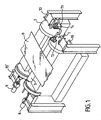
- the device which is the subject of the invention comprises two lateral flanges 1 and 2 designed to receive the bearings of the support rollers 3 and 4 respectively.
- the flanges 1 and 2 are respectively mounted on a central shaft 5 and 6 possibly cooled by water circulation. Trees such as 5 and 6 can be protected for example by a lining of a refractory material allowing avoid the presence of water cooling means. This protection of shafts 5, 6 can be produced using an assembly 7 of ceramic fibers compressed.
- the shafts 5 and 6 of the lateral flanges 1 and 2 are driven in rotation respectively by a motor unit 8, 9, the drive being carried out so as to ensure the synchronization of the angular displacements of the flanges side 1, 2 in order to guarantee the position of the support roller (for example the roller 3 in Figure 1) in the working position.
- the respective bearings of the shafts 5 and 6 of the lateral flanges 1 and 2 are mounted on the frame of the oven, on elements of the latter such as 10 and 10 ', on the on the other side of the oven.
- the tape support rollers 3 and 4 are removably mounted on the corresponding side plates 1 and 2 respectively.
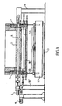
- these flasks have a radial slot or light such as 11, 12 (FIG. 2) intended to respectively receive a bearing from a support roller.
- Each roller bearing supports 3 and 4 is fixed on a counter plate such as 13, 14 using means of suitable fastening, for example by screwing or bolting in order to allow quick and easy disassembly of these bearings.
- Each support roll 3 or 4 is rotated through a drive group such as 15 and a double gimbal transmission system as clearly seen in the figure 3, the rotation of each roller being synchronized with the speed of movement of band B.
- Each of said support rollers 3 and 4 is provided with cooling means, these means can be designed or produced so as to further ensure rapid cooling of said rollers, when these are brought into position low, as will be described below, during their evacuation after the operations of permutation.
- the device further comprises a central liftable buffer 16 making it possible to close off the lower opening provided in the bottom of the oven to ensure the evacuation of a support roll such as 3 or 4 from the oven enclosure to the outside, after a permutation operation, as will be described below.
- the central buffer 16 can be moved in a vertical translational movement using a designated double jack system as a whole by reference 17.
- each lifting buffer such as 18 and 19 is provided with a cylinders 20, 20 'mounted respectively on a carriage 21, 22 moving along of a track 23, 24 respectively.
- the tape support roller in use is the roller 3 supported by the pair of lateral flanges 1.
- the roller 4 supported by the side flanges 2 is in the waiting position.
- the first phase of this permutation operation consists in moving down the central buffer 16 in order to allow the rotation of the lateral flanges 1 and 2. This movement is carried out using the jack systems 17 and in FIG. 2, there is shown in broken lines, the position of the tampon central 16 at the end of this first phase. Then, control groups 8 and 9 synchronized rotation drive side flanges 1 and 2 are set action so as to bring the roller 4 into contact with the strip, this roller being driven in rotation synchronized with the running speed of the tape B. Then, the used roller 3 is moved by the rotation of its support flanges 1 so as to move it away from the strip. Note that during this phase of permutation of support rollers, movement synchronization was ensured angles of the side plates 1, 2 supports of the rollers 3 and 4 in order to guarantee the position of a support roller successively 3 and 4 in the working position.
- the jack system 17 ensures the raising of the central buffer 16 in order to close off the lower opening provided in the bottom of the oven (position in solid lines on the Figure 2) and seal the oven.
- the used roller 3 to be removed then rests on its liftable buffer 18 in the high position, this liftable buffer further ensuring the sealing of the opening of the hearth of the furnace during this phase evacuation of the roller 3.
- the bearings of the roller 3 are then disassembled then the latter is released from the slots 11 provided in its support flanges 1.
- the actuator system 20 is then actuated so as to lower the roller 3 supported by the pad 18, which releases this roller from its flanges 1.
- the used roller is then evacuated outside using the carriage 21 and removed by example using an overhead crane.
- the new roller is therefore positioned on the pad 18 and the carriage is moved 21 along its track 23 so as to bring the roller supported by the pad 18 below the position of the flanges 1 intended to support it.
- the actuator system 20 is then actuated in order to raise the buffer 20 to bring the bearings of the new roller engaged in the slots or radial slots 11 provided in the flanges 1.
- This new roller is ready to be put into service when it has to be swapped with roller 4 currently in service.
- the dashed lines show the rotational movements of the flanges 1 and 2 which are generated during this operation swap at the end of which the new roller positioned on the flanges 1 is put into service and the roller 4, which is then the used roller, is then discharged as described above.
- stamp central 16 can be realized in two independent parts, movable separately, by example using separate cylinders.
Landscapes
- Engineering & Computer Science (AREA)
- Chemical & Material Sciences (AREA)
- Mechanical Engineering (AREA)
- Crystallography & Structural Chemistry (AREA)
- Thermal Sciences (AREA)
- Physics & Mathematics (AREA)
- General Engineering & Computer Science (AREA)
- Materials Engineering (AREA)
- Metallurgy (AREA)
- Organic Chemistry (AREA)
- Heat Treatment Of Strip Materials And Filament Materials (AREA)
- Heat Treatments In General, Especially Conveying And Cooling (AREA)
- Tunnel Furnaces (AREA)
- Closing Of Containers (AREA)
Description
La présente invention concerne un dispositif conçu de façon à assurer le remplacement d'un rouleau support d'une bande, notamment d'une bande d'acier, défilant en continu dans un four de traitement thermique, sans interrompre ce traitement, c'est-à-dire le déplacement de la bande dans le four.The present invention relates to a device designed to ensure the replacement of a support roll for a strip, in particular a steel strip, continuously scrolling through a heat treatment oven, without interrupting treatment, that is to say the movement of the strip in the oven.
On connaít par FR-A-2 540 138 un dispositif permettant de réaliser le remplacement d'un rouleau support de bande par un autre rouleau, dans un four de traitement thermique. Selon ce dispositif antérieur, les deux rouleaux interchangeables sont placés, en position diamétralement opposée, sur la périphérie d'un cylindre monté sur une structure de support, la rotation de ce cylindre autour de son axe permettant de substituer un rouleau à un autre. Cette solution antérieure présente l'inconvénient selon lequel d'une part, lors du changement de rouleau, le cylindre porteur sur lequel s'appuie alors la bande en déplacement peut être difficilement entraíné à la même vitesse de rotation que celle de cette bande, ce qui est susceptible de l'endommager et que d'autre part, il est nécessaire de prévoir des moyens de refroidissement non seulement sur les deux rouleaux interchangeables, mais également sur leur cylindre porteur étant donné que celui-ci vient au contact de la bande en déplacement, lors des opérations de changement de rouleau et qu'en l'absence d'un tel refroidissement, les propriétés de la bande traitée pourraient être altérées. Il résulte de ces inconvénients que cette solution selon la technique antérieure est peu fiable, complexe et donc coûteuse à fabriquer et à entretenir.We know from FR-A-2 540 138 a device for carrying out the replacement of a tape support roller by another roller, in a processing oven thermal. According to this prior device, the two interchangeable rollers are placed, in diametrically opposite position, on the periphery of a mounted cylinder on a support structure, the rotation of this cylinder around its axis allowing to substitute one roll for another. This previous solution presents the disadvantage that on the one hand, when changing the roller, the cylinder carrier on which the moving band then rests can be difficult driven at the same speed of rotation as that of this belt, which is likely to damage it and on the other hand, it is necessary to provide cooling means not only on the two interchangeable rollers, but also on their carrier cylinder since it comes into contact with the moving web, during roll change operations and when in the absence of such cooling, the properties of the treated strip could be altered. It follows from these drawbacks that this solution according to the technique is unreliable, complex and therefore expensive to manufacture and maintain.
En conséquence, la présente invention se propose d'apporter une autre solution au problème consistant, dans un four à traitement thermique de bandes en déplacement continu, à remplacer un rouleau support par un nouveau rouleau, sans interrompre le déplacement de la bande, cette solution nouvelle ne présentant pas les inconvénients du dispositif selon la technique antérieure rappelée ci-dessus. Consequently, the present invention proposes to provide another solution to the problem consisting, in a heat treatment furnace of strips of continuous movement, replacing a support roller with a new roller, without interrupt the movement of the strip, this new solution not presenting the disadvantages of the device according to the prior art recalled above.
Cette invention a donc pour objet un dispositif destiné à assurer le remplacement d'un rouleau support d'une bande, notamment une bande d'acier, défilant en continu dans un four de traitement thermique, sans interruption du processus de traitement, par permutation avec un second rouleau, identique, disposé en position d'attente, ladite bande étant toujours supportée par au moins l'un desdits rouleaux lors des opérations de permutation, ce dispositif étant caractérisé en ce qu'il comprend :
- deux paires de flasques latéraux, montés respectivement à rotation sur un arbre tourillonnant dans le châssis du four, chaque paire de flasques recevant un rouleau de support de bande par l'intermédiaire de moyens de fixation amovibles ;
- des moyens d'entraínement desdites paires de flasques latéraux assurant la synchronisation de leur déplacement angulaire lors des opérations de permutation ;
- un tampon central pourvu de moyens de relevage conçu de façon à réaliser l'obturation de l'ouverture prévue dans la sole du four en vue d'effectuer les opérations d'évacuation d'un rouleau, de l'enceinte du four, vers l'extérieur, à l'issue d'une opération de permutation ;
- deux tampons relevables, un pour chaque rouleau support, pouvant être déplacés,
par exemple à l'aide d'un système de vérins selon un mouvement de translation
vertical pour respectivement :
- assurer l'étanchéité de l'ouverture prévue dans la sole du four lors de la phase de permutation de rouleaux ;
- assurer le support des rouleaux lors du démontage des paliers de rouleaux pour enlever le rouleau hors service des flasques correspondants et,
- réaliser la descente du rouleau hors service afin de le dégager de ses flasques ;
- deux chariots mobiles transversalement à l'axe du four sur lesquels sont respectivement montés lesdits tampons relevables et leur système de relevage, lesdits chariots se déplaçant le long de voies de roulement de manière à assurer le déplacement du rouleau hors service hors du four pour son évacuation hors du four et la mise en place d'un rouleau neuf et,
- un groupe d'entraínement pour chacun des rouleaux supports, de manière à réaliser une rotation de chaque rouleau synchronisée avec la vitesse de défilement de la bande.
- two pairs of lateral flanges, respectively mounted for rotation on a spindle shaft in the frame of the oven, each pair of flanges receiving a strip support roller by means of removable fixing means;
- means for driving said pairs of lateral flanges ensuring the synchronization of their angular displacement during the permutation operations;
- a central pad provided with lifting means designed so as to close off the opening provided in the floor of the oven in order to carry out the operations of removing a roll from the oven enclosure, towards the outside, after a permutation operation;
- two lifting pads, one for each support roller, which can be moved, for example using a system of jacks according to a vertical translational movement for respectively:
- sealing the opening provided in the hearth of the oven during the rollover phase;
- ensure the support of the rollers when dismantling the roller bearings to remove the out-of-service roller from the corresponding flanges and,
- lower the roll out of service in order to free it from its flanges;
- two movable carriages transversely to the axis of the oven on which said liftable pads and their lifting system are respectively mounted, said carriages moving along rolling tracks so as to ensure the displacement of the roll out of service out of the oven for its evacuation out of the oven and the installation of a new roller and,
- a drive group for each of the support rollers, so as to rotate each roller synchronized with the running speed of the strip.
Selon une caractéristique de la présente invention, chacun desdits rouleaux supports est pourvu de moyens de refroidissement, ces moyens pouvant être conçus de manière à assurer en outre un refroidissement rapide desdits rouleaux, en position basse, lors de leur évacuation après les opérations de permutation.According to a characteristic of the present invention, each of said rollers supports is provided with cooling means, these means being able to be designed so as to further ensure rapid cooling of said rollers, low position, when evacuated after swapping operations.
Selon une autre caractéristique de la présente invention, chaque rouleau support est monté sur ses flasques par l'intermédiaire d'une lumière ou fente radiale prévue sur chacun desdits flasques en vue de recevoir le palier support de rouleau correspondant et les moyens assurant la fixation amovible de chaque rouleau support sur ses flasques sont réalisés sous la forme de contre plaques sur lesquelles sont montés respectivement lesdits paliers, ces contre plaques étant par exemple vissées ou boulonnées sur lesdits flasques.According to another characteristic of the present invention, each support roller is mounted on its flanges by means of a radial slot or slot provided on each of said flanges for receiving the roller support bearing corresponding and the means ensuring the removable fixing of each roller support on its flanges are made in the form of counter plates on which are respectively mounted said bearings, these against plates being by example screwed or bolted to said flanges.
Selon une autre caractéristique de l'invention, l'axe sur lequel tourillonne chacun desdits flasques est refroidi à l'eau. Afin d'éviter des moyens de refroidissement par circulation d'eau, ledit axe peut être protégé par un garnissage en un matériau réfractaire, pouvant être réalisé par exemple sous la forme d'un assemblage de fibres céramiques comprimées.According to another characteristic of the invention, the axis on which each pivots of said flanges is cooled with water. In order to avoid means of cooling by water circulation, said axis can be protected by a lining of a material refractory, which can be produced for example in the form of an assembly of compressed ceramic fibers.
Selon la présente invention, ledit tampon central peut être réalisé en deux parties pourvues chacune de moyens de déplacement permettant d'assurer leur relevage séparément l'une de l'autre.According to the present invention, said central buffer can be produced in two parts each provided with displacement means making it possible to lift them separately from each other.
D'autres caractéristiques et avantages de la présente invention ressortiront de la description faite ci-après en référence aux dessins annexés qui en illustrent un exemple de réalisation dépourvu de tout caractère limitatif.Other characteristics and advantages of the present invention will emerge from the description given below with reference to the accompanying drawings which illustrate one exemplary embodiment devoid of any limiting character.
Sur les dessins :
- La figure 1 est une vue schématique représentant en perspective le dispositif selon la présente invention ;
- La figure 2 est une vue en élévation frontale du dispositif selon l'invention et,
- La figure 3 est une vue en coupe selon III-III de la figure 2.
- Figure 1 is a schematic view showing in perspective the device according to the present invention;
- FIG. 2 is a front elevation view of the device according to the invention and,
- Figure 3 is a sectional view along III-III of Figure 2.
Ainsi qu'on la précisé dans le préambule de la présente description, le dispositif de la présente invention est conçu de façon à assurer en permanence la qualité du guidage de la bande dans le four, sans dégradation de ce guidage ou de la qualité du produit pendant l'opération de permutation du rouleau support de bande. Dans ce but, un rouleau doit pouvoir être remplacé sans arrêter le défilement de la bande par permutation avec un second rouleau, identique, disposé dans une position d'attente, la bande étant toujours supportée par au moins un rouleau pendant les opérations de permutation et de démontage du rouleau devant être mis hors service, le rouleau support en service étant toujours entrainé en rotation en synchronisme avec la vitesse de défilement de la bande.As specified in the preamble to this description, the device the present invention is designed so as to permanently ensure the quality of the guidance of the strip in the oven, without degradation of this guidance or of the quality of the product during the swap operation of the tape support roller. In this purpose, a roll must be able to be replaced without stopping the running of the strip by swapping with a second identical roller arranged in a waiting position, the strip always being supported by at least one roller during the operations to swap and disassemble the roller to be taken out of service, the roller support in service being always rotated in synchronism with the tape running speed.
Dans ce but, le dispositif objet de l'invention comporte deux flasques latéraux 1 et 2
conçus de façon à recevoir respectivement les paliers des rouleaux supports 3 et 4.
Les flasques 1 et 2 sont respectivement montés sur un arbre central 5 et 6
éventuellement refroidi par circulation d'eau. Les arbres tels que 5 et 6 peuvent être
protégés par exemple par un garnissage d'un matériau réfractaire permettant
d'éviter la présence de moyens de refroidissement à l'eau. Cette protection des
arbres 5, 6 peut être réalisée à l'aide d'un assemblage 7 de fibres céramiques
comprimées. Les arbres 5 et 6 des flasques latéraux 1 et 2 sont entraínés en
rotation respectivement par un groupe moteur 8, 9, l'entraínement étant réalisé de
façon à assurer la synchronisation des déplacements angulaires des flasques
latéraux 1, 2 afin de garantir la position du rouleau support (par exemple le rouleau
3 sur la figure 1) en position de travail.To this end, the device which is the subject of the invention comprises two lateral flanges 1 and 2
designed to receive the bearings of the
Les paliers respectifs des arbres 5 et 6 des flasques latéraux 1 et 2 sont montés sur
le châssis du four, sur des éléments de ce dernier tels que 10 et 10', de part et
d'autre du four.The respective bearings of the
Les rouleaux supports de bande 3 et 4 sont montés de façon amovible sur les
flasques latéraux correspondants 1 et 2 respectivement. Dans ce but, ces flasques
comportent une fente ou lumière radiale telle que 11, 12 (figure 2) destinée à
recevoir respectivement un palier d'un rouleau support. Chaque palier de rouleaux
supports 3 et 4 est fixé sur une contre plaque telle que 13, 14 à l'aide de moyens de
fixation appropriés, par exemple par vissage ou boulonnage afin de permettre un
démontage facile et rapide de ces paliers. Chaque rouleau support 3 ou 4 est
entraíné en rotation par l'intermédiaire d'un groupe d'entraínement tel que 15 et d'un
système de transmission à double cardans comme on le voit claiement sur la figure
3, la rotation de chaque rouleau étant synchronisée avec la vitesse de déplacement
de la bande B.The
Chacun desdits rouleaux supports 3 et 4 est pourvu de moyens de refroidissement,
ces moyens pouvant être conçus ou réalisés de manière à assurer en outre un
refroidissement rapide desdits rouleaux, lorsque ceux-ci sont amenés en position
basse, comme on le décrira ci-après, lors de leur évacuation après les opérations de
permutation.Each of said
Le dispositif comporte en outre un tampon central relevable 16 permettant d'obturer
l'ouverture inférieure prévue dans la sole du four afin d'assurer l'évacuation d'un
rouleau support tel que 3 ou 4 de l'enceinte du four vers l'extérieur, à l'issue d'une
opération de permutation, comme on le décrira ci-après. Dans l'exemple de
réalisation illustré par la figure 2, le tampon central 16 peut être déplacé selon un
mouvement de translation vertical à l'aide d'un système de double vérins désigné
dans son ensemble par la référence 17.The device further comprises a central
Par ailleurs, l'invention prévoit sous chaque flasque latéral 1 et 2, un tampon relevable respectivement 18 et 19. Les fonctions de chacun desdits tampons relevables sont les suivantes :
- assurer l'étanchéité de l'ouverture prévue dans la sole du four lors des opérations de permutation de rouleau support ;
- supporter un nouveau rouleau devant être positionné sur ses flasques latéraux lors d'un remplacement de rouleau ou supporter un rouleau usagé afin de permettre le démontage de ses paliers avant son évacuation, après une opération de permutation et,
- assurer la descente du rouleau usagé pour le dégager de ses flasques de support ou assurer la montée d'un rouleau neuf pour engager ses paliers sur les lumères ou fentes prévues à cet effet sur ses flasques de support.
- sealing the opening provided in the bottom of the oven during the permutation operations of the support roller;
- support a new roller to be positioned on its side flanges during a roller replacement or support a used roller to allow disassembly of its bearings before its evacuation, after a permutation operation and,
- ensure the descent of the used roller to release it from its support flanges or ensure the rise of a new roller to engage its bearings on the lumens or slots provided for this purpose on its support flanges.
Dans ce but, chaque tampon relevable tels que 18 et 19 est muni d'un système de
vérins 20, 20' montés respectivement sur un chariot 21, 22 se déplaçant le long
d'une voie de roulement 23, 24 respectivement.For this purpose, each lifting buffer such as 18 and 19 is provided with a
Le fonctionnement du dispositif selon l'invention est le suivant :The operation of the device according to the invention is as follows:
En se référant à la figure 2, on voit que le rouleau support de bande en service est
le rouleau 3 supporté par la paire de flasques latéraux 1. Le rouleau 4 supporté par
les flasques latéraux 2 est en position d'attente.Referring to FIG. 2, it can be seen that the tape support roller in use is
the
Lorsque le rouleau 3 est usé, il convient d'effectuer sa permutation avec le rouleau
neuf 4 en position d'attente. La première phase de cette opération de permutation
consiste à déplacer vers le bas le tampon central 16 afin de permettre la rotation des
flasques latéraux 1 et 2. Ce déplacement s'effectue à l'aide des systèmes de vérins
17 et sur la figure 2, on a représenté en traits interrompus, la position du tampon
central 16 à l'issue de cette première phase. Puis, les groupes de commande 8 et 9
d'entraínement en rotation synchronisée des flasques latéraux 1 et 2 sont mis en
action de manière à amener le rouleau 4 au contact de la bande, ce rouleau étant
entraíné en rotation synchronisée avec la vitesse de défilement de la bande B.
Ensuite, le rouleau usagé 3 est déplacé par la rotation de ses flasques de support 1
de manière à l'éloigner de la bande. On notera que lors de cette phase de
permutation de rouleaux supports, on a assuré la synchronisation des déplacements
angulaires des flasques latéraux 1, 2 supports des rouleaux 3 et 4 afin de garantir la
position d'un rouleau support successivement 3 et 4 en position de travail. When the
Il convient maintenant de réaliser la sortie du rouleau usagé 3 et son remplacement
par un rouleau neuf.Now take out the used
Le système de vérin 17 assure le relevage du tampon central 16 afin d'obturer
l'ouverture inférieure prévue dans la sole du four (position en traits pleins sur la
figure 2) et assurer l'étanchéité du four. Le rouleau usagé 3 devant être évacué
repose alors sur son tampon relevable 18 en position haute, ce tampon relevable
assurant en outre l'étanchéité de l'ouverture de la sole du four durant cette phase
d'évacuation du rouleau 3. On réalise alors le démontage des paliers du rouleau 3
puis on dégage ce dernier des fentes 11 prévues dans ses flasques de support 1.
On actionne ensuite le système de vérins 20 de façon à assurer la descente du
rouleau 3 supporté par le tampon 18, ce qui dégage ce rouleau de ses flasques 1.
Le rouleau usagé est ensuite évacué à l'extérieur à l'aide du chariot 21 et enlevé par
exemple à l'aide d'un pont roulant.The
Il convient ensuite de mettre en place un nouveau rouleau sur le tampon 18 libéré
du rouleau usagé 3.It is then necessary to place a new roller on the released
Le nouveau rouleau est donc positionné sur le tampon 18 et l'on déplace le chariot
21 le long de sa voie de roulement 23 de manière à amener le rouleau supporté par
le tampon 18 en dessous de la position des flasques 1 destinés à le supporter . Le
système de vérins 20 est alors actionné afin de relever le tampon 20 pour amener
les paliers du nouveau rouleau en prise dans les fentes ou lumières radiales 11
prévues dans les flasques1. On fixe ensuite les contre plaques telles que 13
assurant le maintien des paliers du nouveau rouleau sur les flasques 1. Ce nouveau
rouleau est prêt à être mis en service lorsqu'il devra être permuté avec le rouleau 4
actuellement en service. Sur la figure 2, on a représenté en traits mixtes, les
mouvements de rotation des flasques 1 et 2 qui sont générés lors de cette opération
de permutation à l'issue de laquelle le nouveau rouleau positionné sur les flasques 1
est mis en service et le rouleau 4, qui est alors le rouleau usagé, est ensuite évacué
comme décrit ci-dessus. The new roller is therefore positioned on the
La lecture de la description qui précède, fait clairement ressortir les avantages
apportés par le dispositif objet de l'invention notamment celui selon lequel on assure
en permanence la qualité du guidage de la bande dans le four, cette bande étant
toujours supportée par un rouleau dont la rotation est toujours synchronisée avec sa
vitesse de défilement. Par ailleurs, les opérations de permutation de rouleaux
s' effectuent de façon simple sans altérer l'étanchéité du four, grâce aux moyens
prévus par l'invention (tampons 18 et 19 et tampon central 16) pour maintenir cette
étanchéité.Reading the above description clearly highlights the advantages
provided by the device which is the subject of the invention, in particular that according to which
permanently the quality of the guide of the strip in the oven, this strip being
always supported by a roller whose rotation is always synchronized with its
scrolling speed. In addition, the rollover operations
are done in a simple way without altering the tightness of the oven, thanks to the means
provided by the invention (
Il demeure bien entendu que la présente invention n'est pas limitée aux exemples de réalisation décrits et/ou représentés mais qu'elle en englobe toutes les variantes qui entrent dans le cadre de la portée des revendications annexées. Ainsi, le tampon central 16 peut être réalisé en deux parties indépendantes, mobiles séparément, par exemple à l'aide de vérins distincts.It remains to be understood that the present invention is not limited to the examples of realization described and / or represented but that it includes all the variants which fall within the scope of the appended claims. So the stamp central 16 can be realized in two independent parts, movable separately, by example using separate cylinders.
Claims (10)
- Device for ensuring the replacement of a support roller for a band, particularly a steel band, running continuously in a heat treatment furnace, without interrupting the treatment process, by interchanging with a second, identical roller, located in a waiting position, said band being still supported by at least one of said rollers during the interchange operations, said device being characterized in that it comprises:two pairs of lateral flanges (1, 2), mounted respectively in rotary manner on a shaft (5, 6) pivoting in the furnace frame, each pair of flanges receiving a band support roller (3, 4) by means of detachable fixing means (13, 14),means (8, 9) for driving said pairs of lateral flanges ensuring the synchronization of their angular displacement during the interchange operations,a central plug (16) equipped with lifting means (17) in order to seal the opening provided in the furnace hearth in order to perform the operations of discharging a roller from the furnace enclosure to the outside, following an interchange operation,two raisable plugs (18, 19), one for each support roller, which can be given a vertical translatory movement in order to respectively:ensure the sealing of the opening provided in the furnace hearth during the roller interchange phase,ensure the support of the rollers during the dismantling of roller bearings in order to remove the out of use roller from the corresponding flanges andlower the out of use roller in order to free it from its flanges,two carriages (21, 22) movable transversely to the furnace axis and on which are respectively installed said raisable plugs (18, 19) and their raising system, said carriages moving along runways so as to ensure the displacement of the out of use roller for the discharge thereof from the furnace and the putting into place of a new roller anda drive group for each support roller (3, 4), so as to obtain a rotation of each roller synchronized with the running speed of the band (B).
- Device according to claim 1, characterized in that each of said support rollers (3, 4) is provided with cooling means.
- Device according to claim 2, characterized in that said cooling means are designed so as to also ensure a rapid cooling of said rollers, in the bottom position, during their discharge following the interchange operations.
- Device according to any one of the preceding claims, characterized in that each support roller (3, 4) is mounted on its flanges (1, 2) by means of a radial slot or opening (11, 12) provided on each of said flanges, with a view to receiving the corresponding support roller bearing.
- Device according to any one of the preceding claims, characterized in that the means ensuring the detachable fixing of each support roller (3, 4) to its flanges (1, 2) are in the form of counterplates (13, 14), on which are respectively mounted the bearings of said rollers, said counterplates being screwed to said flanges.
- Device according to any one of the preceding claims, characterized in that the shaft (5, 6) on which respectively pivots each of said flanges (1, 2) is cooled with water.
- Device according to any one of the preceding claims, characterized in that the shaft (5, 6), on which respectively pivots each of said flanges (1, 2) is protected by a refractory material lining.
- Device according to claim 7, characterized in that said lining is in the form of a compressed ceramic fibre assembly (7).
- Device according to any one of the preceding claims, characterized in that the means ensuring the raising and lowering of on the one hand the plugs (18, 19) and the central plug (16) are in the form of jack systems (20, 17).
- Device according to any one of the preceding claims, characterized in that the central plug is in two parts, each having displacement means permitting the separate raising thereof, during the roller interchange operations.
Applications Claiming Priority (2)
| Application Number | Priority Date | Filing Date | Title |
|---|---|---|---|
| FR9702365 | 1997-02-27 | ||
| FR9702365A FR2760077B1 (en) | 1997-02-27 | 1997-02-27 | DEVICE FOR ENSURING THE REPLACEMENT OF A TAPE SUPPORT ROLLER IN A HEAT TREATMENT OVEN |
Publications (2)
| Publication Number | Publication Date |
|---|---|
| EP0862033A1 EP0862033A1 (en) | 1998-09-02 |
| EP0862033B1 true EP0862033B1 (en) | 2002-11-13 |
Family
ID=9504256
Family Applications (1)
| Application Number | Title | Priority Date | Filing Date |
|---|---|---|---|
| EP98400333A Expired - Lifetime EP0862033B1 (en) | 1997-02-27 | 1998-02-12 | Device for the replacement of a band support roller in a heating furnace |
Country Status (6)
| Country | Link |
|---|---|
| US (1) | US5938431A (en) |
| EP (1) | EP0862033B1 (en) |
| JP (1) | JPH10306323A (en) |
| DE (2) | DE862033T1 (en) |
| ES (1) | ES2119734T3 (en) |
| FR (1) | FR2760077B1 (en) |
Cited By (1)
| Publication number | Priority date | Publication date | Assignee | Title |
|---|---|---|---|---|
| CN110494572A (en) * | 2017-04-13 | 2019-11-22 | 杰富意钢铁株式会社 | Sealing device |
Families Citing this family (7)
| Publication number | Priority date | Publication date | Assignee | Title |
|---|---|---|---|---|
| NL1010971C2 (en) | 1999-01-06 | 2000-07-07 | Thermtec B V | Belt guiding device with coolants. |
| FI109363B (en) * | 1999-08-04 | 2002-07-15 | Outokumpu Oy | Device in continuous heat treatment chutes to support material to be treated |
| JP4564197B2 (en) * | 2001-03-27 | 2010-10-20 | 中外炉工業株式会社 | Catenary-type continuous heat treatment furnace roll changer |
| JP4514019B2 (en) * | 2003-12-02 | 2010-07-28 | 株式会社不二越 | Hearth roller device and roller hearth furnace |
| JP5038386B2 (en) * | 2009-12-18 | 2012-10-03 | 中外炉工業株式会社 | Catenary furnace |
| DE102011079771B4 (en) | 2011-07-25 | 2016-12-01 | Ebner Industrieofenbau Gmbh | Roller changing device and method for changing a roller for ovens |
| CN109926895B (en) * | 2019-02-28 | 2021-03-09 | 北京首钢股份有限公司 | Online grinding control method and device for furnace roller in annealing furnace |
Family Cites Families (5)
| Publication number | Priority date | Publication date | Assignee | Title |
|---|---|---|---|---|
| US4049372A (en) * | 1976-05-04 | 1977-09-20 | Allegheny Ludlum Industries, Inc. | Apparatus for supporting and removing a work supporting roll |
| DE3004805C2 (en) * | 1980-02-09 | 1981-12-10 | Sundwiger Eisenhütte Maschinenfabrik Grah & Co, 5870 Hemer | Method and device for replacing support rollers in roller hearth continuous annealing furnaces |
| DE3230115A1 (en) * | 1982-08-13 | 1984-02-16 | Ruhrgas Ag, 4300 Essen | METHOD FOR REPLACING THE ROLLS OF A CONTINUOUS ROLLER OVEN AND OVEN FOR CARRYING OUT THE METHOD |
| FI67726C (en) * | 1983-01-27 | 1985-05-10 | Outokumpu Oy | ANORDNING FOER UPPBAERANDE AV FOER BEHANDLING AVSETT MATERIAL VID KONTINUERLIGT ARBETANDE VAERMEBEHANDLINGSUGNAR |
| DE3735542A1 (en) * | 1987-10-21 | 1989-05-03 | Zimmermann & Jansen Gmbh | ROLLER GEAR FOR THE TRANSPORT OF FLAT GLASS |
-
1997
- 1997-02-27 FR FR9702365A patent/FR2760077B1/en not_active Expired - Lifetime
-
1998
- 1998-02-12 EP EP98400333A patent/EP0862033B1/en not_active Expired - Lifetime
- 1998-02-12 ES ES98400333T patent/ES2119734T3/en not_active Expired - Lifetime
- 1998-02-12 DE DE0862033T patent/DE862033T1/en active Pending
- 1998-02-12 DE DE69809312T patent/DE69809312T2/en not_active Expired - Lifetime
- 1998-02-26 US US09/030,960 patent/US5938431A/en not_active Expired - Lifetime
- 1998-02-27 JP JP10046640A patent/JPH10306323A/en active Pending
Cited By (2)
| Publication number | Priority date | Publication date | Assignee | Title |
|---|---|---|---|---|
| CN110494572A (en) * | 2017-04-13 | 2019-11-22 | 杰富意钢铁株式会社 | Sealing device |
| US11401575B2 (en) | 2017-04-13 | 2022-08-02 | Jfe Steel Corporation | Sealing device |
Also Published As
| Publication number | Publication date |
|---|---|
| ES2119734T3 (en) | 2003-03-01 |
| DE862033T1 (en) | 1999-05-06 |
| FR2760077B1 (en) | 1999-04-30 |
| ES2119734T1 (en) | 1998-10-16 |
| FR2760077A1 (en) | 1998-08-28 |
| JPH10306323A (en) | 1998-11-17 |
| US5938431A (en) | 1999-08-17 |
| DE69809312T2 (en) | 2003-09-04 |
| EP0862033A1 (en) | 1998-09-02 |
| DE69809312D1 (en) | 2002-12-19 |
Similar Documents
| Publication | Publication Date | Title |
|---|---|---|
| EP0862033B1 (en) | Device for the replacement of a band support roller in a heating furnace | |
| FR2718995A1 (en) | Printing machine. | |
| EP0095423A1 (en) | Variable-size offset printing apparatus | |
| CH663381A5 (en) | DEVICE FOR REPLACING PLATE HOLDER CYLINDERS. | |
| CA2164046C (en) | Lateral support device for the continuous casting of metallic strips between cylinders | |
| EP0908246A1 (en) | Work rolls or intermediate rolls changing device of roll stands and stocking device | |
| FR3055012A1 (en) | METHOD AND DEVICE FOR EXCHANGING THE EXTRACTION ROLLS IN AN EXIT SAS OF A TIN BATH WITH A CONTINUOUS SUPPORT OF THE FLOATING GLASS RIBBON | |
| NL7906942A (en) | APPARATUS AND METHOD FOR TREATING UNVULLCANIZED TIRES. | |
| FR2601667A1 (en) | POSITIONING GLASS PLATES FOR BODY | |
| EP0928682B1 (en) | Device for the mecanical treatment of paper which has an improved support for a roller and method for exchanging the roller in such a device | |
| FR2509701A1 (en) | DEVICE FOR RECOVERING, TRANSPORTING AND EXHAUSTING IN A COOLING DEVICE FOR PLASTIC MOLDED BODIES, PARTICULARLY FOR CARBON ANODES | |
| FR2660295A1 (en) | DEVICE FOR TRANSFERRING, IN PARTICULAR, HOLLOW BODIES LIKE TUBES OR BOXES, FROM A MEANS OF TRANSPORT TO ANOTHER MEANS OF TRANSPORT MOVING AT A DIFFERENT SPEED. | |
| CA2160479A1 (en) | Device for releasing a product from a continuously circulating belt | |
| FR2639581A1 (en) | PRINTING GROUP CARRIAGE FOR A PRINTING STATION IN ROTARY MACHINES | |
| EP0453329B1 (en) | Device for fastening the unloading and transfer of steel work products | |
| FR2492284A1 (en) | ROLLER FOR STEEL TUBES | |
| DK171912B1 (en) | Rolling mill with a continuous grinding of the areas of grinding surfaces exposed to least wear | |
| EP0560662B1 (en) | Method and installation for rolling a metal plate | |
| FR2895305A1 (en) | PRINTING PRESS WITH ENHANCED BAND COMMITMENT AND METHOD OF ENGAGING CORRESPONDING BAND. | |
| JPH04270043A (en) | Device for removing torch drop in cast billet for beam blank | |
| US4879846A (en) | Ingot knock out and grind machine | |
| FR2509202A1 (en) | STEEL TUBE ROLLER COMPRISING A DEVICE FOR CHANGING THE CYLINDERS | |
| CN222960592U (en) | Bearing processing conveying device | |
| GB2124949A (en) | Apparatus for supporting opposing guide-shoes in a piercing or elongating rolling mill | |
| FR3159541A1 (en) | Rolling tool for circular rolling mill, circular rolling mill comprising such a tool, rolling method using such a rolling mill and method of maintaining such a rolling mill |
Legal Events
| Date | Code | Title | Description |
|---|---|---|---|
| PUAI | Public reference made under article 153(3) epc to a published international application that has entered the european phase |
Free format text: ORIGINAL CODE: 0009012 |
|
| AK | Designated contracting states |
Kind code of ref document: A1 Designated state(s): DE ES GB IT NL SE |
|
| AX | Request for extension of the european patent |
Free format text: AL;LT;LV;MK;RO;SI |
|
| GBC | Gb: translation of claims filed (gb section 78(7)/1977) | ||
| REG | Reference to a national code |
Ref country code: ES Ref legal event code: BA2A Ref document number: 2119734 Country of ref document: ES Kind code of ref document: T1 |
|
| TCNL | Nl: translation of patent claims filed | ||
| 17P | Request for examination filed |
Effective date: 19980912 |
|
| DET | De: translation of patent claims | ||
| AKX | Designation fees paid |
Free format text: DE ES GB IT NL SE |
|
| RBV | Designated contracting states (corrected) |
Designated state(s): DE ES GB IT NL SE |
|
| GRAG | Despatch of communication of intention to grant |
Free format text: ORIGINAL CODE: EPIDOS AGRA |
|
| GRAG | Despatch of communication of intention to grant |
Free format text: ORIGINAL CODE: EPIDOS AGRA |
|
| GRAH | Despatch of communication of intention to grant a patent |
Free format text: ORIGINAL CODE: EPIDOS IGRA |
|
| 17Q | First examination report despatched |
Effective date: 20020521 |
|
| GRAH | Despatch of communication of intention to grant a patent |
Free format text: ORIGINAL CODE: EPIDOS IGRA |
|
| GRAA | (expected) grant |
Free format text: ORIGINAL CODE: 0009210 |
|
| AK | Designated contracting states |
Kind code of ref document: B1 Designated state(s): DE ES GB IT NL SE |
|
| REG | Reference to a national code |
Ref country code: GB Ref legal event code: FG4D Free format text: NOT ENGLISH |
|
| REF | Corresponds to: |
Ref document number: 69809312 Country of ref document: DE Date of ref document: 20021219 |
|
| GBT | Gb: translation of ep patent filed (gb section 77(6)(a)/1977) |
Effective date: 20030108 |
|
| REG | Reference to a national code |
Ref country code: ES Ref legal event code: FG2A Ref document number: 2119734 Country of ref document: ES Kind code of ref document: T3 |
|
| PLBE | No opposition filed within time limit |
Free format text: ORIGINAL CODE: 0009261 |
|
| STAA | Information on the status of an ep patent application or granted ep patent |
Free format text: STATUS: NO OPPOSITION FILED WITHIN TIME LIMIT |
|
| 26N | No opposition filed |
Effective date: 20030814 |
|
| PGFP | Annual fee paid to national office [announced via postgrant information from national office to epo] |
Ref country code: GB Payment date: 20050202 Year of fee payment: 8 |
|
| PGFP | Annual fee paid to national office [announced via postgrant information from national office to epo] |
Ref country code: NL Payment date: 20050214 Year of fee payment: 8 |
|
| PG25 | Lapsed in a contracting state [announced via postgrant information from national office to epo] |
Ref country code: GB Free format text: LAPSE BECAUSE OF NON-PAYMENT OF DUE FEES Effective date: 20060212 |
|
| PGFP | Annual fee paid to national office [announced via postgrant information from national office to epo] |
Ref country code: IT Payment date: 20060228 Year of fee payment: 9 |
|
| PG25 | Lapsed in a contracting state [announced via postgrant information from national office to epo] |
Ref country code: NL Free format text: LAPSE BECAUSE OF NON-PAYMENT OF DUE FEES Effective date: 20060901 |
|
| GBPC | Gb: european patent ceased through non-payment of renewal fee |
Effective date: 20060212 |
|
| NLV4 | Nl: lapsed or anulled due to non-payment of the annual fee |
Effective date: 20060901 |
|
| PG25 | Lapsed in a contracting state [announced via postgrant information from national office to epo] |
Ref country code: IT Free format text: LAPSE BECAUSE OF NON-PAYMENT OF DUE FEES Effective date: 20070212 |
|
| PGFP | Annual fee paid to national office [announced via postgrant information from national office to epo] |
Ref country code: SE Payment date: 20130130 Year of fee payment: 16 Ref country code: ES Payment date: 20130207 Year of fee payment: 16 Ref country code: DE Payment date: 20130124 Year of fee payment: 16 |
|
| REG | Reference to a national code |
Ref country code: DE Ref legal event code: R119 Ref document number: 69809312 Country of ref document: DE |
|
| REG | Reference to a national code |
Ref country code: SE Ref legal event code: EUG |
|
| PG25 | Lapsed in a contracting state [announced via postgrant information from national office to epo] |
Ref country code: SE Free format text: LAPSE BECAUSE OF NON-PAYMENT OF DUE FEES Effective date: 20140213 |
|
| REG | Reference to a national code |
Ref country code: DE Ref legal event code: R119 Ref document number: 69809312 Country of ref document: DE Effective date: 20140902 |
|
| PG25 | Lapsed in a contracting state [announced via postgrant information from national office to epo] |
Ref country code: DE Free format text: LAPSE BECAUSE OF NON-PAYMENT OF DUE FEES Effective date: 20140902 |
|
| REG | Reference to a national code |
Ref country code: ES Ref legal event code: FD2A Effective date: 20150406 |
|
| PG25 | Lapsed in a contracting state [announced via postgrant information from national office to epo] |
Ref country code: ES Free format text: LAPSE BECAUSE OF NON-PAYMENT OF DUE FEES Effective date: 20140213 |