EP0862009B1 - Releasable plug in coupling - Google Patents
Releasable plug in coupling Download PDFInfo
- Publication number
- EP0862009B1 EP0862009B1 EP98102351A EP98102351A EP0862009B1 EP 0862009 B1 EP0862009 B1 EP 0862009B1 EP 98102351 A EP98102351 A EP 98102351A EP 98102351 A EP98102351 A EP 98102351A EP 0862009 B1 EP0862009 B1 EP 0862009B1
- Authority
- EP
- European Patent Office
- Prior art keywords
- indicator member
- housing wall
- plug
- opening
- holding rib
- Prior art date
- Legal status (The legal status is an assumption and is not a legal conclusion. Google has not performed a legal analysis and makes no representation as to the accuracy of the status listed.)
- Expired - Lifetime
Links
Images

Classifications
-
- F—MECHANICAL ENGINEERING; LIGHTING; HEATING; WEAPONS; BLASTING
- F16—ENGINEERING ELEMENTS AND UNITS; GENERAL MEASURES FOR PRODUCING AND MAINTAINING EFFECTIVE FUNCTIONING OF MACHINES OR INSTALLATIONS; THERMAL INSULATION IN GENERAL
- F16L—PIPES; JOINTS OR FITTINGS FOR PIPES; SUPPORTS FOR PIPES, CABLES OR PROTECTIVE TUBING; MEANS FOR THERMAL INSULATION IN GENERAL
- F16L37/00—Couplings of the quick-acting type
- F16L37/08—Couplings of the quick-acting type in which the connection between abutting or axially overlapping ends is maintained by locking members
- F16L37/084—Couplings of the quick-acting type in which the connection between abutting or axially overlapping ends is maintained by locking members combined with automatic locking
- F16L37/0841—Couplings of the quick-acting type in which the connection between abutting or axially overlapping ends is maintained by locking members combined with automatic locking by means of a transversally slidable locking member surrounding the tube
-
- F—MECHANICAL ENGINEERING; LIGHTING; HEATING; WEAPONS; BLASTING
- F16—ENGINEERING ELEMENTS AND UNITS; GENERAL MEASURES FOR PRODUCING AND MAINTAINING EFFECTIVE FUNCTIONING OF MACHINES OR INSTALLATIONS; THERMAL INSULATION IN GENERAL
- F16L—PIPES; JOINTS OR FITTINGS FOR PIPES; SUPPORTS FOR PIPES, CABLES OR PROTECTIVE TUBING; MEANS FOR THERMAL INSULATION IN GENERAL
- F16L2201/00—Special arrangements for pipe couplings
- F16L2201/10—Indicators for correct coupling
-
- Y—GENERAL TAGGING OF NEW TECHNOLOGICAL DEVELOPMENTS; GENERAL TAGGING OF CROSS-SECTIONAL TECHNOLOGIES SPANNING OVER SEVERAL SECTIONS OF THE IPC; TECHNICAL SUBJECTS COVERED BY FORMER USPC CROSS-REFERENCE ART COLLECTIONS [XRACs] AND DIGESTS
- Y10—TECHNICAL SUBJECTS COVERED BY FORMER USPC
- Y10S—TECHNICAL SUBJECTS COVERED BY FORMER USPC CROSS-REFERENCE ART COLLECTIONS [XRACs] AND DIGESTS
- Y10S285/00—Pipe joints or couplings
- Y10S285/921—Snap-fit
Description
Die Erfindung bezieht sich auf eine lösbare Steckverbindung mit Montageanzeige zum Verbinden von Leitungen für flüssige und gasförmige Stoffe nach dem Oberbegriff des Anspruchs 1.The invention relates to a detachable connector with a display for connecting pipes for liquid and gaseous substances after the Preamble of claim 1.
Bei einer durch die EP 0 505 930 B1 bekannten Steckverbindung dieser Art besteht das Anzeigeteil aus zwei an einem Flaggenteil gabelförmig angeformten, zueinander parallelen Stegen, welche in zwei gegenüberliegende Seitenschlitze der Gehäusewand tangential einführbar sind und im Aufnahmebereich der Halterippe zwei nach innen abstehende Ohren aufweisen, welche beim Einführen des Einsteckteils von der Halterippe nach außen weggedrückt werden. Die Ohren weisen ferner zum Gabelbügel hin jeweils einen Rasthaken auf, welche im eingesteckten Zustand des Anzeigeteils am Ende des Seitenschlitzes verhaken. Sobald die Gabelstege von der Halterippe auseinandergedrückt werden, lösen sich auch die Rasthaken aus den Längsschlitzen und das Anzeigeteil kann an der nach außen abstehenden Flagge zum Nachweis der Montage herausgezogen werden.In a connector of this type known from EP 0 505 930 B1 the display part consists of two, fork-shaped on a flag part, to each other parallel webs, which in two opposite side slots of the Housing wall can be inserted tangentially and in the receiving area of the retaining rib have two ears protruding inwards, which when inserting the Push the insert from the holding rib to the outside. Show the ears further towards the fork bracket each have a locking hook, which is inserted in the Check the condition of the display part at the end of the side slot. As soon as the Fork webs are pushed apart by the holding rib, the also loosen Snap hooks from the longitudinal slots and the display part can be on the outside protruding flag can be pulled out as proof of assembly.
Bei diesem Anzeigeteil wird es als Nachteil empfunden, daß die nach außen abstehende Flagge vor wie auch nach der Montage stets die gleiche Position hat und erst durch Ziehen an der Flagge festgestellt werden kann, ob das Anzeigeteil sich lösen läßt und die Halterippe des Einsteckteils somit an den Rastkanten des Halteteils eingerastet ist.In this display part, it is perceived as a disadvantage that the protruding outside Flag always has the same position before and after assembly and only pulling the flag can determine whether the display part is coming loose lets and the holding rib of the insert part thus on the locking edges of the holding part is engaged.
Aufgabe der Erfindung ist es, das Anzeigeteil so zu gestalten, daß bei korrekter Montage der Steckverbindung die Vollzugsmeldung automatisch erfolgt, ohne daß der Monteur noch einen zusätzlichen Handgriff durchführen muß.The object of the invention is to design the display part so that when correct Installation of the plug-in connection, the completion report is carried out automatically without the fitter still has to carry out an additional handle.
Diese Aufgabe wird nach der vorliegenden Erfindung dadurch gelöst, daß das Anzeigeteil aus in der Radialebenen V - förmig zusammengeführten, federnd zusammendrückbaren Stegen besteht, welche im eingedrückten Zustand des Anzeigeteils mit nach außen abstehenden Vorsprüngen in der Öffnung der Gehäusewand druckknopfartig verrastbar sind, wobei die Stege an ihrem aus der Öffnung vorstehenden Ende mit einer auffederbaren Lasche verbunden sind, welche an ihrem entgegengesetzten Ende an der Gehäusewand verankerbar ausgebildet ist. This object is achieved according to the present invention in that the display part made of resiliently compressible V-shaped merging in the radial plane Webs exist, which in the pressed state of the display part with outwardly protruding projections in the opening of the housing wall are snap-button-like, with the webs on their out of the opening projecting end are connected to a spring-loaded tab, which its opposite end is designed to be anchored to the housing wall.
Hierdurch wird auf einfache Weise erreicht, daß das Anzeigeteil nach seiner Verdrängung durch die Halterippe des Einsteckteils radial aus dem Aufnahmeraum herausspringt und sowohl für den Monteur als auch für nachfolgende Kontrolleure der Beweis für eine korrekte Montage sichtbar wird.This ensures in a simple manner that the display part after its displacement through the retaining rib of the insert part radially out of the receiving space pops out and for both the fitter and subsequent inspectors the evidence of correct assembly becomes visible.
Zur Verankerung des Anzeigeteils am Steckgehäuse ist am freien Ende der Lasche zweckmäßigerweise eine Klemmschelle angeformt, welche in eine entsprechende umlaufende Nut in der Gehäusewand einsteckbar ist. Hierbei ist die Lasche zur Klemmschelle erfindungsgemäß so ausgerichtet, daß sie mit dem Anzeigeteil im entspannten Zustand radial nach außen absteht und im eingedrückten Zustand auf das Anzeigeteil eine radial nach außen gerichtete Kraft ausübt.For anchoring the display part on the plug housing is at the free end of the tab expediently formed a clamp, which in a corresponding circumferential groove can be inserted into the housing wall. Here is the tab Clamp according to the invention aligned so that it with the display part in in the relaxed state protrudes radially outwards and in the pressed state the display part exerts a radially outward force.
Um das Herausspringen des Anzeigeteils weiter zu unterstützen, kann dieses Anzeigeteil nach einem weiteren Merkmal der Erfindung beiderseits der Öffnung mit auf der Gehäusewand federnd aufliegenden Lappen abgestützt sein. Der druckknopfartige Verrastungseffekt läßt sich durch die Ausgestaltung des Anzeigeteils nach Anspruch 5 besonders einfach realisieren.To further support the jumping out of the display part, this can Display part according to a further feature of the invention on both sides of the opening be supported on the housing wall resilient rag. The Snap-like latching effect can be achieved through the design of the Realize display part according to claim 5 particularly easily.
In der Zeichnung ist ein bevorzugtes Ausführungsbeispiel der Erfindung dargestellt, welches nachfolgend näher erörtert werden soll. Es zeigt
- Fig. 1
- ein Steckverbindungsgehäuse mit montiertem Anzeigeteil im Schnitt nach Linie I-I in Fig. 2,
- Fig. 2
- einen Querschnitt durch das Gehäuse gemäß Linie II-II in Fig. 1 mit eingerastetem Anzeigeteil,
- Fig. 3
- das Anzeigeteil nach der Erfindung im ungespannten Zustand,
- Fig. 4
- eine Teilansicht des Anzeigeteils nach Fig. 3 im gespannten Zustand in Montageposition über der Öffnung des Steckgehäuses vor dem Einrasten
- Fig. 5
- ein Halteelement in Draufsicht in Montageposition vor dem Einführen in die Aussparung der Gehäusewand,
- Fig. 6
- das gleiche Halteelement in Seitenansicht,
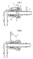
- Fig. 7
- ein Steckverbindungsgehäuse mit montiertem Anzeigeteil beim Einführen eines Einsteckteils vor dem Einrasten der Halterippe und
- Fig. 8
- die gleiche Montagesituation nach dem Einrasten der Halterippe mit Anzeige der korrekten Montage.
- Fig. 1
- a connector housing with mounted display part in section along line II in Fig. 2,
- Fig. 2
- 2 shows a cross section through the housing according to line II-II in FIG. 1 with the display part engaged,
- Fig. 3
- the display part according to the invention in the untensioned state,
- Fig. 4
- a partial view of the display part of FIG. 3 in the tensioned state in the mounting position above the opening of the plug housing before snapping
- Fig. 5
- a holding element in plan view in the assembly position before insertion into the recess in the housing wall,
- Fig. 6
- the same holding element in side view,
- Fig. 7
- a connector housing with a mounted display part when inserting a plug-in part before snapping the retaining rib and
- Fig. 8
- the same assembly situation after the retaining ribs have snapped in, indicating that the assembly is correct.
Die in den Figuren dargestellte Steckverbindung dient zur lösbaren Verbindung von
Rohrleitungen und insbesondere von Kraftstoffleitungen im Kraftfahrzeugbau. Die
Steckverbindung besteht hierbei aus einem zylindrischen Steckgehäuse 1, einem
rohrförmigen Einsteckteil 2 mit einer umlaufenden Halterippe 3 sowie einem mit dem
Steckgehäuse 1 verbindbaren Anzeigeteil 4. The plug connection shown in the figures is used for the detachable connection of pipelines and in particular of fuel lines in motor vehicle construction. The plug-in connection here consists of a cylindrical plug-in housing 1, a tubular plug-in
Das Steckgehäuse 1 weist in seinem Einsteckbereich einen Aufnahmeraum 5 für ein
separates Halteelement 6 auf, welches von außen quer zur Gehäuseachse durch
eine entsprechende Aussparung 7 in der Gehäusewand 8 in Richtung des Pfeiles Z
eingeführt wird. Dieses Halteelement 6 besitzt, wie aus Figur 5 und 6 ersichtlich,
Stützkörper 9 mit radial nach innen gerichteten Rastkanten 10, die dazu bestimmt
sind, die Halterippe 3 nach dem Eindrücken des Einsteckteils 2 in das Steckgehäuse
1 zu hintergreifen und in Schließposition zu halten ( Figur 8 ).The plug-in housing 1 has in its plug-in area a receiving space 5 for a
Die Stützkörper 9 sind hierbei nach der einen Seite über V-förmig
zusammengeführte Federstege 11 und eine abgerundete Verbindungsstelle 14
untereinander verbunden und nach der anderen Seite über ebenfalls V-förmig
zusammengeführte Federstege 12 mit einer Druckplatte 13 verbunden.The
Im eingebauten Zustand des Halteelements 6 sind die beiden Federstege 11 mit
ihrer abgerundeten Verbindungsstelle 14 an der Innenseite der Gehäusewand 8 in
einer entsprechenden Mulde abgestützt, während die Druckplatte 13 aus der
Gehäusewand 8 etwas übersteht. Zum Lösen der Steckverbindung drückt man die
Druckplatte 13 in die Gehäusewand 8 hinein. Dadurch werden die Stützkörper 9 mit
ihren Rastkanten 10 mittels der Federstege 11 und 12 nach außen bewegt und
geben die Halterippe 3 frei, so daß das Einsteckteil 2 sich mühelos herausziehen
läßt. Dieser Schließ- und Lösemechanismus ist im einzelnen in der EP 0 605 801 C1
beschrieben. In the installed state of the
Das in den Figuren 1, 3 und 4 dargestellte Anzeigeteil 4 besteht aus zwei V-förmig
zusammengeführten, federnd zusammendrückbaren Stegen 15, welche an der
Unterseite eines dachförmig ausgebildeten Stützlappens 17 angeformt und an ihren
freien Enden durch einen Quersteg 16 verbunden sind. Der Stützlappen 17 ist mittig
mit einer Lasche 18 verbunden, an deren Ende eine Klemmschelle 19 angeformt ist.
Diese Klemmschelle 19 ist im Innendurchmesser und in der Breite so ausgelegt, daß
sie in eine entsprechende umlaufende Nut 20 in der Gehäusewand 8 einsteckbar
und dort verankerbar ist.The
Das Anzeigeteil 4 wird an der Gehäusewand 8 so verankert , daß die Lasche 18 mit
dem Stützlappen 17 im entspannten Zustand radial nach außen absteht und nach
dem Einschwenken des Anzeigeteils 4 in Richtung des Pfeiles E durch die
aufgebrachte Biegespannung eine radial nach außen gerichtete Zugkraft P ausübt.
Die Stege 15 besitzen zu diesem Zweck, wie aus Fig. 2 und 4 ersichtlich, nach
außen abstehende Vorsprünge 21, welche im eingedrückten Zustand des
Anzeigeteils 6 in der Öffnung 22 der Gehäusewand 8 verrastbar sind.The
Diese Öffnung 22 befindet sich in Einsteckrichtung des Einsteckteils 2 hinter den
Rastkanten 10 des Halteelements 6 und hat, wie in Fig. 2 im unteren Bereich der
Gehäusewand 8 bei der gleichen Öffnung 22 deutlich erkennbar ist, eine Breite B,
welche dem äußeren Abstand A der beiden Federstege 15 dicht unterhalb des
Stützlappens 17 entspricht.This
Die Stützkörper 9 des Halteelements 6 besitzen an der gleichen Stelle unterhalb der
Öffnung 22 eine Aussparung 25 entsprechend der Breite und Dicke der Federstege
15, so daß diese in Einsteckrichtung hinter den Stützkörpern 9 bis in den
Aufnahmebereich der Halterippe 3 einführbar ist.The
Die Federstege 15 laufen von der Unterseite des Stützlappens 17 in einer Länge
entsprechend der Wanddicke der Gehäusewand 8 zunächst etwa parallel zueinander
und erweitern sich daran anschließend bis zu den Vorsprüngen 21 konisch , um
dann V-förmig bis zum Quersteg 16 wieder zusammenzulaufen. Dieser Quersteg 16
ist entsprechend der radialen Erstreckung der Halterippe 3 in Einsteckrichtung des
Einsteckteils 2 durch eine Fläche 24 abgeschrägt, wobei die Höhe h der konischen
Erweiterung bis zum Vorsprung 21 der radialen Erstreckung b der Schrägfläche 24
entspricht.The
Wenn nun das Einsteckteil 2, wie aus Figur 7 ersichtlich, in das Steckverbindungsgehäuse
1 in Richtung des Pfeiles M eingedrückt wird, werden zunächst die
Rastkanten 10 des Halteteils 6 von der Halterippe 3 auseinandergedrückt. Beim
weiteren Eindringen des Einsteckteils 2 stößt die Halterippe 3 dann gegen die
Schrägfläche 24 des Querstegs 16 und schiebt diesen durch die radial wirkende
Kraftkomponente mitsamt dem Anzeigeteil 4 nach außen. Die Federstege 15 werden
dabei durch die Öffnung 22 elastisch zusammengedrückt, bis die Vorsprünge 21 den
inneren Öffnungsrand 23 passiert haben. Sodann werden der Stützlappen 17 mit
den Federstegen 15 aufgrund der durch die vorgespannten Laschen 18
freiwerdenden Zugkraft P nach außen gezogen. Der Stützlappen 17 erhebt sich
hierbei wie eine Flagge sichtbar über das Steckverbindungsgehäuse 1 und zeigt
damit an, daß das Einsteckteil 2 korrekt montiert ist ( Figur 8). If , as can be seen from FIG. 7 , the plug-in
Claims (5)
- A releasable plug connection with assembly indication for connecting lines for fluid and gaseous substances, comprising a tubular plug-in member (2) which has a holding rib (3) extending therearound and which can be connected to the end of the one pipeline, a cylindrical plug housing (1) which can be connected to the end of the other pipeline and which has a receiving space (5) for a separate holding element (6) with radially inwardly directed latching edges (7) which can be elastically sprung open for engaging behind the holding rib (3) after the plug-in member (2) has been pressed in, and an indicator member (4) which projects radially into the receiving space (5) into the receiving region of the holding rib (3) behind the latching edges (10) of the holding element (6) in the insertion direction and which is bevelled in the insertion direction corresponding to the radial extent of the holding rib (3) in such a way that after complete penetration of the holding rib (3) the indicator member (4) is displaced thereby, characterised in that the indicator member (4) comprises legs (15) which are brought together in a V-shape in the radial plane and which can be resiliently pressed together and which are connected together at the lower end by a transverse leg (16) having an inclined surface (24) and which in the pressed-in condition of the indicator member (4) can be latched press-stud-like with outwardly projecting projections (21) in an opening (22) in the housing wall (8), wherein at their ends projecting from the opening (22) the legs (15) are connected to a tongue (18) which can be sprung open and which is adapted to be anchorable at the opposite end thereof to the plug housing (1).
- A releasable plug connection according to claim 1 characterised in that formed at the free end of the tongue (18) is a clamping clip (19) which can be inserted into a corresponding peripherally extending groove (20) in the housing wall (8).
- A releasable plug connection according to claim 1 or claim 2 characterised in that the tongue (18) projects radially outwardly with the indicator member (4) in the relaxed condition and in the pressed-in condition applies a radially outwardly directed pulling force (P) to the indicator member (4).
- A releasable plug connection according to one of claims 1 to 3 characterised in that the indicator member (4) is supported on both sides of the opening (22) with lugs (17) which bear resiliently against the housing wall (8).
- A releasable plug connection according to one of claims 1 to 4 characterised in that the spring legs (15) initially extend parallel from the lug (17) correspondingly to the width (B) of the opening (22) and the thickness of the housing wall (8) and in the inwardly adjoining region conically diverge as far as the projections (21), wherein the height (h) of the conical enlargement as far as the projection (21) is equal to the radial extent (b) of the inclined surface (21) at the lower transverse leg (16) of the spring legs (15).
Applications Claiming Priority (2)
| Application Number | Priority Date | Filing Date | Title |
|---|---|---|---|
| DE19708377A DE19708377C1 (en) | 1997-03-01 | 1997-03-01 | Detachable plug-in connector for gas and liquid pipes |
| DE19708377 | 1997-03-01 |
Publications (2)
| Publication Number | Publication Date |
|---|---|
| EP0862009A1 EP0862009A1 (en) | 1998-09-02 |
| EP0862009B1 true EP0862009B1 (en) | 2001-09-26 |
Family
ID=7821952
Family Applications (1)
| Application Number | Title | Priority Date | Filing Date |
|---|---|---|---|
| EP98102351A Expired - Lifetime EP0862009B1 (en) | 1997-03-01 | 1998-02-11 | Releasable plug in coupling |
Country Status (6)
| Country | Link |
|---|---|
| US (1) | US6082779A (en) |
| EP (1) | EP0862009B1 (en) |
| JP (1) | JP4065570B2 (en) |
| DE (1) | DE19708377C1 (en) |
| ES (1) | ES2165106T3 (en) |
| WO (1) | WO1998038450A1 (en) |
Families Citing this family (44)
| Publication number | Priority date | Publication date | Assignee | Title |
|---|---|---|---|---|
| DE19722842C2 (en) * | 1997-05-30 | 2001-04-12 | Raymond A & Cie | Detachable quick coupling |
| DE19923636A1 (en) * | 1999-05-22 | 2000-11-23 | Murrplastik Systemtechnik Gmbh | Threaded connector for protective hoses end part with annular internal shoulder near foot of springs, tubular ring seal can be introduced between shoulder and free ends of springs |
| KR100331471B1 (en) * | 1999-11-16 | 2002-04-09 | 황현식 | Connector of a fuel pipe for vehicle |
| GB0011317D0 (en) * | 2000-05-10 | 2000-06-28 | John Guest International Limit | Tube couplings |
| DE10025817C2 (en) * | 2000-05-24 | 2002-06-20 | Raymond A & Cie | Detachable quick coupling with safety catch |
| DE50004661D1 (en) * | 2000-09-20 | 2004-01-15 | Ti Automotive Fuldabrueck Gmbh | Coupling, in particular quick coupling, for fuel pipe sections |
| US6688654B2 (en) * | 2000-12-08 | 2004-02-10 | Newfrey Llc | One piece quick connector |
| FR2818731B1 (en) * | 2000-12-22 | 2006-11-03 | Legris Sa | FAST COUPLER WITH CONNECTION LAMP |
| DE10115399C1 (en) * | 2001-03-29 | 2002-06-06 | Raymond A & Cie | Detachable push-fit coupling, for fluid pipes, has insert part and housing and with additional locking element displaced crosswise between opening and closing position |
| DE10126205C1 (en) * | 2001-05-30 | 2002-04-04 | Raymond A & Cie | Releasable plug-in coupling, for fluid line e.g. automobile fuel line, has sliding protection sleeve for preventing accidental operation of release pressure plates |
| FR2829829B1 (en) * | 2001-09-20 | 2004-02-13 | Legris Sa | SECURE MOUNTING CONNECTION DEVICE |
| JP3988180B2 (en) * | 2002-02-28 | 2007-10-10 | 東海ゴム工業株式会社 | Quick connector with connection confirmation function |
| DE10219442B4 (en) * | 2002-05-02 | 2010-09-16 | Mann + Hummel Gmbh | connector |
| US7316428B2 (en) * | 2002-10-07 | 2008-01-08 | Tokai Rubber Industries, Ltd. | Connection verifying device and connection verifying structure for a pipe and a connector |
| FR2847647B1 (en) * | 2002-11-25 | 2007-10-05 | SAFETY CONNECTION INCREASED | |
| US6810569B1 (en) | 2003-07-08 | 2004-11-02 | Visteon Global Technologies, Inc. | Workpiece release with computer verified connections |
| US7390025B2 (en) * | 2004-03-31 | 2008-06-24 | Ti Group Automotive Systems, Llc | Secondary latch/verifier for a quick connector |
| US20050236833A1 (en) * | 2004-04-23 | 2005-10-27 | Poirier David M | Tube lock quick connector |
| DE102004052475A1 (en) * | 2004-10-28 | 2006-05-04 | Eaton Fluid Power Gmbh | Pull-resistant plug-in coupling |
| DE102004062207B3 (en) * | 2004-12-23 | 2005-10-20 | Kirchner Fraenk Rohr | Connecting device for connecting up pipelines has locking element with first spring arm carrying holding sector |
| GB2428278B (en) * | 2005-07-09 | 2010-03-17 | Ford Global Tech Llc | A fluid connector assembly |
| FR2891344B1 (en) * | 2005-09-29 | 2009-04-10 | Hutchinson Sa | CONNECTABLE CONNECTION BETWEEN A FLUID CONDUIT AND A RIGID TUBULAR BIT. |
| FR2891889B1 (en) * | 2005-10-07 | 2009-03-06 | Caillau Ets | SEALED CONNECTION TIP AND TERMINAL PIECE FOR SUCH A TIP |
| DE102005055549B4 (en) * | 2005-11-18 | 2010-05-12 | A. Raymond & Cie | clutch |
| DE102005056777B3 (en) * | 2005-11-28 | 2006-11-30 | Rasmussen Gmbh | Insertion coupling to connect two fluid lines has assembly indicator with two arms locked to one of webs while ring is not locked behind stop surface |
| US7497480B2 (en) * | 2006-04-07 | 2009-03-03 | Ti Group Automotive Systems, Llc | Hybrid quick connector |
| DE102006017816B4 (en) * | 2006-04-13 | 2008-04-24 | Eaton Fluid Power Gmbh | Inner chiller heat exchanger |
| DE102006047267B4 (en) | 2006-10-04 | 2010-02-04 | A. Raymond Et Cie | Coupling part for a fluid line coupling |
| US7699356B2 (en) * | 2007-05-10 | 2010-04-20 | Craig Assgembly, Inc. | Quick connector for fluid conduit |
| FR2919372B1 (en) * | 2007-07-25 | 2013-05-10 | Legris Sa | LIGHTING CONNECTION. |
| KR102025623B1 (en) * | 2010-05-04 | 2019-09-26 | 노마 유.에스. 홀딩 엘엘씨 | Quick connector assembly |
| DE102010048107A1 (en) * | 2010-10-09 | 2012-04-12 | Norma Germany Gmbh | Connecting element for a fluid connection |
| CN103703296B (en) | 2011-06-02 | 2017-07-28 | A·雷蒙德公司 | The connector manufactured by three dimensional printing |
| US8967209B2 (en) * | 2012-03-29 | 2015-03-03 | Superior Power Tool Co., Ltd. | Adapter structure for a gas fuel bottle |
| WO2015069638A1 (en) | 2013-11-06 | 2015-05-14 | Becton Dickinson and Company Limited | System for closed transfer of fluids with a locking member |
| US9528644B2 (en) * | 2013-12-12 | 2016-12-27 | Zoje Kitchen & Bath Co. Ltd. | Quick connector assembly |
| DE102015109581A1 (en) | 2015-06-16 | 2016-12-22 | Johannes Schäfer vorm. Stettiner Schraubenwerke GmbH & Co. KG | Plug connection for pipelines with connection indicator |
| JP6509149B2 (en) * | 2016-03-02 | 2019-05-08 | 株式会社ニフコ | Locking mechanism of tubular body |
| DE102017001396A1 (en) * | 2017-02-14 | 2018-08-16 | Kottmann Technology Gmbh | Quick connection device, quick connection system and manufacturing method |
| WO2018216143A1 (en) * | 2017-05-24 | 2018-11-29 | 株式会社ニフコ | Lock mechanism for tubular body |
| US11199281B2 (en) | 2018-01-31 | 2021-12-14 | A. Raymond Et Cie. | Dual-latch quick connector |
| DE102018219440A1 (en) * | 2018-11-14 | 2020-05-14 | Fränkische Industrial Pipes GmbH & Co. KG | Connecting unit |
| KR102520517B1 (en) * | 2021-06-10 | 2023-04-17 | 부국산업주식회사 | Monitoring Window type Quick Connector |
| WO2023019013A1 (en) * | 2021-08-13 | 2023-02-16 | Dlhbowles, Inc. | Vda connector assembly with verification |
Family Cites Families (8)
| Publication number | Priority date | Publication date | Assignee | Title |
|---|---|---|---|---|
| US4753458A (en) * | 1986-08-28 | 1988-06-28 | Harvard Industries, Inc. | Quick connector assembly |
| JP2691550B2 (en) * | 1988-03-01 | 1997-12-17 | 臼井国際産業株式会社 | Connector for small-diameter piping connection |
| JPH0538318Y2 (en) * | 1988-03-08 | 1993-09-28 | ||
| FR2636714B1 (en) * | 1988-09-21 | 1991-01-25 | Hutchinson | QUICK CONNECTION DEVICE, PARTICULARLY FOR FLUID CONDUITS IN A MOTOR VEHICLE |
| US5152555A (en) * | 1991-03-26 | 1992-10-06 | Itt Corporation | Quick connect insertion indicator clip |
| DE4300037C1 (en) | 1993-01-02 | 1994-04-21 | Raymond A & Cie | Releasable socket coupling device for pipe - has formed retaining edges onto rib with deformable guides for plug insertion |
| US5395140A (en) * | 1993-05-13 | 1995-03-07 | Enhanced Applications, L.C. | Secondary latch and indicator for fluid coupling |
| FR2705431B1 (en) * | 1993-05-14 | 1995-07-13 | Legris Sa | Quick connector with indicating device. |
-
1997
- 1997-03-01 DE DE19708377A patent/DE19708377C1/en not_active Expired - Fee Related
-
1998
- 1998-02-11 ES ES98102351T patent/ES2165106T3/en not_active Expired - Lifetime
- 1998-02-11 EP EP98102351A patent/EP0862009B1/en not_active Expired - Lifetime
- 1998-02-12 WO PCT/EP1998/000795 patent/WO1998038450A1/en active Search and Examination
- 1998-02-12 JP JP53723798A patent/JP4065570B2/en not_active Expired - Fee Related
- 1998-02-27 US US09/032,573 patent/US6082779A/en not_active Expired - Fee Related
Also Published As
| Publication number | Publication date |
|---|---|
| DE19708377C1 (en) | 1998-06-18 |
| ES2165106T3 (en) | 2002-03-01 |
| JP4065570B2 (en) | 2008-03-26 |
| EP0862009A1 (en) | 1998-09-02 |
| WO1998038450A1 (en) | 1998-09-03 |
| US6082779A (en) | 2000-07-04 |
| JP2001513174A (en) | 2001-08-28 |
Similar Documents
| Publication | Publication Date | Title |
|---|---|---|
| EP0862009B1 (en) | Releasable plug in coupling | |
| EP0965014B1 (en) | Joining and connecting element for corrugated pipes | |
| DE102006019257B4 (en) | Fluid line coupling | |
| EP1845299B1 (en) | Connecting device for a pipe | |
| EP0906534B1 (en) | Releasable plug connector with fitting indicator | |
| DE10250421A1 (en) | connecting element | |
| EP1969280B1 (en) | Plug-in part for a plug connector arrangement | |
| CH667139A5 (en) | CONNECTING FITTING. | |
| WO2006018384A1 (en) | Plug connection for fluid lines | |
| EP1318343A2 (en) | Connector | |
| DE102014103535A1 (en) | Device for fastening a component to a carrier component | |
| EP1557600B1 (en) | Socket joint for connecting a fluid line with a pipe | |
| EP2198170B1 (en) | Device for fixing an attachment to a supporting part | |
| DE10025817C2 (en) | Detachable quick coupling with safety catch | |
| DE3346423A1 (en) | Pipe clamp | |
| DE10322124A1 (en) | Device for determining at least one parameter of a medium flowing in a line | |
| DE3705610A1 (en) | DETACHABLE CONNECTOR FOR PIPELINES | |
| EP2035737B1 (en) | Collar for joining two pipes comprising one respective connecting neck | |
| DE4217646C1 (en) | Push in connector for two pipe sections - has coaxially interfitting connectors with spring clip locked even in release position on one part by locking element with detent allowing pre-fitting | |
| DE102009037304A1 (en) | Automotive air conditioning system | |
| EP3361135A1 (en) | Quick connecting device and quick connecting system | |
| EP3153757B1 (en) | Detachable plug connection for pipes | |
| DE3901104C2 (en) | Connector with locking function for fluid-carrying lines | |
| DE19848489B4 (en) | Detachable plug connection for the connection of pipelines | |
| DE19932744C2 (en) | Spring element for the detachable connection of a fork head to a bearing journal |
Legal Events
| Date | Code | Title | Description |
|---|---|---|---|
| PUAI | Public reference made under article 153(3) epc to a published international application that has entered the european phase |
Free format text: ORIGINAL CODE: 0009012 |
|
| AK | Designated contracting states |
Kind code of ref document: A1 Designated state(s): ES FR GB IT |
|
| AX | Request for extension of the european patent |
Free format text: AL;LT;LV;MK;RO;SI |
|
| 17P | Request for examination filed |
Effective date: 19990302 |
|
| AKX | Designation fees paid |
Free format text: ES FR GB IT |
|
| RBV | Designated contracting states (corrected) |
Designated state(s): ES FR GB IT |
|
| REG | Reference to a national code |
Ref country code: DE Ref legal event code: 8566 |
|
| GRAG | Despatch of communication of intention to grant |
Free format text: ORIGINAL CODE: EPIDOS AGRA |
|
| GRAG | Despatch of communication of intention to grant |
Free format text: ORIGINAL CODE: EPIDOS AGRA |
|
| GRAH | Despatch of communication of intention to grant a patent |
Free format text: ORIGINAL CODE: EPIDOS IGRA |
|
| 17Q | First examination report despatched |
Effective date: 20010223 |
|
| GRAH | Despatch of communication of intention to grant a patent |
Free format text: ORIGINAL CODE: EPIDOS IGRA |
|
| GRAA | (expected) grant |
Free format text: ORIGINAL CODE: 0009210 |
|
| AK | Designated contracting states |
Kind code of ref document: B1 Designated state(s): ES FR GB IT |
|
| ET | Fr: translation filed | ||
| REG | Reference to a national code |
Ref country code: GB Ref legal event code: IF02 |
|
| GBT | Gb: translation of ep patent filed (gb section 77(6)(a)/1977) |
Effective date: 20011201 |
|
| REG | Reference to a national code |
Ref country code: ES Ref legal event code: FG2A Ref document number: 2165106 Country of ref document: ES Kind code of ref document: T3 |
|
| PLBE | No opposition filed within time limit |
Free format text: ORIGINAL CODE: 0009261 |
|
| STAA | Information on the status of an ep patent application or granted ep patent |
Free format text: STATUS: NO OPPOSITION FILED WITHIN TIME LIMIT |
|
| 26N | No opposition filed | ||
| PGFP | Annual fee paid to national office [announced via postgrant information from national office to epo] |
Ref country code: ES Payment date: 20030127 Year of fee payment: 6 |
|
| PGFP | Annual fee paid to national office [announced via postgrant information from national office to epo] |
Ref country code: GB Payment date: 20030210 Year of fee payment: 6 |
|
| PGFP | Annual fee paid to national office [announced via postgrant information from national office to epo] |
Ref country code: FR Payment date: 20040210 Year of fee payment: 7 |
|
| PG25 | Lapsed in a contracting state [announced via postgrant information from national office to epo] |
Ref country code: GB Free format text: LAPSE BECAUSE OF NON-PAYMENT OF DUE FEES Effective date: 20040211 |
|
| PG25 | Lapsed in a contracting state [announced via postgrant information from national office to epo] |
Ref country code: ES Free format text: LAPSE BECAUSE OF NON-PAYMENT OF DUE FEES Effective date: 20040212 |
|
| GBPC | Gb: european patent ceased through non-payment of renewal fee |
Effective date: 20040211 |
|
| PG25 | Lapsed in a contracting state [announced via postgrant information from national office to epo] |
Ref country code: IT Free format text: LAPSE BECAUSE OF NON-PAYMENT OF DUE FEES Effective date: 20050211 |
|
| REG | Reference to a national code |
Ref country code: ES Ref legal event code: FD2A Effective date: 20040212 |
|
| PG25 | Lapsed in a contracting state [announced via postgrant information from national office to epo] |
Ref country code: FR Free format text: LAPSE BECAUSE OF NON-PAYMENT OF DUE FEES Effective date: 20051031 |
|
| REG | Reference to a national code |
Ref country code: FR Ref legal event code: ST Effective date: 20051031 |