EP0861397B1 - Multiple-tube flexible pipe having high compressive strength - Google Patents
Multiple-tube flexible pipe having high compressive strength Download PDFInfo
- Publication number
- EP0861397B1 EP0861397B1 EP96939963A EP96939963A EP0861397B1 EP 0861397 B1 EP0861397 B1 EP 0861397B1 EP 96939963 A EP96939963 A EP 96939963A EP 96939963 A EP96939963 A EP 96939963A EP 0861397 B1 EP0861397 B1 EP 0861397B1
- Authority
- EP
- European Patent Office
- Prior art keywords
- flexible
- pipeline according
- pipe
- compressive
- central
- Prior art date
- Legal status (The legal status is an assumption and is not a legal conclusion. Google has not performed a legal analysis and makes no representation as to the accuracy of the status listed.)
- Expired - Lifetime
Links
Images


Classifications
-
- F—MECHANICAL ENGINEERING; LIGHTING; HEATING; WEAPONS; BLASTING
- F16—ENGINEERING ELEMENTS AND UNITS; GENERAL MEASURES FOR PRODUCING AND MAINTAINING EFFECTIVE FUNCTIONING OF MACHINES OR INSTALLATIONS; THERMAL INSULATION IN GENERAL
- F16L—PIPES; JOINTS OR FITTINGS FOR PIPES; SUPPORTS FOR PIPES, CABLES OR PROTECTIVE TUBING; MEANS FOR THERMAL INSULATION IN GENERAL
- F16L11/00—Hoses, i.e. flexible pipes
- F16L11/22—Multi-channel hoses
Definitions
- the present invention relates to a flexible pipe intended to connect for example an underwater oil wellhead an underwater or floating petroleum development facility.
- Flexible lines used to serve as lines of production or service have high mechanical strength in particular to internal pressure, traction and crushing, and are usually laid using tensioning devices comprising tracks provided with skids which grip the pipe and move in translation on a given race to train it jointly.
- Control umbilicals have resistance to stress less crushing than flexible pipes serving as lines of production or service due to the presence of pipes sensitive to crushing and cannot be laid with track tensioning devices.
- the umbilicals are generally laid with winches, the transmission of the traction forces being ensured by minus a layer of metal armor located in the outer shell of the pipeline.
- control umbilical we therefore prefer to have the electrical cables and / or optics of a control umbilical as close as possible to the axis central.
- control umbilical includes a pipe central, we cannot exceed a certain diameter for the latter under penalty of submitting the wound electrical and / or optical cables around it to excessive stresses likely to cause their rupture.
- the external diameter of the umbilicals therefore does not exceed 200 mm.
- the current trend is to increase the number of heads of subsea wells connected to the same production facility.
- Document DE-A-1 918 575 discloses a flexible pipe to multiple pipes but which does not include a flexible crushing force transmission arranged in an annular space provided in said pipeline.
- the present invention relates to a new pipe flexible, with multiple pipes to simplify laying operations and handling, of the type comprising a flexible central element resistant to traction and crushing and a plurality of coiled peripheral lines around said central flexible element in at least one ply in a space annular between said central flexible element and an envelope, one at least said peripheral lines being a line sensitive to crushing and / or traction.
- the central flexible element is typically a tubular pipe flexible of the type used to serve as a production line and manufactured in great length by the plaintiff.
- the central flexible element comprises an assembly of several flexible tubular conduits or consists of a cable.
- the multiple-pipe pipeline comprises at least one flexible member for transmitting crushing force adjacent to said peripheral pipe sensitive to crushing and / or to traction arranged in the annular space between said central flexible element and said envelope.
- the invention makes it possible to reconcile in a single pipe with multiple lines on the one hand a production and / or service line and / or a cable and on the other hand a control umbilical.
- This pipe can be done by means of a laying device of the type usually used for laying pipes flexible with high mechanical resistance such as those serving as lines of production or service, in particular a tracked tensioning device.
- the multi-pipe pipeline further comprises means sliding capable of allowing axial movement relative of said pipe sensitive to traction and / or crushing and the adjacent flexible crushing force transmission member.
- driving here also generally refers a liquid or gas line than an electrical cable or optical.
- said means of slip include a clearance between said at least one pipe device sensitive to crushing and / or traction and said flexible member for adjacent crushing force transmission.
- the pipe verifies the relation 2E ⁇ c ⁇ 0.6E and preferably the relation 1.6 E ⁇ c ⁇ 0.8E, where c denotes the width of said crushing force transmission member, measured at mid-thickness of said annular space and E denotes the thickness of said annular space.
- the pipe includes at least two adjacent peripheral lines sensitive to crushing and / or traction and it includes a crushing force transmission between said two pipes adjacent devices whose width c satisfies the relation c ⁇ 0.6E, preferably the relation c ⁇ 0.8E, where
- E denotes the thickness of said annular space, the width c being measured at mid-thickness of the annular space.
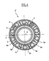
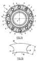
- This flexible pipe 1 comprises a flexible element central constituted by a tubular central pipe 2, resistant to the traction and the crushing, being used in the example described of line production, an envelope 8 constituted by a sheath thermoplastic and a plurality of peripheral lines 3, of 4 electric cables and force transmission components of crushing 5 arranged in a sheet in the annular space included between the casing 8 and the central pipe 2.
- the central pipe 2 can serve as a line service, and be divided into several smaller pipes including the assembly constitutes a central core resistant to traction and the crash.
- the central pipe 2 is of the type known per se for the transport of hydrocarbons and / or gases and has one or more crush-resistant layers, one or more several internal polymer sealing layers presenting the case if necessary thermal insulation properties, one or more layers generally metallic armor wire wound helically under form of crossed plies ensuring tensile strength and protective outer polymer layer. Conducts of this type are manufactured in great length by the applicant company. Their external diameter is typically greater than 100 mm.
- the central pipe 2 and the envelope 8 are concentric and each have a section transverse circular.
- peripheral lines 3 and electrical cables 4 are angularly distributed around the central axis X of line 1 and have the same external diameter.
- peripheral lines 3 eight in number in the example described, are hydraulic lines sensitive to crushing, and to a lesser extent sensitive to traction.
- the radial dimension or thickness E of the annular space preferably checks the relationships: d ⁇ E ⁇ 3d, advantageously d ⁇ E ⁇ 1.5d.
- the pipes devices are wound in the example described in a helix around the central pipe 2 with a constant helix angle between 10 ° and 30 °, preferably equal to 15 °.
- Flexible force transmission members 5 are each arranged as shown in the figures between two peripheral lines 3 or between an electric cable 4 and the adjacent peripheral pipe 3.
- the organs crushing force transmission hoses 5 are formed each by a profile made by extrusion in a plastic material shore D hardness greater than or equal to 30, and advantageously greater than or equal to 50.
- each flexible member 5 substantially follows, by its faces radially internal and radially external, cylindrical of revolution around the central axis x, the shape of the outer surface of the central pipe 2 and the shape of the inner surface of envelope 8 respectively.
- Each flexible member 5 also marries substantially by its lateral faces the cylindrical shapes of revolution of the adjacent peripheral lines 3 or 4.
- Flexible force transmission devices 5 can be made of high or low polyethylene density, polyamide, polypropylene, PVC, polyurethane, possibly reinforced by a load of fibers such as fiberglass, or a syntactic foam.
- the flexible force transmission members of crushing 5 are provided on their lateral flanks with notches 10, advantageously arranged in staggered rows, and intended to increase the flexural deformability.
- Central pipe 2 thus takes up most of the tensile forces to which the pipe 1 is subjected.
- the central pipe takes up at least 75% tensile forces exerted on line 1, or even at least 80 or 90% of said efforts.
- the envelope 8 can thus advantageously be constituted by a sheath not having a tensile strength particular, for example a sheath made of a polymer such as low density polyethylene or polyamide.
- the bodies for transmitting crushing forces 5 are hollowed out internally for the sake of saving material and have internal cavities 9 of circular cross section.
- the flexible member 5 does not include preferably no internal cavity 9.
- the distance m between two peripheral pipes is advantageously greater than or equal to 0.7 times the thickness E.
- the spacing m is substantially equal to E.
- each flexible member 5 measured at mid-thickness of the annular space E, verify the relationship: 1.5 ⁇ c / E ⁇ 0.6.
- the distance from the internal cavities 9 to a adjacent peripheral line 3 or 4 is greater than 0.3 times and preferably 0.5 times the thickness E and the radial dimension h of the internal cavities 9 is preferably less than 0.8 times the thickness E.
- each flexible member for transmitting crushing force 5 consists of a profile wound in a continuous helix around the central pipe 2 and has lateral section faces transverse in the shape of an arc of a circle, shaped to match substantially the shape of the external surface of the pipes adjacent peripherals, leaving an annular clearance j with these past.
- the flexible transmission members of crushing force 5 can be extruded in a single block of material around peripheral pipes susceptible to crushing and / or tensile, the latter having been previously coated a lubricant to allow axial sliding between the members crushing force transmission hoses 5 and said peripheral pipes when the pipe is flexed, as will be explained below.
- the ring clearance j gives to the peripheral conduits susceptible to traction and / or crushing a possibility of axial sliding relative to the flexible transmission members 5 adjacent crushing force and thus constitutes a means of slip to avoid the appearance, when line 1 is flexed, caused by excessive tensile stresses by friction effects between the peripheral pipes and the crushing force transmission members 5 in the portions of the peripheral lines in the region of the pipeline located on the radially outer side with respect to the concavity of the line 1 curved, thus avoiding damage to the pipes peripherals sensitive to traction and / or crushing.
- the clearance j between a peripheral pipe sensitive to traction and / or crushing, of external diameter d, and the adjacent force transmission member 5 checks the relationship 0.6 ⁇ d / d ⁇ 0.03 advantageously 0.3 ⁇ d / d ⁇ 0.05
- the envelope 8 is produced in the embodiment example described by extruding a plastic material.
- the envelope 8 could be produced by means a ribbon of heat-shrinkable plastic wrapped around peripheral lines and flexible transmission components of crushing effort or by means of an adhesive tape, taking care however, do not interfere with the relative sliding of the pipes devices sensitive to traction and / or crushing and flexible crushing force transmission members.
- the external radius r of the central element 2 is, in the embodiment described with reference to FIGS. 1 to 3, greater than 50 mm, and can reach or exceed 100 mm.
- the external radius R of line 1 can reach up to three times the radius r of the central flexible element 2.
- FIGS 4 and 5 show a pipe flexible 1 ′ with multiple pipes conforming to a second example of realization of the invention.
- two adjacent peripheral pipes 3 are separated by two flexible crushing force transmission members 5 a, each providing, with the adjacent peripheral pipe, a clearance j as described above, and moreover providing between them a game w.
- peripheral pipes and the flexible crushing force transmission members 5 a which are formed by profiles, are wound around the central pipe 2 according to helical segments. with inversion of the "SZ" type helix angle.
- the winding of the "S-Z" type comprises a succession of identical winding patterns repeating periodically and each comprising, on the one hand, segments wound in a helix with a constant helix angle in a positive direction (A1, B1; A'1, B'1) and helically wound segments with a constant helix angle in the negative direction (B2, A2; B'2, A'2 not shown) and, on the other hand, winding direction reversal segments ensuring variation progressive winding angle between said angle segments constant helix (B1, B2; B'1, B'2).
- Figures 6 and 7 correspond to a winding in which we do a little less than one turn in one direction then in the other. More precisely, between the reversal points of winding, of axial positions x1 and x2, we wind in one direction on an angular travel equal to 320 °, then between the positions axial x2, x3, we wind in the opposite direction on the same stroke angular.
- Figures 8 and 9 correspond to a winding in which is wound each peripheral pipe or flexible member 5 a full turn plus 320 ° in a winding direction between the direction reversal points of axial positions x'1 and x'2 then we winds a full turn plus 320 ° in the opposite direction between the points of axial positions x'2 and x'3 (not illustrated in the figures).
- FIG. 6 A full cyclic pattern is shown in Figures 6 and 7 between the axial positions x1 and x3.
- Figures 8 and 9 we only represented the first half of a cyclic pattern between the axial positions x'1 and x'2.
- the "S-Z" type winding is advantageous because the machines to realize it are simpler than those used for helical winding at constant pitch.
- the lateral clearance is not constant, being maximum (jmax) at the winding direction change points (which correspond to the axial positions x2 and x'2 on the examples of Figures 6 to 9) and passing through minima (jmin) between these points.
- the winding is in sections of "S-Z" type propellers.
- the angle helix of the helical segments is preferably alternately equal at + 15 ° and -15 °.
- the angular path of each propeller section between two winding direction reversal points is worth preferably (Nx360 °) -40 ° +/- 30 ° and advantageously (Nx360 °) -40 ° +/- 15 °, N being an integer equal to or greater than 1.
- This configuration has the advantage of globally balancing the constraints of traction applied to the peripheral pipes of the pipeline when it is flexed.
- the peripheral lines can be wound in a helix (constant helix angle) in the annular space between the central pipe and casing.
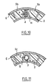
- a peripheral line such as a 4-wire cable example has an external diameter d smaller than the dimension radial E of the annular space between the central pipe 2 and the inner surface of the casing 8, preferably as shown in Figures 10 the cable 4 (or alternatively a pipe 3) in a groove 11 opening onto the central pipe 2.
- the groove 11 is formed between two crushing force transmission members 5 b providing a lateral clearance v between them and a radial clearance p with the cable 4 (or alternatively conduct 3).
- the clearance v is less than half the clearance p.
- this peripheral pipe 3 (or alternatively this cable 4) is advantageously, as shown in FIG. 11, arranged in a groove 12 formed in a flexible member for transmitting crushing force 5 c opening onto the central pipe 2.
- the groove 12 is shaped so as to accommodate the pipe 3 (or alternatively the cable 4) with a clearance q.
- FIG. 12 a flexible pipeline 1 "having peripheral pipes 3 was compression-sensitive, similar to the devices 3 of the previous embodiments pipes, and pipes 3b relatively rigid, for example the same type as the central pipe 2 or possibly metal tubes or cables.
- the pipes 3 b can ensure the transmission of the crushing forces, it is not necessary for the region of the annular space comprised between a peripheral pipe 3 a and a pipe 3 b adjacent close enough to be filled by a flexible member for transmitting compressive-load 5 as described above and it is sufficient to fill this space to use a filler material having a hardness not particular, for example a Shore D hardness of elastomeric material less than 30 in the case where the distance between the pipe 3 b and the driving Externa adjacent risk 3 a is less than or equal to 1.5 times the external diameter of the peripheral pipe.
- FIG. 13 shows a pipe 1 "' comprising a central pipe 2 serving as a production line, a plurality of peripheral lines 28 serving as a service line, and two control umbilicals 13 and 14 arranged in space ring between the casing and the central pipe 2.
- the pipes peripherals 28 and the umbilicals 13,14 are separated by organs crushing force transmission hoses 5 as described previously.
- the envelope comprises an internal plastic sheath 8 a , an armor formed by two crossed plies of metal wires 8 b and an external plastic sheath 8 c .
- the resistance to crushing forces of a pipe can be characterized by stiffness, assessed by measuring the mass at apply between two parallel plates enclosing a meter of conducted to lead to a radial deformation equal to 1%. In the case of the central pipe 2, this stiffness is advantageously greater than or equal to 5t / m /%.
- Crush resistance crush-sensitive lines can be characterized by stiffness less than 0.5 t / m /% and most often less than 0.2 t / m /%.
- the stiffness necessary for a pipe to support crushing forces due to laying and handling means is typically greater than 0.5 t / m /% and most often greater than 1t / m /%.
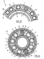
- FIG. 14 shows a pipe 1 "" in which the casing 8 consists of a single layer of polyamide 5.2mm thick PAll.
- Each flexible force transmission member 5 crushing is made of high density polyethylene “LUPOLEN” and presents in cross section the shape shown in the figure 15.
- the radially internal surface 20 of the flexible member 5 has a radius of curvature equal in the example described to 58.9 mm.
- the radial dimension E is 16.5 mm and the distance between the sides 21 is 21.5 mm.
- the distance between the lateral ends of the surface radially external 22 is 37.5 mm.
- Central pipe 2 is a conduct carried out by the applicant company, of the "COFLEXIP" type, internal diameter equal to 63.5 mm (2.5 ”) and external diameter equal to 108.9 mm, this pipe withstands an internal pressure of 6350 PSI (438 Bar).
- a pipe can be made to multiple pipes with a central pipe resistant to crushing and traction, of large external diameter, and electrical and / or optical cables wrapped around this pipe without breaking them when the pipeline is bending, despite their distance from the central axis of the pipeline.
Description
La présente invention concerne une canalisation flexible destinée à relier par exemple une tête de puits de pétrole sous-marin à une installation d'exploitation pétrolière sous-marine ou flottante.The present invention relates to a flexible pipe intended to connect for example an underwater oil wellhead an underwater or floating petroleum development facility.
Une tête de puits de pétrole sous-marin est habituellement reliée à une installation d'exploitation pétrolière sous-marine ou flottante par plusieurs canalisations, dont :
- une ligne de production constituée par une conduite flexible, destinée à l'acheminement des hydrocarbures liquides,
- une ligne de service constituée par une ou plusieurs conduites flexibles, destinée à l'acheminement d'hydrocarbures gazeux de dégazage ou de gaz comprimé pour provoquer la remontée des hydrocarbures liquides,
- un ombilical de commande comportant une ou plusieurs conduites hydrauliques sensibles à l'écrasement et/ou des câbles électriques et/ou optiques pour la transmission d'énergie et/ou d'informations.
- a production line consisting of a flexible pipe, intended for the transportation of liquid hydrocarbons,
- a service line consisting of one or more flexible pipes, intended for the delivery of degassing gaseous hydrocarbons or compressed gas to cause the rise of liquid hydrocarbons,
- a control umbilical comprising one or more hydraulic lines sensitive to crushing and / or electrical and / or optical cables for the transmission of energy and / or information.
Les conduites flexibles utilisées pour servir de lignes de production ou de service présentent une résistance mécanique élevée en particulier à la pression interne, à la traction et à l'écrasement, et sont habituellement posées au moyen de dispositifs tensionneurs comportant des chenilles munies de patins qui enserrent la conduite et se déplacent en translation sur une course donnée pour l'entraíner conjointement.Flexible lines used to serve as lines of production or service have high mechanical strength in particular to internal pressure, traction and crushing, and are usually laid using tensioning devices comprising tracks provided with skids which grip the pipe and move in translation on a given race to train it jointly.
Les efforts de traction appliqués par ces dispositifs tensionneurs à chenilles sur une conduite flexible peuvent être considérables lors de la pose à grande profondeur, et les forces de compression exercées par les patins sur la conduite doivent être suffisamment élevées pour éviter tout glissement relatif entre les patins et la conduite.The tensile forces applied by these devices track tensioners on a flexible pipe can be considerable when laying at great depths, and the forces of compression applied by the pads on the pipe must be high enough to avoid relative slippage between skates and driving.
Les ombilicaux de commande ont une résistance aux efforts d'écrasement moindre que les conduites flexibles servant de lignes de production ou de service en raison de la présence de conduites sensibles à l'écrasement et ne peuvent être posés au moyen de dispositifs tensionneurs à chenilles. Control umbilicals have resistance to stress less crushing than flexible pipes serving as lines of production or service due to the presence of pipes sensitive to crushing and cannot be laid with track tensioning devices.
La pose des ombilicaux s'effectue généralement avec des treuils, la transmission des efforts de traction étant assurée par au moins une couche d'armure en métal située dans l'enveloppe externe de la canalisation.The umbilicals are generally laid with winches, the transmission of the traction forces being ensured by minus a layer of metal armor located in the outer shell of the pipeline.
Par ailleurs, les câbles électriques et/ou optiques présents dans les ombilicaux ont une mauvaise résistance à la traction.In addition, electrical and / or optical cables present in umbilicals have poor tensile strength.
Or, les contraintes de traction auxquelles peuvent être soumises les différentes couches d'un faisceau de câbles mis en flexion augmentent à mesure que l'on s'éloigne de l'axe central (ou fibre neutre).However, the tensile stresses to which can be submitted the different layers of a bundle of cables laid flexion increases as one moves away from the central axis (or neutral fiber).
On préfère donc disposer les câbles électriques et/ou optiques d'un ombilical de commande le plus près possible de l'axe central. Dans le cas où l'ombilical de commande comporte une conduite centrale, on ne peut excéder pour cette dernière un certain diamètre sous peine de soumettre les câbles électriques et/ou optiques enroulés autour de celle-ci à des contraintes excessives susceptibles d'entraíner leur rupture.We therefore prefer to have the electrical cables and / or optics of a control umbilical as close as possible to the axis central. In the case where the control umbilical includes a pipe central, we cannot exceed a certain diameter for the latter under penalty of submitting the wound electrical and / or optical cables around it to excessive stresses likely to cause their rupture.
Dans la pratique, le diamètre externe des ombilicaux n'excède donc pas 200 mm.In practice, the external diameter of the umbilicals therefore does not exceed 200 mm.
La tendance actuelle est d'augmenter le nombre de têtes de puits sous-marines reliées à une même installation de production.The current trend is to increase the number of heads of subsea wells connected to the same production facility.
La demanderesse a proposé lors de la Conférence Offshore Technology à Houston, Texas, en 1987 de simplifier les opérations de pose et de manutention des lignes de production et de service et ombilicaux de commande en les regroupant au sein de canalisations à conduites multiples plus compactes, plus faciles à manipuler et à installer.The plaintiff proposed during the Offshore Conference Technology in Houston, Texas in 1987 to simplify operations of laying and handling of production and service lines and control umbilicals by grouping them into pipelines more compact multiple lines, easier to handle and to install.
Ces canalisations à conduites multiples doivent toutefois :
- résister aux efforts de traction très élevés en cas de pose à grande profondeur,
- résister aux efforts d'écrasement engendrés au contact d'un support incurvé ou lors du passage entre les patins d'un dispositif de pose ou de manutention à chenilles,
- présenter une flexibilité suffisante pour résister aux sollicitations mécaniques de flexion et de traction combinées dues à la houle.
- withstand very high tensile forces when laying at great depth,
- resist the crushing forces generated on contact with a curved support or when passing between the pads of a tracked laying or handling device,
- have sufficient flexibility to withstand the combined mechanical flexural and tensile stresses due to swell.
Les canalisations telles que décrites dans la Conférence précitée et qui comportent des conduites périphériques sensibles à l'écrasement sont inaptes à résister au passage dans des dispositifs tensionneurs à chenilles.The pipes as described in the aforementioned conference and which contain crush-sensitive peripheral lines are unable to withstand passage through tracked tensioning devices.
Le document DE-A-1 918 575 divulgue une canalisation flexible à conduites multiples mais qui ne comprend pas un organe flexible de transmission d'effort d'écrasement disposé dans un espace annulaire ménagé dans ladite canalisation.Document DE-A-1 918 575 discloses a flexible pipe to multiple pipes but which does not include a flexible crushing force transmission arranged in an annular space provided in said pipeline.
La présente invention a pour objet une nouvelle canalisation flexible, à conduites multiples permettant de simplifier les opérations de pose et de manutention, du type comportant un élément flexible central résistant à la traction et à l'écrasement et une pluralité de conduites périphériques enroulées autour dudit élément flexible central en au moins une nappe dans un espace annulaire compris entre ledit élément flexible central et une enveloppe, l'une au moins desdites conduites périphériques étant une conduite sensible à l'écrasement et/ou à la traction.The present invention relates to a new pipe flexible, with multiple pipes to simplify laying operations and handling, of the type comprising a flexible central element resistant to traction and crushing and a plurality of coiled peripheral lines around said central flexible element in at least one ply in a space annular between said central flexible element and an envelope, one at least said peripheral lines being a line sensitive to crushing and / or traction.
L'élément flexible central est typiquement une conduite tubulaire flexible du type utilisé pour servir de ligne de production et fabriquée en grande longueur par la demanderesse.The central flexible element is typically a tubular pipe flexible of the type used to serve as a production line and manufactured in great length by the plaintiff.
En variante, l'élément flexible central comporte un assemblage de plusieurs conduites tubulaires flexibles ou est constitué par un câble.As a variant, the central flexible element comprises an assembly of several flexible tubular conduits or consists of a cable.
Selon l'invention, la canalisation à conduites multiples comporte au moins un organe flexible de transmission d'effort d'écrasement adjacent à ladite conduite périphérique sensible à l'écrasement et/ou à la traction disposé dans l'espace annulaire compris entre ledit élément flexible central et ladite enveloppe.According to the invention, the multiple-pipe pipeline comprises at least one flexible member for transmitting crushing force adjacent to said peripheral pipe sensitive to crushing and / or to traction arranged in the annular space between said central flexible element and said envelope.
L'invention permet de concilier en une seule canalisation à conduites multiples d'une part une ligne de production et/ou de service et/ou un câble et d'autre part un ombilical de commande.The invention makes it possible to reconcile in a single pipe with multiple lines on the one hand a production and / or service line and / or a cable and on the other hand a control umbilical.
La mise en place de cette canalisation peut s'effectuer au moyen d'un dispositif de pose du type habituellement utilisé pour poser les conduites flexibles à résistance mécanique élevée telles que celles servant de lignes de production ou de service, en particulier un dispositif tensionneur à chenilles.The installation of this pipe can be done by means of a laying device of the type usually used for laying pipes flexible with high mechanical resistance such as those serving as lines of production or service, in particular a tracked tensioning device.
Selon une caractéristique particulièrement avantageuse de l'invention, la canalisation à conduites multiples comporte en outre des moyens de glissement aptes à permettre un déplacement axial relatif de ladite conduite sensible à 1a traction et/ou à l'écrasement et de l'organe flexible de transmission d'effort d'écrasement adjacent.According to a particularly advantageous characteristic of the invention, the multi-pipe pipeline further comprises means sliding capable of allowing axial movement relative of said pipe sensitive to traction and / or crushing and the adjacent flexible crushing force transmission member.
Le terme "conduite" désigne ici de manière générale aussi bien une conduite de liquide ou de gaz qu'un câble électrique ou optique.The term "driving" here also generally refers a liquid or gas line than an electrical cable or optical.
Dans la pratique, ce sont les câbles électriques ou optiques qui présentent la résistance à la traction la plus faible et ceux pour lesquels le problème de la résistance à la traction est par conséquent le plus critique, une traction excessive pouvant entraíner la rupture du câble.In practice, these are the electrical cables or optics with the lowest tensile strength and those for whom the problem of tensile strength is by therefore the most critical, excessive traction can cause cable break.
Dans une réalisation de l'invention, lesdits moyens de glissement comportent un jeu ménagé entre ladite au moins une conduite périphérique sensible à l'écrasement et/ou à la traction et ledit organe flexible de transmission d'effort d'écrasement adjacent.In one embodiment of the invention, said means of slip include a clearance between said at least one pipe device sensitive to crushing and / or traction and said flexible member for adjacent crushing force transmission.
De préférence, ce jeu j vérifie la relation
Dans une réalisation de l'invention, la canalisation
vérifie la relation 2E ≥ c ≥ 0,6E et de préférence la relation 1,6 E ≥
c ≥ 0,8E,
où c désigne la largeur dudit organe de transmission
d'effort d'écrasement, mesurée à mi-épaisseur dudit espace
annulaire et E désigne l'épaisseur dudit espace annulaire.In one embodiment of the invention, the pipe verifies the relation 2E ≥ c ≥ 0.6E and preferably the relation 1.6 E ≥ c ≥ 0.8E,
where c denotes the width of said crushing force transmission member, measured at mid-thickness of said annular space and E denotes the thickness of said annular space.
Dans une réalisation de l'invention, la canalisation comprend au moins deux conduites périphériques adjacentes sensibles à l'écrasement et/ou à la traction et elle comporte un organe de transmission d'effort d'écrasement entre lesdites deux conduites périphériques adjacentes dont la largeur c vérifie la relation c ≥ 0,6E, de préférence la relation c ≥ 0,8E, oùIn one embodiment of the invention, the pipe includes at least two adjacent peripheral lines sensitive to crushing and / or traction and it includes a crushing force transmission between said two pipes adjacent devices whose width c satisfies the relation c ≥ 0.6E, preferably the relation c ≥ 0.8E, where
E désigne l'épaisseur dudit espace annulaire, la largeur c étant mesurée à mi-épaisseur de l'espace annulaire.E denotes the thickness of said annular space, the width c being measured at mid-thickness of the annular space.
D'autres caractéristiques et avantages de la présente invention apparaítront à la lecture de la description détaillée qui va suivre, d'exemples de réalisation non limitatifs de l'invention, et à l'examen du dessin annexé sur lequel :
- la figure 1 est une vue en coupe transversale, schématique, d'une canalisation flexible à conduites multiples conforme à un premier exemple de réalisation de l'invention,
- la figure 2 est une vue à échelle agrandie représentant un détail de la figure 1,
- la figure 3 est une vue en perspective, avec arrachement partiel, de la canalisation flexible représentée sur les figures 1 et 2,
- la figure 4 est une vue en coupe transversale, schématique, d'une canalisation flexible conforme à un deuxième exemple de réalisation de l'invention,
- la figure 5 est une vue en perspective, avec arrachement partiel, de la canalisation flexible représentée sur la figure 4,
- les figures 6 à 9 illustrent différentes configurations de l'enroulement en sections d'hélices de type "S-Z",
- la figure 10 est une vue partielle, en coupe transversale, représentant un détail de réalisation d'une canalisation flexible conforme à un troisième exemple de réalisation de l'invention,
- la figure 11 est une vue analogue à la figure 10 représentant un détail de réalisation d'une canalisation flexible conforme à un quatrième exemple de réalisation de l'invention,
- la figure 12 est une vue partielle, en coupe transversale, d'une canalisation flexible conforme à un cinquième exemple de réalisation de l'invention,
- la figure 13 est une vue en coupe transversale d'une canalisation flexible conforme à un sixième exemple de réalisation de l'invention,
- la figure 14 est une vue en coupe transversale d'une canalisation flexible conforme à un septième exemple de réalisation de l'invention, et
- la figure 15 est une vue en coupe transversale d'un organe de transmission d'effort d'écrasement utilisé dans la canalisation représentée sur la figure 14.
- FIG. 1 is a schematic cross-sectional view of a flexible pipe with multiple pipes in accordance with a first embodiment of the invention,
- FIG. 2 is an enlarged view showing a detail of FIG. 1,
- FIG. 3 is a perspective view, partially broken away, of the flexible pipe shown in FIGS. 1 and 2,
- FIG. 4 is a schematic cross-sectional view of a flexible pipe according to a second embodiment of the invention,
- FIG. 5 is a perspective view, partially broken away, of the flexible pipe shown in FIG. 4,
- FIGS. 6 to 9 illustrate different configurations of the winding in sections of "SZ" type propellers,
- FIG. 10 is a partial view, in cross section, showing a detail of embodiment of a flexible pipe in accordance with a third embodiment of the invention,
- FIG. 11 is a view similar to FIG. 10 showing a detail of embodiment of a flexible pipe in accordance with a fourth embodiment of the invention,
- FIG. 12 is a partial view, in cross section, of a flexible pipe in accordance with a fifth embodiment of the invention,
- FIG. 13 is a cross-sectional view of a flexible pipe in accordance with a sixth embodiment of the invention,
- FIG. 14 is a cross-sectional view of a flexible pipe according to a seventh embodiment of the invention, and
- FIG. 15 is a cross-sectional view of a member for transmitting a crushing force used in the pipe shown in FIG. 14.
On a représenté en coupe transversale et de façon
schématique sur la figure 1 une canalisation flexible 1 conforme à un
premier exemple de réalisation de l'invention. We have shown in cross section and
schematic in Figure 1 a
Cette canalisation flexible 1 comporte un élément flexible
central constitué par une conduite centrale tubulaire 2, résistant à
la traction et à l'écrasement, servant dans l'exemple décrit de ligne
de production, une enveloppe 8 constituée par une gaine
thermoplastique et une pluralité de conduites périphériques 3, de
câbles électriques 4 et d'organes de transmission d'effort
d'écrasement 5 disposés en une nappe dans l'espace annulaire compris
entre l'enveloppe 8 et la conduite centrale 2.This
En variante, la conduite centrale 2 peut servir de ligne
de service, et être divisée en plusieurs conduites plus petites dont
l'assemblage constitue un noyau central résistant à la traction et à
l'écrasement.Alternatively, the
Dans l'exemple décrit, la conduite centrale 2 est du type
connu en soi pour le transport d'hydrocarbures et/ou de gaz et
comporte une ou plusieurs couches résistantes à l'écrasement, une ou
plusieurs couches d'étanchéité internes en polymère présentant le cas
échéant des propriétés d'isolation thermique, une ou plusieurs couches
de fils d'armure généralement métalliques enroulés en hélice sous
forme de nappes croisées assurant la résistance à la traction et une
couche externe de protection en polymère. Des conduites de ce type
sont fabriquées en grande longueur par la société déposante. Leur
diamètre externe est typiquement supérieur à 100 mm.In the example described, the
Dans l'exemple décrit, la conduite centrale 2 et
l'enveloppe 8 sont concentriques et présentent chacune une section
transversale circulaire.In the example described, the
Dans l'exemple décrit en référence à la figure 1, les
conduites périphériques 3 et les câbles électriques 4 sont
angulairement répartis autour de l'axe central X de la canalisation 1
et présentent un même diamètre externe.In the example described with reference to Figure 1, the
Les conduites périphériques 3, au nombre de huit dans
l'exemple décrit, sont des conduites hydrauliques sensibles à
l'écrasement, et dans une moindre mesure sensibles à la traction.The
Leur diamètre externe au repos est au plus égal à la
dimension radiale E de l'espace annulaire compris entre la surface
interne de l'enveloppe 8 et la surface externe de la conduite centrale
2. Their external diameter at rest is at most equal to the
radial dimension E of the annular space between the surface
internal of the
D'une manière générale, d désignant le diamètre externe de
la plus grande conduite périphérique, alors la dimension radiale ou
épaisseur E de l'espace annulaire vérifie de préférence les relations :
d ≤ E ≤ 3d, avantageusement d ≤ E ≤ 1,5d.In general, d denoting the external diameter of the largest peripheral pipe, then the radial dimension or thickness E of the annular space preferably checks the relationships:
d ≤ E ≤ 3d, advantageously d ≤ E ≤ 1.5d.
Comme représenté sur la figure 3, les conduites
périphériques sont enroulées dans l'exemple décrit en hélice autour de
la conduite centrale 2 avec un angle d'hélice constant compris entre
10° et 30°, de préférence égal à 15°.As shown in Figure 3, the pipes
devices are wound in the example described in a helix around
the
Les organes flexibles 5 de transmission d'effort
d'écrasement sont disposés chacun comme représenté sur les figures
entre deux conduites périphériques 3 ou entre un câble électrique 4 et
la conduite périphérique 3 adjacente.Flexible
Dans l'exemple de réalisation décrit, les organes
flexibles 5 de transmission d'effort d'écrasement sont constitués
chacun par un profilé réalisé par extrusion dans une matière plastique
de dureté shore D supérieure ou égale à 30, et avantageusement
supérieure ou égale à 50.In the embodiment described, the organs
crushing
Comme on pourra le constater à l'examen des figures 1 à 3,
chaque organe flexible 5 épouse sensiblement, par ses faces
radialement interne et radialement externe, cylindriques de révolution
autour de l'axe central x, la forme de la surface extérieure de la
conduite centrale 2 et la forme de la surface intérieure de
l'enveloppe 8 respectivement. Chaque organe flexible 5 épouse en outre
sensiblement par ses faces latérales les formes cylindriques de
révolution des conduites périphériques 3 ou 4 adjacentes.As will be seen on examining Figures 1 to 3,
each
Les organes flexibles de transmission d'effort
d'écrasement 5 peuvent être réalisés en polyéthylène haute ou basse
densité, en polyamide, en polypropylène, en PVC, en polyuréthane,
éventuellement renforcés par une charge de fibres telles que des
fibres de verre, ou en une mousse syntactique.Flexible
Dans l'exemple de réalisation décrit, et comme représenté
sur la figure 3, les organes flexibles de transmission d'effort
d'écrasement 5 sont munis sur leurs flancs latéraux d'encoches 10,
avantageusement disposées en quinconce, et destinées à augmenter la
déformabilité en flexion. In the embodiment described, and as shown
in FIG. 3, the flexible force transmission members
of crushing 5 are provided on their lateral flanks with
Lorsque la canalisation 1 est soumise sur sa surface
externe à des forces d'écrasement dirigées sensiblement radialement
vers l'intérieur et exercées par exemple par les patins d'un
dispositif tensionneur à chenilles, ces forces d'écrasement sont
transmises par les organes flexibles 5 de transmission d'effort
d'écrasement à la conduite centrale 2.When
Ainsi, les efforts de serrage exercés par les patins du
dispositif tensionneur à chenilles sont transmis à la conduite
centrale 2 et cette dernière supporte la quasi-totalité des efforts de
traction transmis à la canalisation 1 par les patins du dispositif
tensionneur à chenilles par l'intermédiaire des organes flexibles 5 et
de l'enveloppe 8.Thus, the clamping forces exerted by the pads of the
tracked tensioning device are transmitted to the pipe
central 2 and the latter supports almost all of the efforts of
traction transmitted to
La conduite centrale 2 reprend ainsi la plus grande partie
des efforts de traction auxquels est soumise la canalisation 1.
Typiquement, la conduite centrale reprend au moins 75 %
des efforts de traction exercés sur la canalisation 1, voire au moins
80 ou 90 % desdits efforts.Typically, the central pipe takes up at least 75%
tensile forces exerted on
L'enveloppe 8 peut ainsi avantageusement être constituée
par une gaine ne présentant pas une résistance à la traction
particulière, par exemple une gaine en un polymère tel que le
polyéthylène basse densité ou un polyamide.The
Grâce à la reprise des efforts de traction par la conduite
centrale 2, les conduites périphériques 3 ou 4 ne sont pratiquement
pas soumises aux efforts de traction.Thanks to the recovery of traction forces by driving
central 2, the
Dans l'exemple de réalisation décrit en référence aux
figures 1 à 3, les organes de transmission d'efforts d'écrasement 5
sont évidés intérieurement dans un soucis d'économie de matière et
présentent des cavités internes 9 de section transversale circulaire.In the embodiment described with reference to
Figures 1 to 3, the bodies for transmitting crushing
On adopte de préférence la configuration selon laquelle
un seul organe flexible 5 parcouru par une cavité interne 9 est
disposé entre deux conduites périphériques adjacentes sensibles à
l'écrasement et/ou à la traction lorsque l'espacement m des conduites
périphériques adjacentes est supérieur ou égal au plus grand diamètre
d de celles-ci et inférieur ou égal à deux fois l'épaisseur E de
l'espace annulaire compris entre la surface externe de la conduite
centrale 2 et la surface interne de l'enveloppe 8. We preferably adopt the configuration according to which
a single
Dans le cas où l'espacement m entre lesdites conduites
périphériques adjacentes est inférieur ou égal au plus grand diamètre
externe d'entre elles, alors l'organe flexible 5 ne comporte de
préférence pas de cavité interne 9.In the case where the spacing m between said conduits
adjacent devices is less than or equal to the largest diameter
external of them, then the
Dans le cas où l'espacement m des conduites périphériques
adjacentes est supérieur ou égal à deux fois l'épaisseur E dudit
espace annulaire, on préfère alors disposer au moins deux organes
flexibles de transmission d'effort d'écrasement 5a entre les
conduites périphériques, comme cela sera décrit dans la suite en
référence aux figures 4, 5, 10 et 11.In the case where the spacing m of the peripheral pipes
adjacent is greater than or equal to twice the thickness E of said
annular space, we prefer to have at least two organs
crushing
L'écartement m entre deux conduites périphériques est avantageusement supérieur ou égal à 0,7 fois l'épaisseur E.The distance m between two peripheral pipes is advantageously greater than or equal to 0.7 times the thickness E.
Dans l'exemple décrit en référence aux figures 1 à 3, l'écartement m est sensiblement égal à E.In the example described with reference to FIGS. 1 to 3, the spacing m is substantially equal to E.
De préférence, on veille à ce que la dimension
circonférentielle c ou largeur de chaque organe flexible 5, mesurée
à mi-épaisseur de l'espace annulaire E, vérifie la relation : 1,5 ≥ c
/ E ≥ 0,6.Preferably, it is ensured that the dimension
circumferential c or width of each
Avantageusement, la distance des cavités internes 9 à une
conduite périphérique 3 ou 4 adjacente est supérieure à 0,3 fois et de
préférence à 0,5 fois l'épaisseur E et la dimension radiale h des
cavités internes 9 est de préférence inférieure à 0,8 fois l'épaisseur
E.Advantageously, the distance from the
Dans l'exemple de réalisation représenté sur les figures 1
à 3, chaque organe flexible de transmission d'effort d'écrasement 5
est constitué par un profilé enroulé en hélice continue autour de la
conduite centrale 2 et présente des faces latérales de section
transversale en forme d'arc de cercle, conformées pour épouser
sensiblement la forme de la surface externe des conduites
périphériques adjacentes en ménageant un jeu annulaire j avec ces
dernières.In the embodiment shown in Figures 1
at 3, each flexible member for transmitting crushing
En variante, les organes flexibles de transmission
d'effort d'écrasement 5 peuvent être extrudés en un seul bloc de
matière autour des conduites périphériques sensibles à l'écrasement
et/ou à la traction, ces dernières ayant été au préalable enduites
d'un lubrifiant pour permettre un glissement axial entre les organes
flexibles de transmission d'effort d'écrasement 5 et lesdites
conduites périphériques lorsque la canalisation est mise en flexion,
comme cela sera précisé dans la suite.As a variant, the flexible transmission members
of crushing
Le jeu annulaire j confère aux conduites périphériques
sensibles à la traction et/ou à l'écrasement une possibilité de
glissement axial relativement aux organes flexibles de transmission
d'effort d'écrasement 5 adjacents et constitue ainsi un moyen de
glissement permettant d'éviter l'apparition, lorsque la canalisation 1
est mise en flexion, de contraintes de traction excessives provoquées
par des effets de frottement entre les conduites périphériques et les
organes de transmission d'effort d'écrasement 5 dans les portions des
conduites périphériques se trouvant dans la région de la canalisation
située du côté radialement externe par rapport à la concavité de la
canalisation 1 incurvée, donc d'éviter un endommagement des conduites
périphériques sensibles à la traction et/ou à l'écrasement.The ring clearance j gives to the peripheral conduits
susceptible to traction and / or crushing a possibility of
axial sliding relative to the
Il est souhaitable que le jeu j entre une conduite
périphérique sensible à la traction et/ou à l'écrasement, de diamètre
externe d, et l'organe de transmission d'effort adjacent 5 vérifie la
relation
0,6 ≥ j/d ≥ 0,03
avantageusement
0, 3 ≥ j/d ≥ 0,05It is desirable that the clearance j between a peripheral pipe sensitive to traction and / or crushing, of external diameter d, and the adjacent
0.6 ≥ d / d ≥ 0.03 advantageously
0.3 ≥ d / d ≥ 0.05
Bien entendu, on ne sort pas du cadre de l'invention en
modifiant le nombre de conduites périphériques présentes dans
l'espace annulaire entre la conduite centrale 2 et l'enveloppe 8, ou
la structure de cette dernière.Of course, it is not going beyond the scope of the invention to
modifying the number of peripheral lines present in
the annular space between the
L'enveloppe 8 est réalisée dans l'exemple de réalisation
décrit par extrusion d'une matière plastique.The
En variante, l'enveloppe 8 pourrait être réalisée au moyen
d'un ruban en matériau plastique thermorétractable enroulé autour
des conduites périphériques et des organes flexibles de transmission
d'effort d'écrasement ou au moyen d'un ruban adhésif, en veillant
toutefois à ne pas gêner le glissement relatif des conduites
périphériques sensibles à la traction et/ou à l'écrasement et des
organes flexibles de transmission d'effort d'écrasement.As a variant, the
Le rayon externe r de l'élément central 2 est,dans
l'exemple de réalisation décrit en référence aux figures 1 à 3,
supérieur à 50 mm, et peut atteindre ou dépasser 100 mm. The external radius r of the
Le rayon externe R de la canalisation 1 peut atteindre
jusqu'au triple du rayon r de l'élément flexible central 2.The external radius R of
On a représenté sur les figures 4 et 5 une canalisation
flexible 1' à conduites multiples conforme à un deuxième exemple de
réalisation de l'invention. Cette canalisation 1' diffère de la
canalisation flexible 1 précédemment décrite notamment par le fait que
les organes flexibles de transmission d'effort d'écrasement sont plus
nombreux, ce qui permet de mieux répartir le jeu latéral dans l'espace
annulaire compris entre la conduite centrale 2 et la surface interne
de l'enveloppe 8.Figures 4 and 5 show a pipe
flexible 1 ′ with multiple pipes conforming to a second example of
realization of the invention. This pipe 1 'differs from the
L'augmentation du nombre des organes de transmission d'effort d'écrasement s'accompagne d'une diminution de leur largeur c, donc d'une meilleure déformabilité en torsion de chacun des organes flexibles de transmission d'effort d'écrasement.The increase in the number of transmission organs crushing force is accompanied by a decrease in their width c, therefore better torsional deformability of each of the members crushing force transmission hoses.
Dans l'exemple de réalisation décrit, deux conduites
périphériques 3 adjacentes sont séparées par deux organes flexibles de
transmission d'effort d'écrasement 5a ménageant chacun avec la
conduite périphérique adjacente un jeu j comme décrit précédemment, et
ménageant de plus entre eux un jeu w.In the exemplary embodiment described, two adjacent
Dans l'exemple de réalisation des figures 4 et 5, les
conduites périphériques et les organes flexibles de transmission
d'effort d'écrasement 5a, qui sont constitués par des profilés, sont
enroulés autour de la conduite centrale 2 selon des segments en hélice
avec inversion de l'angle d'hélice du type "S-Z".In the exemplary embodiment of FIGS. 4 and 5, the peripheral pipes and the flexible crushing
On a décrit de façon schématique en référence aux figures 6 à 9 le principe d'un tel enroulement.We have described schematically with reference to the figures 6 to 9 the principle of such a winding.
L'enroulement du type "S-Z" comporte une succession de motifs d'enroulement identiques se répétant avec périodicité et comportant chacun d'une part des segments enroulés en hélice avec un angle d'hélice constant dans un sens positif (A1, B1; A'1,B'1) et des segments enroulés en hélice avec un angle d'hélice constant dans le sens négatif (B2,A2;B'2,A'2 non représenté) et, d'autre part, des segments d'inversion de sens enroulement assurant la variation progressive de l'angle d'enroulement entre lesdits segments d'angle d'hélice constant (B1,B2;B'1,B'2).The winding of the "S-Z" type comprises a succession of identical winding patterns repeating periodically and each comprising, on the one hand, segments wound in a helix with a constant helix angle in a positive direction (A1, B1; A'1, B'1) and helically wound segments with a constant helix angle in the negative direction (B2, A2; B'2, A'2 not shown) and, on the other hand, winding direction reversal segments ensuring variation progressive winding angle between said angle segments constant helix (B1, B2; B'1, B'2).
Les figures 6 et 7 correspondent à un enroulement dans lequel on effectue un peu moins d'un tour dans un sens puis dans l'autre. Plus précisément, entre les points d'inversion de sens d'enroulement, de positions axiales x1 et x2, on enroule dans un sens sur une course angulaire égale à 320°, puis entre les positions axiales x2, x3, on enroule en sens inverse sur la même course angulaire.Figures 6 and 7 correspond to a winding in which we do a little less than one turn in one direction then in the other. More precisely, between the reversal points of winding, of axial positions x1 and x2, we wind in one direction on an angular travel equal to 320 °, then between the positions axial x2, x3, we wind in the opposite direction on the same stroke angular.
Les figures 8 et 9 correspondent à un enroulement dans
lequel on enroule chaque conduite périphérique ou organe flexible 5
d'un tour complet plus 320° dans un sens d'enroulement entre les
points d'inversion de sens de positions axiales x'1 et x'2 puis on
enroule d'un tour complet plus 320° dans l'autre sens entre les points
de positions axiales x'2 et x'3 (non illustré sur les figures).Figures 8 and 9 correspond to a winding in
which is wound each peripheral pipe or
Un motif cyclique complet est représenté sur les figures 6 et 7 entre les positions axiales x1 et x3. Sur les figures 8 et 9, on n'a représenté que la première moitié d'un motif cyclique entre les positions axiales x'1 et x'2.A full cyclic pattern is shown in Figures 6 and 7 between the axial positions x1 and x3. In Figures 8 and 9, we only represented the first half of a cyclic pattern between the axial positions x'1 and x'2.
L'enroulement de type "S-Z" est avantageux car les machines pour le réaliser sont plus simples que celles utilisées pour l'enroulement en hélice à pas constant. Toutefois, il présente l'inconvénient que le jeu j latéral n'est pas constant, étant maximum (jmax)au niveau des points de changement de sens d'enroulement (qui correspondent aux positions axiales x2 et x'2 sur les exemples des figures 6 à 9) et passant par des minima (jmin) entre ces points.The "S-Z" type winding is advantageous because the machines to realize it are simpler than those used for helical winding at constant pitch. However, it presents the disadvantage that the lateral clearance is not constant, being maximum (jmax) at the winding direction change points (which correspond to the axial positions x2 and x'2 on the examples of Figures 6 to 9) and passing through minima (jmin) between these points.
Si l'on veut autoriser un glissement axial relatif des conduites périphériques par rapport aux organes flexibles de transmission d'effort d'écrasement, il est souhaitable qu'un jeu minimum soit toujours présent entre les conduites périphériques et les organes flexibles de transmission d'effort d'écrasement, quelque soit la position axiale considérée sur la conduite. On choisit par conséquent le jeu minimum (jmin) supérieur à une valeur donnée. Les inventeurs ont constaté que de façon surprenante, malgré ce choix, le jeu maximum (jmax) restait suffisamment faible pour que les organes de transmission d'effort d'écrasement continuent à remplir leur fonction.If we want to allow relative axial sliding of peripheral lines with respect to the flexible members of crushing force transmission, it is desirable that a clearance minimum is always present between the peripheral lines and the flexible crushing force transmission devices, whatever the axial position considered on the pipe. We choose by therefore the minimum clearance (jmin) greater than a given value. The inventors have found that surprisingly, despite this choice, the maximum clearance (jmax) remained low enough for the organs of crushing force transmission continue to fulfill their function.
Dans l'exemple de réalisation représenté sur les figures 4 et 5, l'enroulement est en sections d'hélices de type "S-Z". L'angle d'hélice des segments en hélice est de préférence alternativement égal à +15° et -15°. Le chemin angulaire de chaque section d'hélice comprise entre deux points d'inversion de sens d'enroulement vaut de préférence (Nx360°)-40°+/-30° et avantageusement (Nx360°)-40°+/-15°, N étant un nombre entier égal ou supérieur à 1. Cette configuration présente l'avantage d'équilibrer globalement les contraintes de traction appliquées aux conduites périphériques de la canalisation lorsque celle-ci est mise en flexion.In the embodiment shown in Figures 4 and 5, the winding is in sections of "S-Z" type propellers. The angle helix of the helical segments is preferably alternately equal at + 15 ° and -15 °. The angular path of each propeller section between two winding direction reversal points is worth preferably (Nx360 °) -40 ° +/- 30 ° and advantageously (Nx360 °) -40 ° +/- 15 °, N being an integer equal to or greater than 1. This configuration has the advantage of globally balancing the constraints of traction applied to the peripheral pipes of the pipeline when it is flexed.
En variante, comme cela a été décrit en référence à la figure 3, les conduites périphériques peuvent être enroulées en hélice (d'angle d'hélice constant) dans l'espace annulaire compris entre la conduite centrale et l'enveloppe.Alternatively, as described with reference to the Figure 3, the peripheral lines can be wound in a helix (constant helix angle) in the annular space between the central pipe and casing.
Dans le mode d'enroulement en hélice avec un angle
d'hélice constant, correspondant à l'exemple de réalisation des
figures 1 à 3 ou dans le mode d'enroulement de type "S-Z"
correspondant à l'exemple de réalisation des figures 4 et 5, on
dispose avantageusement un ruban adhésif enroulé en spirale autour des
conduites périphériques et des organes flexibles de transmission
d'effort d'écrasement pour maintenir ces derniers dans une position
concentrique adéquate par rapport à la conduite centrale 2, et l'on
dispose avantageusement un ruban réalisé en un matériau connu pour ses
propriétés d'anti-adhérence tel que du polytétrafluoroéthylène ou du
"TERFANE" entre le ruban adhésif précité et les conduites
périphériques, de manière à permettre un glissement axial relatif des
conduites périphériques par rapport aux organes flexibles de
transmission d'effort d'écrasement.In helical winding mode with an angle
constant helix, corresponding to the example of realization of
Figures 1 to 3 or in the "S-Z" type winding mode
corresponding to the embodiment of Figures 4 and 5, we
advantageously has an adhesive tape wound in a spiral around the
peripheral lines and flexible transmission components
crushing effort to keep them in a position
concentric adequate with respect to the
Lorsqu'une conduite périphérique tel qu'un câble 4 par
exemple présente un diamètre externe d inférieur à la dimension
radiale E de l'espace annulaire entre la conduite centrale 2 et la
surface interne de l'enveloppe 8, on dispose de préférence comme
représenté sur la figures 10 le câble 4 (ou en variante une conduite 3)
dans une gorge 11 s'ouvrant sur la conduite centrale 2.When a peripheral line such as a 4-wire cable
example has an external diameter d smaller than the dimension
radial E of the annular space between the
Dans l'exemple de réalisation représenté sur la figure 10,
la gorge 11 est formée entre deux organes de transmission d'effort
d'écrasement 5b ménageant un jeu latéral v entre eux et un jeu p
radial avec le câble 4 (ou en variante une conduite 3) . De
préférence, le jeu v est inférieur à la moitié du jeu p.In the embodiment shown in Figure 10, the
En variante, lorsqu'une conduite périphérique sensible à
l'écrasement 3 (ou en variante un câble 4) présente un diamètre
externe d inférieur à la dimension radiale E de l'espace annulaire
entre la conduite centrale 2 et la surface interne de l'enveloppe 8,
cette conduite périphérique 3 (ou en variante ce câble 4) est
avantageusement, comme représenté sur la figure 11, disposé dans une
gorge 12 formée dans un organe flexible de transmission d'effort
d'écrasement 5c s'ouvrant sur la conduite centrale 2. La gorge 12
est conformée de manière à loger la conduite 3 (ou en variante le
câble 4) avec un jeu q.Alternatively, when a peripheral pipe sensitive to crushing 3 (or alternatively a cable 4) has an external diameter d less than the radial dimension E of the annular space between the
On a représenté sur la figure 12 une canalisation flexible
1" comportant des conduites périphériques 3a sensibles à
l'écrasement, similaires aux conduites périphériques 3 des exemples de
réalisation précédents, et des tuyaux 3b relativement rigides, par
exemple du même type que la conduite centrale 2 ou éventuellement des
tubes métalliques ou câbles. Dans le cas où les tuyaux 3b peuvent
assurer la transmission des efforts d'écrasement, il n'est pas
nécessaire que la région de l'espace annulaire compris entre une
conduite périphérique 3a et un tuyau 3b adjacent suffisamment
proche soit remplie par un organe flexible de transmission d'effort
d'écrasement 5 tel que décrit précédemment et l'on peut se contenter
pour remplir cet espace d'utiliser un matériau de remplissage ne
présentant pas une dureté particulière, par exemple une matière
élastomère de dureté Shore D inférieure à 30 dans le cas où
l'entraxe entre le tuyau 3b et la conduite périphérique adjacente
3a est inférieure ou égale à 1,5 fois le diamètre externe de la
conduite périphérique.There is shown in Figure 12 a
On a représenté sur la figure 13 une canalisation 1"'
comportant une conduite centrale 2 servant de ligne de production, une
pluralité de conduites périphériques 28 servant de ligne de service,
et deux ombilicaux de commande 13 et 14 disposés dans l'espace
annulaire entre l'enveloppe et la conduite centrale 2. Les conduites
périphériques 28 et les ombilicaux 13,14 sont séparés par des organes
flexibles de transmission d'effort d'écrasement 5 tels que décrits
précédemment.FIG. 13 shows a
L'enveloppe comporte une gaine de plastique 8a interne, une armure constituée par deux nappes croisées de fils métalliques 8b et une gaine plastique externe 8c. The envelope comprises an internal plastic sheath 8 a , an armor formed by two crossed plies of metal wires 8 b and an external plastic sheath 8 c .
La résistance aux efforts d'écrasement d'une conduite peut
être caractérisée par une raideur, évaluée en mesurant la masse à
appliquer entre deux plateaux parallèles enserrant un mètre de
conduite pour aboutir à une déformation radiale égale à 1 %. Dans le
cas de la conduite centrale 2, cette raideur est avantageusement
supérieure ou égale à 5t/m/%. La résistance à l'écrasement des
conduites sensibles à l'écrasement peut être caractérisée par une
raideur inférieure à 0,5 t/m/% et le plus souvent inférieure à 0,2
t/m/%. La raideur nécessaire à une canalisation pour supporter les
efforts d'écrasement dus aux moyens de pose et de manutention
(dispositifs tensionneurs à chenilles, bobines de stockage, goulottes
etc...) est typiquement supérieure à 0,5 t/m/% et le plus souvent
supérieure à 1t/m/%.The resistance to crushing forces of a pipe can
be characterized by stiffness, assessed by measuring the mass at
apply between two parallel plates enclosing a meter of
conducted to lead to a radial deformation equal to 1%. In the
case of the
On a représenté sur la figure 14 une canalisation 1"" dans
laquelle l'enveloppe 8 est constituée d'une couche unique en polyamide
PAll d'épaisseur 5,2mm. Le diamètre extérieur des conduites
périphériques, du type "SYNFLEX" vaut 16 mm et leur diamètre intérieur
9,5 mm (3/8in). Chaque organe flexible 5 de transmission d'effort
d'écrasement est réalisé en polyéthylène haute densité "LUPOLEN" et
présente en section transversale la forme représentée sur la figure
15. La surface radialement interne 20 de l'organe flexible 5 présente
un rayon de courbure égal dans l'exemple décrit à 58,9 mm. La
dimension radiale E vaut 16,5 mm et la distance entre les flancs 21
vaut 21,5 mm. La distance entre les extrémités latérales de la surface
radialement externe 22 vaut 37,5 mm. La conduite centrale 2 est une
conduite réalisée par la société déposante, de type "COFLEXIP", de
diamètre interne égal à 63,5 mm (2,5") et de diamètre externe égal à
108,9 mm, cette conduite résistant à une pression interne de 6350 PSI
(438 Bar).FIG. 14 shows a
A titre indicatif, on a mesuré les résultats expérimentaux
suivants, pour cette canalisation et pour une charge appliquée de
28,83 T/m :
Grâce à l'invention, on peut réaliser une canalisation à conduites multiples présentant une conduite centrale résistant à l'écrasement et à la traction, de diamètre externe important, et des câbles électriques et/ou optiques enroulés autour de cette conduite centrale sans que ces derniers ne cassent lorsque la canalisation est mise en flexion, malgré leur éloignement de l'axe central de la canalisation.Thanks to the invention, a pipe can be made to multiple pipes with a central pipe resistant to crushing and traction, of large external diameter, and electrical and / or optical cables wrapped around this pipe without breaking them when the pipeline is bending, despite their distance from the central axis of the pipeline.
Bien entendu, l'invention n'est pas limitée aux exemples de réalisation qui viennent d'être décrits.Of course, the invention is not limited to the examples which have just been described.
Claims (19)
- Multipipe flexible pipeline (1; 1'; 1"; 1"'; 1"") comprising a central flexible element (2) with a high tensile strength and a high compressive strength, a jacket (8) and a plurality of peripheral pipes (3) wound around the central flexible element in at least one ply in an annular space lying between the said central flexible element (2) and the said jacket (8), at least one of the said peripheral pipes (3) being sensitive to compression and/or tension, characterized in that the flexible pipeline furthermore includes at least one flexible compressive-load-transferring member (5; 5a; 5b; 5c) arranged in the said annular space and adjacent to the said compression- and/or tension-sensitive peripheral pipe (3, 4).
- Flexible pipeline according to Claim 1, characterized in that it includes sliding means capable of allowing the said at least one compression- and/or tension-sensitive peripheral pipe to undergo relative axial movement with respect to the adjacent flexible compressive-load-transferring member (5; 5a; 5b; 5c).
- Flexible pipeline according to Claim 2, characterized in that the said sliding means include a gap (j;p;q) left between the said at least one compression- and/or tension-sensitive peripheral pipe (3; 4) and the said adjacent flexible compressive-load-transferring member (5; 5a; 5b; 5c).
- Flexible pipeline according to Claim 3, characterized in that the said gap (j;p;q) satisfies the relationship:
0.03d ≤ (j;p;q) ≤ 0.2d, and preferably the relationship:
0.1d ≤ (j;p;q) ≤ 0.15d, where d denotes the external diameter of the compression- and/or tension-sensitive peripheral pipe. - Flexible pipeline according to any one of Claims 1 to 4, characterized in that the said compressive-load-transferring member is in the form of a profile (5; 5a; 5b; 5c).
- Flexible pipeline according to any one of Claims 1 to 5, characterized in that the said peripheral pipes are helically wound around the central axis (X) of the said pipeline.
- Flexible pipeline according to any one of Claims 1 to 5, characterized in that the said peripheral pipes are wound in "S-Z"-type helical segments.
- Flexible pipeline according to either of Claims 6 and 7, characterized in that the helix angle of the said helical winding or of the said winding in helical segments is, in absolute value, between 10° and 30°, and preferably equal to 15°.
- Flexible pipeline according to any one of Claims 1 to 8, characterized in that the said compressive-load-transferring member (5; 5a; 5b; 5c) is made of a plastic having a Shore D hardness greater than or equal to 30 and preferably greater than or equal to 50.
- Flexible pipeline according to any one of Claims 1 to 9, comprising at least two adjacent compression- and/or tension-sensitive peripheral pipes, characterized in that it includes a compressive-load-transferring member between the said two adjacent peripheral pipes, the width c of which satisfies the relationship c ≥ 0.6E and preferably the relationship C ≥ 0.8E,
where E denotes the thickness of the said annular space, the width c being measured at mid-thickness of the annular space. - Flexible pipeline according to any one of Claims 1 to 10, which includes at least two compression- and/or tension-sensitive peripheral pipes, characterized in that these two pipes are separated by at least two flexible compressive-load-transferring members (5a) preferably having a gap (w) between them.
- Flexible pipeline according to any one of Claims 1 to 11, characterized in that it includes at least one compression- and/or tension-sensitive peripheral pipe housed with a gap (p) in a groove (11) formed by the junction of two flexible compressive-load-transferring members (5b), while leaving a gap (v) between them, the said groove (11) opening out towards the central flexible element (2).
- Flexible pipeline according to any one of Claims 1 to 12, characterized in that it includes at least one compression- and/or tension-sensitive peripheral pipe housed with a gap (q) in a groove (12) formed in a flexible compressive-load-transferring member (5c), the said groove opening out towards the central flexible element (2).
- Flexible pipeline according to any one of Claims 1 to 13, characterized in that the said flexible compressive-load-transferring member has at least one internal cavity (9).
- Pipeline according to any one of Claims I to 14, characterized in that it satisfies the relationship 2E ≥ c ≥ 0.6E and preferably the relationship 1.6E ≥ c ≥ 0.8E,
where c denotes the width of the said compressive-load-transferring member, measured at mid-thickness of the said annular space and E denotes the thickness of the said annular space. - Flexible pipeline according to any one of Claims 1 to 15, characterized in that the said central flexible element (2) is capable of taking up at least 75% of the tensile loads.
- Flexible pipeline according to any one of Claims 1 to 16, characterized in that the said central flexible element (2) consists of a tubular pipe for transporting gas or liquid.
- Flexible pipeline according to any one of Claims 1 to 17, characterized in that the external diameter of the said central flexible element (2) is greater than or equal to 100 mm.
- Flexible pipeline according to any one of Claims 1 to 18, characterized in that the stiffness of the said central flexible element (2) is greater than or equal to 5 t/m/%.
Applications Claiming Priority (3)
| Application Number | Priority Date | Filing Date | Title |
|---|---|---|---|
| FR9513974A FR2741693B1 (en) | 1995-11-24 | 1995-11-24 | FLEXIBLE PIPE WITH MULTIPLE CRUSHING CONDUITS |
| FR9513974 | 1995-11-24 | ||
| PCT/FR1996/001848 WO1997020162A1 (en) | 1995-11-24 | 1996-11-21 | Multiple-tube flexible pipe having high compressive strength |
Publications (2)
| Publication Number | Publication Date |
|---|---|
| EP0861397A1 EP0861397A1 (en) | 1998-09-02 |
| EP0861397B1 true EP0861397B1 (en) | 2001-09-05 |
Family
ID=9484883
Family Applications (1)
| Application Number | Title | Priority Date | Filing Date |
|---|---|---|---|
| EP96939963A Expired - Lifetime EP0861397B1 (en) | 1995-11-24 | 1996-11-21 | Multiple-tube flexible pipe having high compressive strength |
Country Status (8)
| Country | Link |
|---|---|
| US (1) | US6102077A (en) |
| EP (1) | EP0861397B1 (en) |
| AU (1) | AU706133B2 (en) |
| BR (1) | BR9611635A (en) |
| DK (1) | DK0861397T3 (en) |
| FR (1) | FR2741693B1 (en) |
| NO (1) | NO328990B1 (en) |
| WO (1) | WO1997020162A1 (en) |
Families Citing this family (37)
| Publication number | Priority date | Publication date | Assignee | Title |
|---|---|---|---|---|
| EP1039201B1 (en) * | 1999-03-23 | 2005-11-02 | Gaimont Universal Ltd. B.V.I. | Extruded multitubular device |
| NO994094D0 (en) * | 1999-08-24 | 1999-08-24 | Aker Riser Systems As | riser |
| US7100694B2 (en) * | 2001-01-08 | 2006-09-05 | Stolt Offshore S.A. | Marine riser tower |
| OA12417A (en) * | 2001-01-08 | 2006-04-18 | Stolt Offshore Sa | Marine riser tower. |
| US20050224124A1 (en) * | 2001-07-11 | 2005-10-13 | Grimsley Tim A | Sheathed microduct system |
| US6845789B2 (en) * | 2001-11-30 | 2005-01-25 | Corning Cable Systems Llc | High density fiber optic cable inner ducts |
| US7677579B2 (en) * | 2002-05-31 | 2010-03-16 | Technip France Sa | Seal assembly for dividing an annular space in a double-walled pipeline |
| NO318001B1 (en) * | 2002-09-02 | 2005-01-17 | Nexans | Method for manufacturing an electrical cable system |
| NO20025537D0 (en) * | 2002-11-18 | 2002-11-18 | Norsk Hydro As | A flexible pipe system, as well as a method for making and using such a system |
| GB2395539B (en) * | 2002-11-20 | 2005-08-17 | Coflexip | Umbilical |
| DE10352128A1 (en) * | 2003-11-04 | 2005-06-09 | Dylla, Anett, Dipl.-Ing. | Multifunctional power grid and devices for this |
| FR2863649B1 (en) * | 2003-12-10 | 2006-08-11 | Inst Francais Du Petrole | CONSTRAINER LIMITER DEVICE FOR OFFSHORE OIL STORAGE PRODUCTION DRIVING |
| US20060157235A1 (en) * | 2004-10-07 | 2006-07-20 | Oceanworks International, Inc. | Termination for segmented steel tube bundle |
| US20070084517A1 (en) * | 2005-09-23 | 2007-04-19 | Maguire Joel M | Compact oil transfer manifold |
| US20070079969A1 (en) * | 2005-10-06 | 2007-04-12 | Ocean Works International, Inc. | Segmented steel tube bundle termination assembly |
| DK2066957T3 (en) * | 2006-09-29 | 2011-06-27 | Technip France | Finishing device for a steel tube umbilical cord |
| NO328457B1 (en) * | 2006-12-20 | 2010-02-22 | Aker Subsea As | Power Cable / kraftumibilikal |
| NO328458B1 (en) * | 2006-12-20 | 2010-02-22 | Aker Subsea As | The umbilical |
| GB2453920C (en) * | 2007-07-11 | 2012-05-09 | Technip France | Method and assembly for anchoring an elongate subsea structure to a termination |
| US7903914B2 (en) * | 2008-05-19 | 2011-03-08 | Deep Down, Inc. | Method and apparatus for manufacture of a non-helical subsea umbilical |
| NO328774B1 (en) * | 2008-10-06 | 2010-05-10 | Aker Subsea As | SZ-laying machine |
| US8727024B2 (en) * | 2009-02-13 | 2014-05-20 | Board Of Regents Of The Nevada System Of Higher Education, On Behalf Of The Desert Research Institute | Sampling system and method |
| GB2482472B (en) | 2010-06-28 | 2012-07-04 | Technip France | Rocking collar and umbilical termination assembly |
| EP2595883A4 (en) * | 2010-07-19 | 2015-09-30 | Makani Power Inc | High strength windable electromechanical tether with low fluid dynamic drag and system using same |
| US9899127B2 (en) | 2010-07-19 | 2018-02-20 | X Development Llc | Tethers for airborne wind turbines |
| DE102011017811A1 (en) | 2011-04-29 | 2012-10-31 | Evonik Degussa Gmbh | Temperable pipeline for offshore applications |
| DE102011075383A1 (en) | 2011-05-06 | 2012-11-08 | Evonik Degussa Gmbh | Temperable pipeline for offshore applications |
| FR2987667B1 (en) | 2012-03-01 | 2014-03-07 | Technip France | FLEXIBLE TUBULAR STRUCTURE OF HIGH-STRENGTH PETROLEUM OPERATION |
| GB2509598B (en) | 2013-11-21 | 2017-02-01 | Technip France | Transfer mechanism |
| GB2509597B (en) | 2013-11-21 | 2016-09-21 | Technip France | Transfer mechanism |
| US9359850B2 (en) * | 2013-11-25 | 2016-06-07 | Aker Solutions Inc. | Varying radial orientation of a power cable along the length of an umbilical |
| GB2525609B (en) | 2014-04-28 | 2017-04-19 | Acergy France SAS | Riser system with gas-lift facility |
| FR3042842B1 (en) * | 2015-10-22 | 2018-05-04 | Technip France | METHOD OF ASSEMBLING A RIGID CONDUIT AND CONDUCT THEREFOR |
| US9947434B2 (en) | 2016-01-25 | 2018-04-17 | X Development Llc | Tethers for airborne wind turbines using electrical conductor bundles |
| WO2018045357A1 (en) * | 2016-09-02 | 2018-03-08 | Fmc Technologies, Inc. | Improved subsea field architecture |
| EP4127546A1 (en) * | 2020-05-12 | 2023-02-08 | Godwin, Dan | A multi-conduit system |
| CN112145814B (en) * | 2020-09-24 | 2022-04-15 | 武汉大学 | Slurry shield wear-resistant slurry pipe for sandy gravel-cobble stratum |
Family Cites Families (10)
| Publication number | Priority date | Publication date | Assignee | Title |
|---|---|---|---|---|
| GB923816A (en) * | 1959-10-12 | 1963-04-18 | Pye Ltd | Tube or hose construction |
| US3526086A (en) * | 1968-04-12 | 1970-09-01 | North American Rockwell | Multiconduit underwater line |
| US3872893A (en) * | 1972-05-01 | 1975-03-25 | Fred T Roberts & Company | Self-reinforced plastic hose and method for molding same |
| FR2351524A1 (en) * | 1976-05-13 | 1977-12-09 | Aubet Philippe | METHOD AND DEVICE FOR LAYING ELECTRIC CURRENT DISTRIBUTION LINES |
| US4098333A (en) * | 1977-02-24 | 1978-07-04 | Compagnie Francaise Des Petroles | Marine production riser system |
| US4352509A (en) * | 1978-01-18 | 1982-10-05 | H. Neil Paton | Damped rubber tired vehicle suspension |
| FR2459420A1 (en) * | 1979-06-18 | 1981-01-09 | Coflexip | PIPELINE FOR THE COLLECTION OF OIL PRODUCED BY A SUBMARINE STORAGE |
| FI78576C (en) * | 1986-04-01 | 1989-08-10 | Nokia Oy Ab | FOERFARANDE OCH ANORDNING FOER VAEXELRIKTNINGSTVINNING. |
| MX172392B (en) * | 1988-09-23 | 1993-12-15 | Hobas Eng & Durotec Ag | PROCEDURE FOR THE MANUFACTURE OF PARTS FOR PIPING DUCTS, FROM PLASTIC, INORGANIC FILLING MATERIAL AND GLASS FIBERS AS WELL AS PART OF PIPING DUCT MADE WITH THIS PROCEDURE |
| NO172608C (en) * | 1991-04-25 | 1993-08-11 | Alcatel Stk As | FLEXIBLE UNDERLINE LINE |
-
1995
- 1995-11-24 FR FR9513974A patent/FR2741693B1/en not_active Expired - Fee Related
-
1996
- 1996-11-21 AU AU76986/96A patent/AU706133B2/en not_active Expired
- 1996-11-21 WO PCT/FR1996/001848 patent/WO1997020162A1/en active IP Right Grant
- 1996-11-21 DK DK96939963T patent/DK0861397T3/en active
- 1996-11-21 US US09/077,236 patent/US6102077A/en not_active Expired - Lifetime
- 1996-11-21 EP EP96939963A patent/EP0861397B1/en not_active Expired - Lifetime
- 1996-11-21 BR BR9611635A patent/BR9611635A/en not_active IP Right Cessation
-
1998
- 1998-05-22 NO NO19982346A patent/NO328990B1/en not_active IP Right Cessation
Also Published As
| Publication number | Publication date |
|---|---|
| EP0861397A1 (en) | 1998-09-02 |
| FR2741693B1 (en) | 1998-01-02 |
| NO328990B1 (en) | 2010-07-12 |
| AU7698696A (en) | 1997-06-19 |
| DK0861397T3 (en) | 2001-12-03 |
| BR9611635A (en) | 1999-06-01 |
| WO1997020162A1 (en) | 1997-06-05 |
| NO982346D0 (en) | 1998-05-22 |
| NO982346L (en) | 1998-05-22 |
| US6102077A (en) | 2000-08-15 |
| FR2741693A1 (en) | 1997-05-30 |
| AU706133B2 (en) | 1999-06-10 |
Similar Documents
| Publication | Publication Date | Title |
|---|---|---|
| EP0861397B1 (en) | Multiple-tube flexible pipe having high compressive strength | |
| EP3641960B1 (en) | Installation for manufacturing a reinforcing structure of a flexible pipe, method therefor and system comprising said installation | |
| EP3601862B1 (en) | Flexible pipe with layers of metal armour and layers of composite armour | |
| EP3224393B1 (en) | Thermal insulation layer for a flexible submarine tubular pipe | |
| EP0302784B1 (en) | Flexible tubular pipes that are stable in length when under internal pressure | |
| EP2795281B1 (en) | Method for monitoring the integrity of a flexible line extending through a fluid exploitation facility, and associated flexible line, kit and production process | |
| WO2003083343A1 (en) | Device for limiting the lateral buckling of armouring plies of a flexible pipe | |
| WO2006030012A1 (en) | Sealing device for sealing a well or a pipeline | |
| EP3024641B1 (en) | Method and facility for producing an instrumented pipe | |
| FR2996280A1 (en) | FLEXIBLE TUBULAR DRIVEN INSTRUMENTEE | |
| EP1461559B1 (en) | Heated windable rigid duct for transporting fluids, particularly hydrocarbons | |
| WO2004070446A1 (en) | Optical fiber cable with retaining sheath | |
| WO2009147064A1 (en) | Flexible pipe with in-built end pieces | |
| OA13043A (en) | Flexible tubular duct for transporting a fluid. | |
| WO2003056225A1 (en) | Flattenable flexible pipe | |
| EP1179157B1 (en) | Heat-insulated duct for transporting fluids | |
| EP0364317A1 (en) | Optical cable | |
| FR2831240A1 (en) | Highly-flexible high-pressure composite tubing, for petroleum installations, comprises concentric tubes with coincident helical fissuring and tension bands | |
| FR3116099A1 (en) | Flexible fluid transport pipe and associated methods | |
| EP3810967A2 (en) | Flexible pipe intended to be immersed into a body of water, method for the manufacture and use thereof | |
| EP3899339A1 (en) | Flexible pipe for conveying a fluid in a submarine environment, and associated method | |
| FR2817319A1 (en) | Twin-wall pipeline for undersea effluent, comprises an outer wall with spaced grooves over an insulating layer or rings |
Legal Events
| Date | Code | Title | Description |
|---|---|---|---|
| PUAI | Public reference made under article 153(3) epc to a published international application that has entered the european phase |
Free format text: ORIGINAL CODE: 0009012 |
|
| 17P | Request for examination filed |
Effective date: 19980428 |
|
| AK | Designated contracting states |
Kind code of ref document: A1 Designated state(s): DK FR GB IE NL |
|
| GRAG | Despatch of communication of intention to grant |
Free format text: ORIGINAL CODE: EPIDOS AGRA |
|
| 17Q | First examination report despatched |
Effective date: 20010105 |
|
| GRAG | Despatch of communication of intention to grant |
Free format text: ORIGINAL CODE: EPIDOS AGRA |
|
| GRAH | Despatch of communication of intention to grant a patent |
Free format text: ORIGINAL CODE: EPIDOS IGRA |
|
| GRAH | Despatch of communication of intention to grant a patent |
Free format text: ORIGINAL CODE: EPIDOS IGRA |
|
| GRAA | (expected) grant |
Free format text: ORIGINAL CODE: 0009210 |
|
| AK | Designated contracting states |
Kind code of ref document: B1 Designated state(s): DK FR GB IE NL |
|
| PG25 | Lapsed in a contracting state [announced via postgrant information from national office to epo] |
Ref country code: NL Free format text: LAPSE BECAUSE OF FAILURE TO SUBMIT A TRANSLATION OF THE DESCRIPTION OR TO PAY THE FEE WITHIN THE PRESCRIBED TIME-LIMIT Effective date: 20010905 Ref country code: IE Free format text: LAPSE BECAUSE OF FAILURE TO SUBMIT A TRANSLATION OF THE DESCRIPTION OR TO PAY THE FEE WITHIN THE PRESCRIBED TIME-LIMIT Effective date: 20010905 |
|
| REG | Reference to a national code |
Ref country code: IE Ref legal event code: FG4D Free format text: FRENCH |
|
| GBT | Gb: translation of ep patent filed (gb section 77(6)(a)/1977) |
Effective date: 20011009 |
|
| REG | Reference to a national code |
Ref country code: DK Ref legal event code: T3 |
|
| REG | Reference to a national code |
Ref country code: GB Ref legal event code: IF02 |
|
| NLV1 | Nl: lapsed or annulled due to failure to fulfill the requirements of art. 29p and 29m of the patents act | ||
| REG | Reference to a national code |
Ref country code: FR Ref legal event code: CA |
|
| REG | Reference to a national code |
Ref country code: IE Ref legal event code: FD4D |
|
| PLBE | No opposition filed within time limit |
Free format text: ORIGINAL CODE: 0009261 |
|
| STAA | Information on the status of an ep patent application or granted ep patent |
Free format text: STATUS: NO OPPOSITION FILED WITHIN TIME LIMIT |
|
| 26N | No opposition filed | ||
| REG | Reference to a national code |
Ref country code: FR Ref legal event code: PLFP Year of fee payment: 20 |
|
| PGFP | Annual fee paid to national office [announced via postgrant information from national office to epo] |
Ref country code: DK Payment date: 20151027 Year of fee payment: 20 |
|
| PGFP | Annual fee paid to national office [announced via postgrant information from national office to epo] |
Ref country code: GB Payment date: 20151116 Year of fee payment: 20 |
|
| PGFP | Annual fee paid to national office [announced via postgrant information from national office to epo] |
Ref country code: FR Payment date: 20151130 Year of fee payment: 20 |
|
| REG | Reference to a national code |
Ref country code: DK Ref legal event code: EUP Effective date: 20161121 |
|
| REG | Reference to a national code |
Ref country code: GB Ref legal event code: PE20 Expiry date: 20161120 |
|
| PG25 | Lapsed in a contracting state [announced via postgrant information from national office to epo] |
Ref country code: GB Free format text: LAPSE BECAUSE OF EXPIRATION OF PROTECTION Effective date: 20161120 |