EP3601862B1 - Flexible pipe with layers of metal armour and layers of composite armour - Google Patents
Flexible pipe with layers of metal armour and layers of composite armour Download PDFInfo
- Publication number
- EP3601862B1 EP3601862B1 EP18709605.2A EP18709605A EP3601862B1 EP 3601862 B1 EP3601862 B1 EP 3601862B1 EP 18709605 A EP18709605 A EP 18709605A EP 3601862 B1 EP3601862 B1 EP 3601862B1
- Authority
- EP
- European Patent Office
- Prior art keywords
- composite
- tensile
- armor
- metal
- pipe according
- Prior art date
- Legal status (The legal status is an assumption and is not a legal conclusion. Google has not performed a legal analysis and makes no representation as to the accuracy of the status listed.)
- Active
Links
- 229910052751 metal Inorganic materials 0.000 title claims description 63
- 239000002184 metal Substances 0.000 title claims description 62
- 239000011154 composite armour Substances 0.000 title claims 2
- 239000002131 composite material Substances 0.000 claims description 178
- 238000000926 separation method Methods 0.000 claims description 48
- 230000002787 reinforcement Effects 0.000 claims description 28
- 239000000463 material Substances 0.000 claims description 24
- 239000000835 fiber Substances 0.000 claims description 19
- 238000011068 loading method Methods 0.000 claims description 15
- 238000005452 bending Methods 0.000 claims description 9
- 230000008602 contraction Effects 0.000 claims description 6
- 239000003208 petroleum Substances 0.000 claims description 5
- 229920000535 Tan II Polymers 0.000 claims description 4
- 239000007769 metal material Substances 0.000 claims description 4
- 239000002861 polymer material Substances 0.000 claims description 4
- 230000007935 neutral effect Effects 0.000 claims description 3
- 238000004804 winding Methods 0.000 description 12
- 229910000831 Steel Inorganic materials 0.000 description 10
- 230000003014 reinforcing effect Effects 0.000 description 10
- 239000010959 steel Substances 0.000 description 10
- 230000000694 effects Effects 0.000 description 9
- 238000009434 installation Methods 0.000 description 8
- 238000007789 sealing Methods 0.000 description 8
- 230000006835 compression Effects 0.000 description 7
- 238000007906 compression Methods 0.000 description 7
- 229920000049 Carbon (fiber) Polymers 0.000 description 6
- 239000004917 carbon fiber Substances 0.000 description 6
- -1 polyethylene Polymers 0.000 description 6
- 229920000642 polymer Polymers 0.000 description 6
- 229920005989 resin Polymers 0.000 description 6
- 239000011347 resin Substances 0.000 description 6
- 239000004952 Polyamide Substances 0.000 description 5
- 239000003822 epoxy resin Substances 0.000 description 5
- 229920002647 polyamide Polymers 0.000 description 5
- 229920000647 polyepoxide Polymers 0.000 description 5
- 229920001187 thermosetting polymer Polymers 0.000 description 5
- 239000004698 Polyethylene Substances 0.000 description 4
- 239000004743 Polypropylene Substances 0.000 description 4
- 239000004760 aramid Substances 0.000 description 4
- 229920006231 aramid fiber Polymers 0.000 description 4
- 238000006073 displacement reaction Methods 0.000 description 4
- 239000012530 fluid Substances 0.000 description 4
- 238000004519 manufacturing process Methods 0.000 description 4
- 239000003921 oil Substances 0.000 description 4
- 239000012783 reinforcing fiber Substances 0.000 description 4
- 229920001169 thermoplastic Polymers 0.000 description 4
- 229910000975 Carbon steel Inorganic materials 0.000 description 3
- 239000002033 PVDF binder Substances 0.000 description 3
- 229920001774 Perfluoroether Polymers 0.000 description 3
- 229920000297 Rayon Polymers 0.000 description 3
- 238000010521 absorption reaction Methods 0.000 description 3
- 238000007667 floating Methods 0.000 description 3
- 229920002313 fluoropolymer Polymers 0.000 description 3
- 230000002706 hydrostatic effect Effects 0.000 description 3
- 230000000670 limiting effect Effects 0.000 description 3
- 239000002557 mineral fiber Substances 0.000 description 3
- 229920000573 polyethylene Polymers 0.000 description 3
- 229920000098 polyolefin Polymers 0.000 description 3
- 229920002981 polyvinylidene fluoride Polymers 0.000 description 3
- 230000003068 static effect Effects 0.000 description 3
- 229920002994 synthetic fiber Polymers 0.000 description 3
- 239000012209 synthetic fiber Substances 0.000 description 3
- 239000004416 thermosoftening plastic Substances 0.000 description 3
- 229920002748 Basalt fiber Polymers 0.000 description 2
- OKTJSMMVPCPJKN-UHFFFAOYSA-N Carbon Chemical compound [C] OKTJSMMVPCPJKN-UHFFFAOYSA-N 0.000 description 2
- 229920003299 Eltex® Polymers 0.000 description 2
- 229920000271 Kevlar® Polymers 0.000 description 2
- 229920000106 Liquid crystal polymer Polymers 0.000 description 2
- 239000004977 Liquid-crystal polymers (LCPs) Substances 0.000 description 2
- 239000004696 Poly ether ether ketone Substances 0.000 description 2
- 239000004962 Polyamide-imide Substances 0.000 description 2
- 239000004695 Polyether sulfone Substances 0.000 description 2
- 239000004697 Polyetherimide Substances 0.000 description 2
- 239000004734 Polyphenylene sulfide Substances 0.000 description 2
- 229920000491 Polyphenylsulfone Polymers 0.000 description 2
- 239000004954 Polyphthalamide Substances 0.000 description 2
- 229920001494 Technora Polymers 0.000 description 2
- 229920000561 Twaron Polymers 0.000 description 2
- 229910052799 carbon Inorganic materials 0.000 description 2
- 239000010962 carbon steel Substances 0.000 description 2
- 229930195733 hydrocarbon Natural products 0.000 description 2
- 150000002430 hydrocarbons Chemical class 0.000 description 2
- 239000004761 kevlar Substances 0.000 description 2
- 239000000203 mixture Substances 0.000 description 2
- 230000036961 partial effect Effects 0.000 description 2
- 239000010702 perfluoropolyether Substances 0.000 description 2
- 229920003023 plastic Polymers 0.000 description 2
- 239000004033 plastic Substances 0.000 description 2
- 229920001643 poly(ether ketone) Polymers 0.000 description 2
- 229920001652 poly(etherketoneketone) Polymers 0.000 description 2
- 229920002492 poly(sulfone) Polymers 0.000 description 2
- 229920002312 polyamide-imide Polymers 0.000 description 2
- 229920006393 polyether sulfone Polymers 0.000 description 2
- 229920002530 polyetherether ketone Polymers 0.000 description 2
- 229920001601 polyetherimide Polymers 0.000 description 2
- 229920001955 polyphenylene ether Polymers 0.000 description 2
- 229920000069 polyphenylene sulfide Polymers 0.000 description 2
- 229920006375 polyphtalamide Polymers 0.000 description 2
- 229920001343 polytetrafluoroethylene Polymers 0.000 description 2
- 239000004810 polytetrafluoroethylene Substances 0.000 description 2
- 239000004814 polyurethane Substances 0.000 description 2
- 229920005749 polyurethane resin Polymers 0.000 description 2
- 239000002964 rayon Substances 0.000 description 2
- 239000010935 stainless steel Substances 0.000 description 2
- 229910001220 stainless steel Inorganic materials 0.000 description 2
- 239000004950 technora Substances 0.000 description 2
- 239000004762 twaron Substances 0.000 description 2
- 229920001567 vinyl ester resin Polymers 0.000 description 2
- XLYOFNOQVPJJNP-UHFFFAOYSA-N water Substances O XLYOFNOQVPJJNP-UHFFFAOYSA-N 0.000 description 2
- 230000004584 weight gain Effects 0.000 description 2
- 235000019786 weight gain Nutrition 0.000 description 2
- KXGFMDJXCMQABM-UHFFFAOYSA-N 2-methoxy-6-methylphenol Chemical compound [CH]OC1=CC=CC([CH])=C1O KXGFMDJXCMQABM-UHFFFAOYSA-N 0.000 description 1
- 229910001069 Ti alloy Inorganic materials 0.000 description 1
- RTAQQCXQSZGOHL-UHFFFAOYSA-N Titanium Chemical compound [Ti] RTAQQCXQSZGOHL-UHFFFAOYSA-N 0.000 description 1
- 229910045601 alloy Inorganic materials 0.000 description 1
- 239000000956 alloy Substances 0.000 description 1
- 238000004873 anchoring Methods 0.000 description 1
- 230000009286 beneficial effect Effects 0.000 description 1
- 230000000903 blocking effect Effects 0.000 description 1
- 238000009954 braiding Methods 0.000 description 1
- 230000009172 bursting Effects 0.000 description 1
- 239000000470 constituent Substances 0.000 description 1
- 238000007796 conventional method Methods 0.000 description 1
- 238000009826 distribution Methods 0.000 description 1
- 229920001971 elastomer Polymers 0.000 description 1
- 239000000806 elastomer Substances 0.000 description 1
- 238000001125 extrusion Methods 0.000 description 1
- 239000003365 glass fiber Substances 0.000 description 1
- 239000011159 matrix material Substances 0.000 description 1
- 150000002739 metals Chemical class 0.000 description 1
- VNWKTOKETHGBQD-UHFFFAOYSA-N methane Chemical compound C VNWKTOKETHGBQD-UHFFFAOYSA-N 0.000 description 1
- 230000002093 peripheral effect Effects 0.000 description 1
- 229920001568 phenolic resin Polymers 0.000 description 1
- 239000005011 phenolic resin Substances 0.000 description 1
- 229920001660 poly(etherketone-etherketoneketone) Polymers 0.000 description 1
- 229920000728 polyester Polymers 0.000 description 1
- 239000004645 polyester resin Substances 0.000 description 1
- 229920001225 polyester resin Polymers 0.000 description 1
- 229920006149 polyester-amide block copolymer Polymers 0.000 description 1
- 229920001155 polypropylene Polymers 0.000 description 1
- 229920002635 polyurethane Polymers 0.000 description 1
- 230000002829 reductive effect Effects 0.000 description 1
- 230000000284 resting effect Effects 0.000 description 1
- 230000000717 retained effect Effects 0.000 description 1
- 238000003860 storage Methods 0.000 description 1
- 230000008961 swelling Effects 0.000 description 1
- 210000002435 tendon Anatomy 0.000 description 1
- 229920005992 thermoplastic resin Polymers 0.000 description 1
- 239000004634 thermosetting polymer Substances 0.000 description 1
- 239000010936 titanium Substances 0.000 description 1
- 229910052719 titanium Inorganic materials 0.000 description 1
Images


Classifications
-
- F—MECHANICAL ENGINEERING; LIGHTING; HEATING; WEAPONS; BLASTING
- F16—ENGINEERING ELEMENTS AND UNITS; GENERAL MEASURES FOR PRODUCING AND MAINTAINING EFFECTIVE FUNCTIONING OF MACHINES OR INSTALLATIONS; THERMAL INSULATION IN GENERAL
- F16L—PIPES; JOINTS OR FITTINGS FOR PIPES; SUPPORTS FOR PIPES, CABLES OR PROTECTIVE TUBING; MEANS FOR THERMAL INSULATION IN GENERAL
- F16L11/00—Hoses, i.e. flexible pipes
- F16L11/04—Hoses, i.e. flexible pipes made of rubber or flexible plastics
- F16L11/08—Hoses, i.e. flexible pipes made of rubber or flexible plastics with reinforcements embedded in the wall
- F16L11/081—Hoses, i.e. flexible pipes made of rubber or flexible plastics with reinforcements embedded in the wall comprising one or more layers of a helically wound cord or wire
- F16L11/083—Hoses, i.e. flexible pipes made of rubber or flexible plastics with reinforcements embedded in the wall comprising one or more layers of a helically wound cord or wire three or more layers
-
- B—PERFORMING OPERATIONS; TRANSPORTING
- B32—LAYERED PRODUCTS
- B32B—LAYERED PRODUCTS, i.e. PRODUCTS BUILT-UP OF STRATA OF FLAT OR NON-FLAT, e.g. CELLULAR OR HONEYCOMB, FORM
- B32B1/00—Layered products having a general shape other than plane
- B32B1/08—Tubular products
-
- B—PERFORMING OPERATIONS; TRANSPORTING
- B32—LAYERED PRODUCTS
- B32B—LAYERED PRODUCTS, i.e. PRODUCTS BUILT-UP OF STRATA OF FLAT OR NON-FLAT, e.g. CELLULAR OR HONEYCOMB, FORM
- B32B5/00—Layered products characterised by the non- homogeneity or physical structure, i.e. comprising a fibrous, filamentary, particulate or foam layer; Layered products characterised by having a layer differing constitutionally or physically in different parts
- B32B5/22—Layered products characterised by the non- homogeneity or physical structure, i.e. comprising a fibrous, filamentary, particulate or foam layer; Layered products characterised by having a layer differing constitutionally or physically in different parts characterised by the presence of two or more layers which are next to each other and are fibrous, filamentary, formed of particles or foamed
- B32B5/24—Layered products characterised by the non- homogeneity or physical structure, i.e. comprising a fibrous, filamentary, particulate or foam layer; Layered products characterised by having a layer differing constitutionally or physically in different parts characterised by the presence of two or more layers which are next to each other and are fibrous, filamentary, formed of particles or foamed one layer being a fibrous or filamentary layer
- B32B5/26—Layered products characterised by the non- homogeneity or physical structure, i.e. comprising a fibrous, filamentary, particulate or foam layer; Layered products characterised by having a layer differing constitutionally or physically in different parts characterised by the presence of two or more layers which are next to each other and are fibrous, filamentary, formed of particles or foamed one layer being a fibrous or filamentary layer another layer next to it also being fibrous or filamentary
-
- B—PERFORMING OPERATIONS; TRANSPORTING
- B32—LAYERED PRODUCTS
- B32B—LAYERED PRODUCTS, i.e. PRODUCTS BUILT-UP OF STRATA OF FLAT OR NON-FLAT, e.g. CELLULAR OR HONEYCOMB, FORM
- B32B2597/00—Tubular articles, e.g. hoses, pipes
Definitions
- the present invention relates to a flexible tubular pipe for the transport of petroleum fluid used in the field of oil exploitation at sea.
- the flexible pipes covered by the present invention are formed from a set of different concentric and superimposed layers, and are said to be of the unbonded type because these layers have a certain freedom of movement relative to each other. during a bending force of the flexible pipes.
- These flexible pipes meet, among other things, the recommendations of the normative documents API 17J "Specification for Unbonded Flexible Pipe” (4th edition, May 2014) and API 17B "Recommended Practice for Flexible Pipe” ( 5th edition, May 2014) published by the American Petroleum Institute as well as the normative document DNV-OS-C501 "Composite Components" (November 2013) published by Det Norske Veritas.
- the constituent layers of flexible pipes include in particular polymeric sheaths generally providing a sealing function, and reinforcing layers intended to take up mechanical stresses and formed by windings of strip, metal wires, various strips or profiles in composite materials.
- the flexible pipe When the flexible pipe is in service, it can be subjected to high static and dynamic loads, which can cause fatigue. The most severe loadings are generally observed in the upper part of the riser pipes connecting the seabed to the surface. Indeed, in this zone, the flexible pipe is subjected to a strong static stress in tension related to the weight of the pipe, to which are added dynamic stresses in tension and in transverse bending related to the movements of the floating production unit. under the effect of swell and waves. With regard to the part of the flexible pipe extending on the seabed (“flowlines”), the loads applied are essentially static.
- the flexible pipes of the unbonded type most used in the offshore oil industry generally comprise, from the inside out, an internal carcass made up of a profiled stainless steel strip and wound helically with a short pitch in turns stapled to each other, said internal carcass mainly serving to prevent the flexible pipe from being crushed under the effect of the external pressure, an internal sealing sheath made of polymer, a pressure vault made up of at least one shaped metal wire stapled and wound helically with a short pitch, said pressure arch serving to take up the radial forces linked to the internal pressure, tensile armor plies formed of long-pitch helical windings of metallic or composite wires, said armor plies of traction being intended to take up the longitudinal forces which the flexible pipe undergoes, and finally an external sealing sheath intended to protect from the e at sea the layers of reinforcement.
- winding with short pitch any winding having a helix angle whose absolute value is close to 90 degrees, in practice between 70 degrees and 90 degrees with respect to the longitudinal axis of the flexible pipe.
- long-pitch winding designates any winding whose helix angle is less than or equal, in absolute value, to 55 degrees with respect to the longitudinal axis of the flexible pipe.
- the internal carcass allows the flexible pipe to have sufficient resistance to crushing ("collapse" in English) to allow it to withstand high external pressures, in particular hydrostatic pressure when the flexible pipe is submerged at great depth ( 1000m, even 2000m, or more), or the external contact pressures undergone during handling and installation operations at sea.
- a flexible pipe comprising an internal carcass is said to have a rough bore. because the innermost element is the internal carcass which forms a non-smooth passage due to the gaps between the metal turns of the stapled strip.
- the main function of the pressure vault is to enable the internal sealing sheath to withstand, without bursting, the pressure exerted by the petroleum fluid transported by the pipe, the external face of the internal sealing sheath resting against the internal face of the pressure vault.
- the pressure vault also contributes to improving the resistance to crushing of the internal carcass, in particular because it limits the possibilities of deformation of the internal carcass under the effect of hydrostatic pressure.
- the main function of the tensile armor plies is to take up the longitudinal forces, in particular those linked to the suspended weight of the flexible pipe when the latter is installed on the seabed from a laying boat located on the surface.
- longitudinal forces linked to the hanging weight are exerted permanently.
- the longitudinal forces related to the weight suspended during installation and/or in service can reach several hundred tons.
- Tensile armor plies are generally made of metal or composite material.
- the metal tensile armor traditionally used for the axial reinforcement of flexible pipes poses a weight problem at great depths. Indeed, depending on the intended application, there is a depth beyond which the increase in the section of the steel armor increases the dead weight of the line more than it increases the axial resistance.
- the overhead loading of the riser in production or the flowline at the installation then exceeds its capacity. Installation of the line then becomes impossible due to the fact that the hanging weight is greater than the limit capacity for taking up the forces of the laying equipment.
- composite tensile armor has lower compressive strength than metallic tensile armor, which is a problem for bottom loadings dominated by external pressure.
- the patent application WO 2012/006998 describes the design of a mechanical reinforcement element for a flexible pipe comprising at least two layers of tensile armor of a first material (for example a metal), at least two layers of tensile armor of a second material (for example a composite material) and a layer separating the armor layers of different material.
- a first material for example a metal
- tensile armor of a second material for example a composite material
- the patent application EP 1459003 provides for the introduction of an intermediate element arranged between the tensile armor to limit the transverse displacement of the armor and thus to limit the deformation by buckling of the tensile armor. This solution does not give complete satisfaction, in particular in terms of the mass of the flexible pipe.
- the patent application US 2015027580 A1 also describes a flexible pipe comprising separation means ensuring an axial and radial clearance of composite tensile armor plies, but does not disclose a combination of composite tensile armor plies positioned outside of metal pulls.
- the present invention relates to a flexible pipe comprising a mechanical reinforcement element and a pressure sheath.
- the mechanical reinforcement element comprises at least one ply of metal tensile armor and at least one ply of composite tensile armor.
- the ply of composite tensile armor is placed outside the ply of metallic tensile armor.
- separation means are provided to separate the composite tensile armors, maintaining radial clearance and circumferential clearance for the composite tensile armors. These clearances allow the composite tensile armor to move radially under axial compression loading of the flexible pipe.
- the ply of composite tensile armor is free to extend radially so as to compensate for the axial reduction of the pipe under the effect of the external pressure.
- axial compressive stresses are minimized in composite tensile armor.
- the ply of composite tensile armor contributes to the absorption of axial tension loads.
- metal tensile armor plies are used to absorb compressive forces at the bottom, dominated by high pressures, and composite tensile armor plies are used to complete the tensile force absorption at the head. driving.
- the present invention relates to a flexible pipe for transporting an oil effluent, said pipe comprising at least one mechanical reinforcement element and a pressure sheath, said mechanical reinforcement element being arranged outside of said pressure sheath, said mechanism comprising at least one ply of metallic tensile armor and at least one ply of composite tensile armor, said ply of composite tensile armor being disposed outside of said ply of metallic tensile armor.
- Separating means separates said composite tensile armors, said separating means providing radial clearance and circumferential clearance for said composite tensile armors.
- said radial clearance J r of said composite tensile armor is determined according to an equation of the type: J r ⁇ has vs . 1 ⁇ 1 ⁇ 1 + ⁇ L L 0 2 tan 2 ⁇ vs ⁇ 1 with a c the mean radius of said composite tensile armor (7), ⁇ L L 0 the rate of contraction of said pipe under the loading of the external pressure, and ⁇ c the angle of reinforcement of said composite tensile armor.
- the reinforcement angle of said ply of composite tensile armor is less than or equal to 25 degrees, preferably between 10 and 25 degrees.
- the winding angle of said ply of metallic tensile armor is between 25 and 55 degrees, preferably between 30 and 55 degrees.
- said composite tensile armors are dimensioned for a sharing of axial loads between said plies of metallic and composite armors.
- the number of composite tensile armors constituting said layer of composite tensile armors is constrained by the section, the angle of reinforcement and the material of said composite tensile armors, as well only by the number, the section, the angle of reinforcement and the material of said metallic tensile armor.
- the number n c of composite tensile armor constituting said layer of composite tensile armor is defined by a formula of the type: not vs > 1 S vs . 1 E vs . cos 3 ⁇ vs . max F EARLY . E has . cos 2 ⁇ has sf has . ⁇ has Y ⁇ K has ; F EARLY . E vs . cos 2 ⁇ vs sf vs . ⁇ vs Y ⁇ E vs .
- said composite material is designed so as to give said composite tensile armor plies an elongation at break at least equal to the elongation at break of said metal tensile armor plies.
- said composite material is a composite material with unidirectional fibers.
- the longitudinal Young's modulus of said composite material is lower than the longitudinal Young's modulus of said metallic material.
- said circumferential clearance between a composite tensile armor and a separation means is between 0.5 and 3 mm.
- said separation means are made of polymer material.
- said separating means are formed by strips of substantially rectangular section, said strips of said separating means being arranged between said composite tensile armor.
- said separation means are formed by strips of substantially U-shaped section, said strips of said separation means being wound around said ply of metal tensile armor, and a composite tensile armor being placed within said U of each means of separation.
- said composite tensile armor has a substantially circular section.
- said metallic tensile armors have a substantially rectangular section.
- the mechanical reinforcement element comprises an even number of metal armor plies and an even number of composite armor plies.
- a flexible pipe according to the prior art is represented by the figure 1 .
- This pipe consists of several layers described below from the inside to the outside driving.
- the flexible pipe is of the unbonded type and meets the specifications defined in the normative document API 17J.
- the internal carcass 1 consists of a metal strip wound along a short-pitch helix. It is intended for resistance to crushing under the effect of external pressure applied to the pipe.
- the internal sealing sheath 2 is produced by extrusion of a polymer material, generally chosen from polyolefins, polyamides and fluorinated polymers.
- the pressure vault 3 made of stapled or interlocking metal wires provides resistance to the internal pressure in the pipe.
- the tensile armor plies 4 consist of metal wires wound helically at angles whose absolute value with respect to the longitudinal axis of the flexible pipe is between 20 degrees and 55 degrees.
- the pipe advantageously comprises two superposed and crossed plies of tensile armor 4, as shown in the figure 1 .
- the inner tensile armor ply is wound with a helix angle equal to 30 degrees
- the outer tensile armor ply is wound with a helix angle equal to -30 degrees.
- This angular symmetry makes it possible to balance the pipe in torsion, so as to reduce its tendency to turn under the effect of a tensile force.
- the pressure vault 3 can optionally be eliminated because the helix angle of 55 degrees gives the plies a tensile armor 4 good resistance to internal pressure.
- the external sealing sheath 5 made of polymer forms an external protection of the pipe.
- the conduct represented by the figure 1 is of the "rough bore” type, that is to say that the fluid circulating in the pipe is in contact with the internal carcass 1.
- the pipe may be of the "smooth bore" type.
- the pipe represented by the figure 1 does not include an internal carcass 1.
- the polymer sheath 2 is directly in contact with the fluid circulating in the pipe.
- the polymer sheath 5 is sealed.
- the external pressure forces are supported by the vault 3.
- the flexible pipe according to the invention comprises at least one pressure sheath and at least one mechanical reinforcement element.
- mechanical reinforcement element designates all of the armor plies (metallic and composite) used to take up the longitudinal forces of the flexible pipe.
- driving hose according to the invention can advantageously comprise at least one of the other layers of the flexible pipe described with reference to the figure 1 , in particular an internal carcass, an external sealing sheath, a pressure vault and/or other additional layers.
- the flexible pipe according to the invention is of the unbonded type and meets the specifications defined in the normative document API 17J.
- the mechanical reinforcement element comprises at least one ply of metallic tensile armor and at least one ply of composite tensile armor.
- the tensile armor (usually in the form of wires or strips) is wound helically around the layer below.
- the composite tack ply is placed outside the metal armor ply.
- the composite tensile armor ply contributes to the absorption of the axial tension loads: there is a sharing of the axial loads between the metal tensile armor ply and the composite tensile armor ply.
- the sheet of metallic tensile armor is used to take up compressive forces at the bottom, dominated by high pressures, and the sheet of composite tensile armor is used to complete the take-up of tensile forces in driving head.
- the design of a flexible pipe comprising both metallic tensile armors and composite tensile armors makes it possible to reduce the section and/or the number of sheets of metallic tensile armors. Since composite materials are lighter than metallic materials, the mass of the flexible pipe is reduced compared to a design comprising only metallic tensile armor.
- separation means separate the composite tensile armor, maintaining a radial clearance and a circumferential clearance.
- radial clearance denotes the possibility of movement of the composite tensile armor in a direction coinciding with the radius of the flexible pipe, and the radial clearance is directed towards the outside of the pipe.
- the composite tensile armor can pull away from the center of the flexible pipe.
- the expression "circumferential clearance” designates the possibility of movement of the composite tensile armor in a peripheral direction. In other words, the composite tensile armor can move along an arc of a circle whose center is the axis of the flexible pipe.
- Games are permitted by the shape and by the arrangement of the means of separation.
- the radial play is permitted by the height of the separation means, which is greater than the height of the composite tensile armor.
- the circumferential play can be allowed by the fact that the separation means do not occupy the whole of the spacing circumferential between two consecutive composite tensile armors. These clearances allow the composite tensile armor to move radially under the axial compression loading of the flexible pipe.
- the ply of composite tensile armor is free to extend radially so as to compensate for the axial reduction of the pipe under the effect of the external pressure.
- axial compressive stresses are minimized in composite tensile armor, so composite tensile armor can be used under high pressure conditions.
- the radial clearance can be greater than the circumferential clearance, in order to allow the composite tensile armor to move essentially radially.
- composite tensile armor and “composite armor” have the same meaning and are used interchangeably.
- metal tensile armor and “metal armor” have the same meaning and are used interchangeably.
- circumferential clearances can be provided between the metal armours, in order to obtain good bending flexibility.
- the metal armor can be placed under tension, and a high mechanical resistance support band reinforced with aramid fibers can hold them radially.
- the aramid fibers are chosen from the commercial references Kevlar ® , Twaron ® or even Technora ® .
- the mechanical reinforcement element comprises an even number of metal tensile armor plies and an even number of composite tensile armor plies.
- the tensile tack plies of a pair of plies are crossed, in other words they are laid with winding angles (i.e. the helix angle of the winding tensile weaves) of opposite signs.
- winding angles i.e. the helix angle of the winding tensile weaves
- the inner tensile armor ply is laid with a lay angle (helix angle) equal to 30 degrees
- the outer tensile armor ply is wound with a lay angle (angle d helix) equal to -30 degrees.
- This angular symmetry makes it possible to balance the pipe in torsion, so as to reduce its tendency to turn under the effect of a tensile force.
- the mechanical reinforcement element may comprise, from the inside outwards, two plies of metal tensile armor, and two plies of composite traction. This design allows a good compromise between the mass of the flexible pipe and the resistance to internal and external pressures.
- the helical laying of the composite material tensile armor can generate an elastic bending stress. Indeed, the higher the winding angle (i.e. the helix angle of the winding of the tensile armor), the greater the curvature of the helix and the greater this stress of pose is strong. In order to limit the assembly stress, it is therefore beneficial to use low reinforcing angles for composite armor plies compared to the angles commonly used on metal armor plies.
- the reinforcement angles of the composite armor plies are therefore preferably less than or equal to 25 degrees, preferably between 10 and 25 degrees, to limit the elastic bending stress within the composite tensile armor.
- the reinforcing angles of the metal armor plies of the flexible pipe according to an implementation of the invention are, conventionally, between 25 and 55 degrees, preferably between 30 and 55 degrees.
- the metal tensile armor can be made in particular of steel, for example stainless steel, austenitic-ferritic steel (or “Duplex” steel) or for example from low-alloy carbon steels.
- Metal tensile armor can also be cold drawn profiles.
- the metallic tensile armors are made of titanium or from a titanium alloy.
- Composite tensile armor can be made from a thermoplastic or thermosetting resin containing reinforcing fibers.
- thermoplastic resin is based on a polyolefin such as polyethylene, based on a polyamide such as PA11 or PA12, or based on a fluorinated polymer such as polyvinylidene fluoride (PVDF) or perfluoroalkoxy (PFA).
- a polyolefin such as polyethylene
- a polyamide such as PA11 or PA12
- a fluorinated polymer such as polyvinylidene fluoride (PVDF) or perfluoroalkoxy (PFA).
- the resin is formed from a high performance polymer such as PEK (polyetherketone), PEEK (polyetheretherketone), PEEKK (polyetheretherketoneketone), PEKK (polyetherketoneketone), PEKEKK (polyetheretherketoneketone), PAI ( polyamide-imide), PEI (polyether-imide), PSU (polysulfone), PPSU (polyphenylsulfone), PES (polyethersulfone), PAS (polyarylsulfone), PPE (polyphenyleneether), PPS (polyphenylene sulfide) LCPs (liquid crystal polymers), PPA (polyphthalamide) and/or mixtures thereof or else mixed with PTFE (polytetrafluoroethylene) or PFPE (perfluoropolyether).
- PEK polyetherketone
- PEEK polyetheretherketoneketone
- PEKK polyetherketoneketone
- PEKEKK polyetheretherketone
- thermosetting resin is based on an epoxy resin (EP), a polyester resin (UP), a vinylester resin (VE), a polyurethane resin (PUR) or even a phenolic resin (PF).
- EP epoxy resin
- UP polyester resin
- VE vinylester resin
- PUR polyurethane resin
- PF phenolic resin
- the reinforcing fibers can be chosen from mineral fibers or synthetic fibers.
- the fibers used are glass fibers and/or carbon fibers.
- the reinforcing fibers are synthetic fibers such as polyethylene, polyester or polyamide fibers, or mineral fibers such as basalt fibers.
- the armor can be made of a composite material with unidirectional fibers, obtained for example by pultrusion, comprising substantially 60% carbon fibers in an epoxy resin.
- the composite tensile armor can be, for example, made with T700 carbon reinforcing fibers marketed by Toray Carbon Fibers, USA.
- Other carbon fibers such as TR50 fibers marketed by Mitsubishi Rayon Co., UTS50 fibers marketed by Teijin or alternatively AS4 fibers marketed by Hexcel.
- the composite weaves are “cord” type weaves made from braiding several strands of fibers, the fibers not being embedded in a thermoplastic or thermosetting resin.
- the fibers used to produce this type of armor are for example chosen from synthetic fibers such as fibers made of polyethylene, polyester, carbon or polyamide, or mineral fibers such as basalt fibers.
- the strands are made from fibers of the same nature or from a mixture of different fibers.
- the use of armor of the “cord” type makes it possible to obtain good mechanical resistance properties in compression because the fibers are not constrained by the presence of a thermoplastic or thermosetting resin.
- the separation means can be made of a polymer material, for example a thermoplastic polymer such as a polyolefin (PE, PP), a polyamide (PA11, PA12) or a fluorinated polymer (PVDF, PFA), a thermosetting polymer such as a polyurethane or even an elastomer.
- a polymer material for example a thermoplastic polymer such as a polyolefin (PE, PP), a polyamide (PA11, PA12) or a fluorinated polymer (PVDF, PFA), a thermosetting polymer such as a polyurethane or even an elastomer.
- PE polyolefin
- PA11, PA12 polyamide
- PVDF, PFA fluorinated polymer
- thermosetting polymer such as a polyurethane or even an elastomer.
- the metal tensile armor may have a substantially rectangular section.
- the section of the metal tensile armor can be of any shape, for example circular, elliptical, etc.
- the composite tensile armor may have a substantially circular section.
- this type of armor is produced in the form of a very long reinforcing element obtained by pultrusion, comprising longitudinal carbon fibers embedded in a polymer matrix.
- this type of armor can also be in the form of a core made from a group of very long reinforcing elements of the type described above, the core being covered with a layer of braided fibers at a predefined angle to hold them together.
- the section of the composite tensile armor can be of any shape, for example rectangular, elliptical, etc.
- the separation means can be formed by strips of substantially rectangular section.
- the strips are placed between the composite tensile armors.
- the ply of composite tensile armor is formed by alternating composite tensile armor and separation means.
- the height of the section of the separation means may be greater than the height of the composite tensile armor, so as to ensure the radial play.
- the thickness of the separating means is less than the circumferential distance between two consecutive composite tensile armor layers, so as to ensure circumferential play.
- the separation means can be formed by strips of substantially U-shaped section, the U being open towards the outside of the flexible pipe.
- the strips of the separation means can be wound around the ply of metal tensile armor, and a composite tensile armor is placed within each U of the separation means.
- the ply of composite tensile armor is formed from a series of separation means U, within which are arranged composite tensile armor.
- This embodiment is particularly suitable when the contact pressures between the tensile armor plies are high.
- the U-shape allows a better distribution of the contact force and therefore to reduce the contact pressure.
- the height of the branches of the U can ensure the radial clearance, and the spacing between the branches of the U can ensure the circumferential clearance.
- the circumferential clearance between a composite armor and a separation means is between 0.5 and 3 mm.
- the circumferential play can be around 1 mm.
- the composite tensile armor can have a total circumferential displacement of 2mm (1mm in each circumferential direction).
- an intermediate layer may be provided between the steel and composite layers.
- This intermediate layer has the function of blocking the swelling of the metal armor in compression.
- the intermediate layer is a high-strength holding band reinforced with aramid fibers that can hold them.
- the aramid fibers are chosen from the commercial references Kevlar ® , Twaron ® or even Technora ®
- anti-wear strips can be provided between the metal armours, in order to prevent wear of the metal armours.
- retaining tapes can be provided between each pair of plies.
- the metal tensile armor plies are dimensioned to resist the loads at the foot of the flexible pipe (external pressure, curvature), with conventional methods.
- the tension at the head of the flexible pipe can then be estimated from the self-weight of the flexible pipe, neglecting the mass of the composite plies - hypothesis verified a posteriori - and from the bottom effect in the event of internal pressurization. It is assumed that the metal tensile armor layers thus dimensioned do not have sufficient capacity to take up all of this tension noted F TOT .
- the composite armor plies can be dimensioned in pairs, called bi-plies, with opposite reinforcing angles, and positioned at an average radius a c deduced from the radius of the metal tensile armor plies .
- the calculation of the total section of the composite armor required is based on the principle of sharing the axial loads between the armor layers.
- F EARLY K has + K vs E vs . cos 2 ⁇ vs + ⁇ vs b ⁇ sf vs . ⁇ vs Y
- E has . cos 2 ⁇ has sf has .
- ⁇ has Y ⁇ K has ;
- the number of tensile armors is compatible with the space left available on the perimeter of the ply after installation of an identical number of means of separation and a predetermined circumferential clearance (for example a circumferential clearance of about 1 mm) between the separating means and the composite tensile armor.
- a predetermined circumferential clearance for example a circumferential clearance of about 1 mm
- Compression in composite armor plies can be avoided by allowing the composite armor to maintain a constant length.
- the axial contraction is compensated by an authorized radial displacement thanks to a radial clearance above the composite armor, maintained by the separation means. Knowing the axial stiffness in compression of the flexible pipe, conferred by the steel layers, it is possible to estimate the rate of axial contraction ⁇ L L 0 of the pipe under the external pressure loading.
- the radial clearance J r and a fortiori the height of the separation means, can be determined by means of an equation of the type: Consequently, J r ⁇ ⁇ has J r ⁇ has vs . 1 ⁇ 1 ⁇ 1 + ⁇ L L 0 2 tan 2 ⁇ vs ⁇ 1 with a c the mean radius of said composite tensile armor, ⁇ L L 0 the rate of contraction of said pipe under the loading of the external pressure, and ⁇ c the angle of reinforcement of said composite tensile armor.
- the composite material of the composite armor can be chosen so as to verify a selection criterion relating to its elongation at break, which must ideally be equal to the optimum elongation, ⁇ vs Y E vs
- the figure 2 represents, schematically and in a non-limiting manner, a flexible pipe according to the first embodiment of the invention.
- the figure 2 is a partial cross section of a flexible pipe.
- the flexible pipe comprises, from the center outwards, an internal structure 9, layers of tensile armor 4 and an external sheath 5.
- the internal structure can be of any type, and can in particular comprise at least one of the layers illustrated on the figure 1 (carcass, pressure sheath, pressure vault, etc.).
- the tensile armor plies 4 comprise two metal armor plies 6 and two composite armor plies 7.
- the two metal armor plies 6 are arranged with opposite reinforcing angles.
- the two layers of composite armor 7 are arranged with opposite reinforcing angles.
- the metal armours 6 have a substantially rectangular section.
- the composite armors 6 have a substantially circular section.
- the armor plies 4 include separation means 8.
- the separation means 8 are formed by strips of substantially rectangular section.
- the strips of the separation means 8 are arranged between the composite tensile armors 7.
- the ply of composite tensile armors 7 is formed of an alternation of composite tensile armors 7 and separation means 8.
- the height of the section of the separation means 8 is greater than the height of the composite tensile armor 7, so as to maintain radial clearance.
- the thickness of the separating means 8 is less than the circumferential distance between two consecutive composite tensile armors 7.
- the picture 3 represents, schematically and in a non-limiting manner, a flexible pipe according to the second embodiment of the invention.
- the picture 3 is a partial cross section of a flexible pipe.
- the flexible pipe comprises, from the center outwards, an internal structure 9, tensile armor layers 4 and an external sheath (not shown).
- the internal structure may be of any type, and in particular comprise at least one of the layers illustrated in the figure 1 (carcass, pressure sheath, pressure vault, etc.).
- the tensile armor plies 4 comprise two metal armor plies 6 and two composite armor plies 7.
- the two metal armor plies 6 are arranged with opposite reinforcing angles.
- the two layers of composite armor 7 are arranged with opposite reinforcing angles.
- the metal armours 6 have a substantially rectangular section.
- the composite armors 6 have a substantially circular section.
- the armor plies 4 comprise separation means 10.
- the separation means 10 are formed by section strips substantially U-shaped, the U being open towards the outside of the flexible pipe.
- the strips of the separation means 10 are wound around the ply of metal tensile armor 6, and a composite tensile armor 7 is placed within each U of the separation means 10.
- the ply of composite tensile armors 7 is formed of a series of U-shaped separation means 10, within which are arranged composite tensile armors 7.
- the height of the branches of the U of the separation means 10 ensures the radial play, and the spacing between the branches of the U of the separating means 10 ensures the circumferential play.
- the present invention is suitable for flexible pipes of the “riser” type and for flexible pipes of the “flowline” type.
- the invention is particularly suited to a flexible pipe for great depths, for which the tension at the head of the pipe is the most severe loading for the dimensioning of the armor.
- This design is made according to the embodiment of the picture 2 , with separation means having a substantially rectangular section, and with two layers of metal armor and two layers of composite armor. Between the two designs (current solution, and solution according to the invention), the other characteristics of the flexible pipe (for example materials, designs, dimensions of the sheaths, of the carcass, of the pressure vault, etc.) are not modified.
- the calculation of the axial stiffnesses of the layers indicates an axial load sharing of 70% in the steel armor and 30% in the composite armor.
- Weight gain is 52 kg/m in air, 45 kg/m in full water. This weight gain is permitted because the section of the steel armor plies has been halved compared to the current solution according to the prior art.
- the design of the armor plies of a flexible pipe according to the invention allows a significant reduction in the mass of the flexible pipe, while retaining flexibility and mechanical resistance to internal and external pressure loads. Its flexibility being retained, it is possible to wind the flexible pipe on a storage reel with a winding radius similar to that of a conventional flexible pipe without layers of composite armor.
Description
La présente invention concerne une conduite tubulaire flexible pour le transport de fluide pétrolier utilisée dans le domaine de l'exploitation pétrolière en mer.The present invention relates to a flexible tubular pipe for the transport of petroleum fluid used in the field of oil exploitation at sea.
Les conduites flexibles visées par la présente invention sont formées d'un ensemble de différentes couches concentriques et superposées, et sont dites de type non lié (« unbonded » en anglais) car ces couches présentent une certaine liberté de déplacement les unes par rapport aux autres lors d'un effort de flexion des conduites flexibles. Ces conduites flexibles satisfont entre autres aux recommandations des documents normatifs API 17J « Specification for Unbonded Flexible Pipe » (4ème édition, Mai 2014) et API 17B « Recommended Practice for Flexible Pipe » (5ème édition, Mai 2014) publiés par l'American Petroleum Institute ainsi qu'au document normatif DNV-OS-C501 « Composite Components » (Novembre 2013) publié par le Det Norske Veritas. Les couches constitutives des conduites flexibles comprennent notamment des gaines polymériques assurant généralement une fonction d'étanchéité, et des couches de renfort destinées à la reprise des efforts mécaniques et formées par des enroulements de feuillard, de fils métalliques, de bandes diverses ou de profilés en matériaux composites.The flexible pipes covered by the present invention are formed from a set of different concentric and superimposed layers, and are said to be of the unbonded type because these layers have a certain freedom of movement relative to each other. during a bending force of the flexible pipes. These flexible pipes meet, among other things, the recommendations of the normative documents API 17J "Specification for Unbonded Flexible Pipe" (4th edition, May 2014) and API 17B "Recommended Practice for Flexible Pipe" ( 5th edition, May 2014) published by the American Petroleum Institute as well as the normative document DNV-OS-C501 "Composite Components" (November 2013) published by Det Norske Veritas. The constituent layers of flexible pipes include in particular polymeric sheaths generally providing a sealing function, and reinforcing layers intended to take up mechanical stresses and formed by windings of strip, metal wires, various strips or profiles in composite materials.
Ces conduites flexibles sont notamment utilisées pour transporter des hydrocarbures de type pétrole ou gaz depuis un équipement sous-marin situé sur le fond marin, par exemple une tête de puits, jusqu'à une unité flottante de production située à la surface. De telles conduites peuvent être déployées à grande profondeur, couramment à plus de 2000m de profondeur, et elles doivent donc être capables de résister à une pression hydrostatique de plusieurs centaines de bar. En outre elle doivent aussi pouvoir résister à la pression très élevée des hydrocarbures transportés, cette pression pouvant elle aussi être de plusieurs centaines de bar.These flexible pipes are used in particular to transport hydrocarbons of oil or gas type from underwater equipment located on the seabed, for example a wellhead, to a floating production unit located on the surface. Such pipes can be deployed at great depth, commonly at a depth of more than 2000 m, and they must therefore be able to withstand a hydrostatic pressure of several hundred bars. In addition, they must also be able to withstand the very high pressure of the hydrocarbons transported, this pressure also possibly being several hundred bars.
Lorsque la conduite flexible est en service, elle peut être soumise à de fortes charges statiques et dynamiques, ce qui peut engendrer un phénomène de fatigue. Les chargements les plus sévères sont généralement observés dans la partie supérieure des conduites montantes (« risers » en langue anglaise) reliant le fond marin à la surface. En effet, dans cette zone, la conduite flexible est soumise à une forte contrainte statique en tension liée au poids de la conduite, à laquelle s'additionnent des contraintes dynamiques en tension et en flexion transverse liées aux mouvements de l'unité flottante de production sous l'effet de la houle et des vagues. S'agissant de la partie de la conduite flexible s'étendant sur le fond marin ( « flowlines » en langue anglaise), les charges appliquées sont essentiellement statiques.When the flexible pipe is in service, it can be subjected to high static and dynamic loads, which can cause fatigue. The most severe loadings are generally observed in the upper part of the riser pipes connecting the seabed to the surface. Indeed, in this zone, the flexible pipe is subjected to a strong static stress in tension related to the weight of the pipe, to which are added dynamic stresses in tension and in transverse bending related to the movements of the floating production unit. under the effect of swell and waves. With regard to the part of the flexible pipe extending on the seabed (“flowlines”), the loads applied are essentially static.
Les conduites flexibles de type non lié les plus utilisées dans l'industrie pétrolière offshore comprennent généralement, de l'intérieur vers l'extérieur, une carcasse interne constituée d'un feuillard en acier inoxydable profilé et enroulé hélicoïdalement à pas court en spires agrafées les unes aux autres, ladite carcasse interne servant principalement à empêcher l'écrasement de la conduite flexible sous l'effet de la pression externe, une gaine interne d'étanchéité en polymère, une voûte de pression constituée d'au moins un fil métallique de forme agrafé et enroulé hélicoïdalement à pas court, ladite voûte de pression servant à reprendre les efforts radiaux liés à la pression interne, des nappes d'armures de traction formées d'enroulements hélicoïdaux à pas long de fils métalliques ou composites, lesdites nappes d'armures de traction étant destinées à reprendre les efforts longitudinaux que subit la conduite flexible, et enfin une gaine externe d'étanchéité destinée à protéger de l'eau de mer les couches de renfort. Dans la présente demande, on entend par enroulement à pas court tout enroulement ayant un angle d'hélice dont la valeur absolue est proche de 90 degrés, en pratique compris entre 70 degrés et 90 degrés par rapport à l'axe longitudinal de la conduite flexible. Le terme enroulement à pas long désigne quant à lui tout enroulement dont l'angle d'hélice est inférieur ou égal, en valeur absolue, à 55 degrés par rapport à l'axe longitudinal de la conduite flexible.The flexible pipes of the unbonded type most used in the offshore oil industry generally comprise, from the inside out, an internal carcass made up of a profiled stainless steel strip and wound helically with a short pitch in turns stapled to each other, said internal carcass mainly serving to prevent the flexible pipe from being crushed under the effect of the external pressure, an internal sealing sheath made of polymer, a pressure vault made up of at least one shaped metal wire stapled and wound helically with a short pitch, said pressure arch serving to take up the radial forces linked to the internal pressure, tensile armor plies formed of long-pitch helical windings of metallic or composite wires, said armor plies of traction being intended to take up the longitudinal forces which the flexible pipe undergoes, and finally an external sealing sheath intended to protect from the e at sea the layers of reinforcement. In the present application, by winding with short pitch is meant any winding having a helix angle whose absolute value is close to 90 degrees, in practice between 70 degrees and 90 degrees with respect to the longitudinal axis of the flexible pipe. . The term long-pitch winding designates any winding whose helix angle is less than or equal, in absolute value, to 55 degrees with respect to the longitudinal axis of the flexible pipe.
La carcasse interne permet à la conduite flexible d'avoir une résistance à l'écrasement (« collapse » en anglais) suffisante pour lui permettre de résister à de fortes pressions externes, notamment la pression hydrostatique lorsque la conduite flexible est immergée à grande profondeur (1000m, voire 2000m, ou plus), ou encore les pressions externes de contact subies pendant les opérations de manutention et d'installation en mer. Une conduite flexible comportant une carcasse interne est dite à passage non lisse (« rough bore » en anglais) car l'élément le plus intérieur est la carcasse interne qui forme un passage non lisse en raison des déjoints entre les spires métalliques du feuillard agrafé.The internal carcass allows the flexible pipe to have sufficient resistance to crushing ("collapse" in English) to allow it to withstand high external pressures, in particular hydrostatic pressure when the flexible pipe is submerged at great depth ( 1000m, even 2000m, or more), or the external contact pressures undergone during handling and installation operations at sea. A flexible pipe comprising an internal carcass is said to have a rough bore. because the innermost element is the internal carcass which forms a non-smooth passage due to the gaps between the metal turns of the stapled strip.
La voûte de pression a pour fonction principale de permettre à la gaine interne d'étanchéité de résister, sans éclater, à la pression exercée par le fluide pétrolier transporté par la conduite, la face externe de la gaine interne d'étanchéité prenant appui contre la face interne de la voûte de pression. La voûte de pression contribue aussi à améliorer la résistance à l'écrasement de la carcasse interne, notamment car elle limite les possibilités de déformation de la carcasse interne sous l'effet de la pression hydrostatique.The main function of the pressure vault is to enable the internal sealing sheath to withstand, without bursting, the pressure exerted by the petroleum fluid transported by the pipe, the external face of the internal sealing sheath resting against the internal face of the pressure vault. The pressure vault also contributes to improving the resistance to crushing of the internal carcass, in particular because it limits the possibilities of deformation of the internal carcass under the effect of hydrostatic pressure.
La fonction principale des nappes d'armures de traction est de reprendre les efforts longitudinaux, notamment ceux liés au poids pendu de la conduite flexible lorsque celle-ci est installée sur le fond marin à partir d'un bateau de pose situé à la surface. Dans le cas d'une conduite montante (« riser » en anglais) reliant de façon permanente une installation posée sur le fond marin à un équipement flottant à la surface, ces efforts longitudinaux liés au poids pendu sont exercés en permanence. Lorsque la conduite est immergée à grande profondeur, les efforts longitudinaux liés au poids pendu lors de l'installation et/ou en service peuvent atteindre plusieurs centaines de tonnes.The main function of the tensile armor plies is to take up the longitudinal forces, in particular those linked to the suspended weight of the flexible pipe when the latter is installed on the seabed from a laying boat located on the surface. In the case of a riser pipe permanently connecting an installation placed on the seabed to equipment floating on the surface, these longitudinal forces linked to the hanging weight are exerted permanently. When the pipe is submerged at great depth, the longitudinal forces related to the weight suspended during installation and/or in service can reach several hundred tons.
Les nappes d'armures de traction sont généralement réalisées en métal ou en matière composite. Les armures de traction métalliques utilisées traditionnellement pour le renforcement axial des conduites flexibles posent un problème de poids par grande profondeur. En effet, selon l'application visée, il existe une profondeur au-delà de laquelle, l'augmentation de la section des armures en acier augmente le poids propre de la ligne plus qu'elle n'augmente la résistance axiale. Le chargement en tête du riser en production ou de la flowline à l'installation dépasse alors sa capacité. L'installation de la ligne devient alors impossible du fait que le poids pendu est supérieur à la capacité limite de reprise des efforts des équipements de pose.Tensile armor plies are generally made of metal or composite material. The metal tensile armor traditionally used for the axial reinforcement of flexible pipes poses a weight problem at great depths. Indeed, depending on the intended application, there is a depth beyond which the increase in the section of the steel armor increases the dead weight of the line more than it increases the axial resistance. The overhead loading of the riser in production or the flowline at the installation then exceeds its capacity. Installation of the line then becomes impossible due to the fact that the hanging weight is greater than the limit capacity for taking up the forces of the laying equipment.
Depuis quelques années, des travaux sont menés pour remplacer ces profilés métalliques par des profilés en matériaux composites qui ont l'avantage d'avoir une densité, donc une masse, beaucoup plus faible que les métaux. En revanche, les armures de traction composites ont une résistance en compression plus faible que les armures de traction métalliques, ce qui pose un problème pour les chargements au fond dominés par la pression externe.For several years, work has been carried out to replace these metal profiles with profiles made of composite materials which have the advantage of having a density, and therefore a mass, much lower than metals. In contrast, composite tensile armor has lower compressive strength than metallic tensile armor, which is a problem for bottom loadings dominated by external pressure.
Dans le but de limiter la masse des nappes d'armures de traction, et a fortiori la masse de la conduite flexible, la demande de brevet
La demande de brevet
Pour pallier ces inconvénients, la présente invention concerne une conduite flexible comportant un élément de renfort mécanique et une gaine de pression. L'élément de renfort mécanique comprend au moins une nappe d'armures de traction métalliques et au moins une nappe d'armures de traction composites. La nappe d'armures de traction composites est disposée à l'extérieur de la nappe d'armures de traction métalliques. De plus, des moyens de séparation sont prévus pour séparer les armures de traction composites, en maintenant un jeu radial et un jeu circonférentiel pour les armures de traction composites. Ces jeux permettent aux armures de traction composites de se déplacer radialement sous chargement de compression axiale de la conduite flexible. Ainsi, la nappe d'armures de traction composites est libre de s'étendre radialement de manière à compenser la réduction axiale de la conduite sous l'effet de la pression externe. En conséquence, les contraintes de compression axiale sont minimisées dans les armures de traction composites. Par ailleurs, la nappe d'armures de traction composites participe à la reprise des charges axiales de tension. Ainsi, les nappes d'armures de traction métalliques sont utilisées pour la reprise des efforts de compression au fond, dominés par les fortes pressions, et les nappes d'armures de traction composites sont utilisées pour compléter la reprise d'effort de tension en tête de la conduite.To overcome these drawbacks, the present invention relates to a flexible pipe comprising a mechanical reinforcement element and a pressure sheath. The mechanical reinforcement element comprises at least one ply of metal tensile armor and at least one ply of composite tensile armor. The ply of composite tensile armor is placed outside the ply of metallic tensile armor. Additionally, separation means are provided to separate the composite tensile armors, maintaining radial clearance and circumferential clearance for the composite tensile armors. These clearances allow the composite tensile armor to move radially under axial compression loading of the flexible pipe. Thus, the ply of composite tensile armor is free to extend radially so as to compensate for the axial reduction of the pipe under the effect of the external pressure. As a result, axial compressive stresses are minimized in composite tensile armor. Furthermore, the ply of composite tensile armor contributes to the absorption of axial tension loads. Thus, metal tensile armor plies are used to absorb compressive forces at the bottom, dominated by high pressures, and composite tensile armor plies are used to complete the tensile force absorption at the head. driving.
La présente invention concerne une conduite flexible pour transporter un effluent pétrolier, ladite conduite comportant au moins un élément de renfort mécanique et une gaine de pression, ledit élément de renfort mécanique étant disposé à l'extérieur de ladite gaine de pression, ledit élément de renfort mécanique comprenant au moins une nappe d'armures de traction métalliques et au moins une nappe d'armures de traction composites, ladite nappe d'amures de traction composites étant disposée à l'extérieur de ladite nappe d'armures de traction métalliques. Des moyens de séparation séparent lesdites armures de traction composites, lesdits moyens de séparation assurant un jeu radial et un jeu circonférentiel pour lesdites armures de traction composites.The present invention relates to a flexible pipe for transporting an oil effluent, said pipe comprising at least one mechanical reinforcement element and a pressure sheath, said mechanical reinforcement element being arranged outside of said pressure sheath, said mechanism comprising at least one ply of metallic tensile armor and at least one ply of composite tensile armor, said ply of composite tensile armor being disposed outside of said ply of metallic tensile armor. Separating means separates said composite tensile armors, said separating means providing radial clearance and circumferential clearance for said composite tensile armors.
Selon un mode de réalisation de l'invention, ledit jeu radial J r desdites armures de traction composites est déterminé au fonction d'une équation du type : 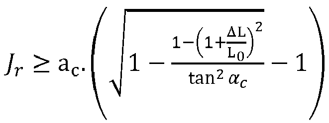
![]()
![]()
Avantageusement, l'angle d'armage de ladite nappe d'armures de traction composites est inférieur ou égal à 25 degrés, de préférence compris entre 10 et 25 degrés.Advantageously, the reinforcement angle of said ply of composite tensile armor is less than or equal to 25 degrees, preferably between 10 and 25 degrees.
De préférence, l'angle d'armage de ladite nappe d'armures de traction métalliques est compris entre 25 et 55 degrés, de préférence compris entre 30 et 55 degrés.Preferably, the winding angle of said ply of metallic tensile armor is between 25 and 55 degrees, preferably between 30 and 55 degrees.
Selon une option de réalisation, lesdites armures de traction composites sont dimensionnées pour un partage des charges axiales entre lesdites nappes d'armures métalliques et composites.According to one embodiment option, said composite tensile armors are dimensioned for a sharing of axial loads between said plies of metallic and composite armors.
Conformément à une mise en œuvre de l'invention, le nombre d'armures de traction composites constituant ladite nappe d'armures de traction composites est contraint par la section, l'angle d'armage et le matériau desdites armures de traction composites, ainsi que par le nombre, la section, l'angle d'armage et le matériau desdites armures de traction métalliques.According to an implementation of the invention, the number of composite tensile armors constituting said layer of composite tensile armors is constrained by the section, the angle of reinforcement and the material of said composite tensile armors, as well only by the number, the section, the angle of reinforcement and the material of said metallic tensile armor.
Selon une caractéristique, le nombre nc d'armures de traction composites constituant ladite nappe d'amures de traction composites est défini par une formule du type : 
![]()
![]()
Conformément à un mode de réalisation, ledit matériau composite est conçu de manière à conférer auxdites nappes d'armures de traction composites un allongement à la rupture au moins égal à l'allongement à la rupture desdites nappes d'armures de traction métalliques.According to one embodiment, said composite material is designed so as to give said composite tensile armor plies an elongation at break at least equal to the elongation at break of said metal tensile armor plies.
De manière avantageuse, ledit matériau composite est un matériau composite à fibres unidirectionnelles.Advantageously, said composite material is a composite material with unidirectional fibers.
Selon une mise en œuvre de l'invention, le module d'Young longitudinal dudit matériau composite est inférieur au module d'Young longitudinal dudit matériau métallique.According to one implementation of the invention, the longitudinal Young's modulus of said composite material is lower than the longitudinal Young's modulus of said metallic material.
Avantageusement, ledit jeu circonférentiel entre une armure de traction composite et un moyen de séparation est compris entre 0,5 et 3 mm.Advantageously, said circumferential clearance between a composite tensile armor and a separation means is between 0.5 and 3 mm.
Conformément à une option de réalisation, lesdits moyens de séparation sont réalisés en matériau polymère.According to one embodiment option, said separation means are made of polymer material.
Selon un mode de réalisation, lesdits moyens de séparation sont formés par des bandes de section sensiblement rectangulaire, lesdites bandes desdits moyens de séparation étant disposées entre lesdites armures de traction composites.According to one embodiment, said separating means are formed by strips of substantially rectangular section, said strips of said separating means being arranged between said composite tensile armor.
Alternativement, lesdits moyens de séparation sont formés par des bandes de section sensiblement en forme de U, lesdites bandes desdits moyens de séparation étant enroulées autour de ladite nappe d'armures de traction métalliques, et une armure de traction composite étant disposée au sein dudit U de chaque moyen de séparation.Alternatively, said separation means are formed by strips of substantially U-shaped section, said strips of said separation means being wound around said ply of metal tensile armor, and a composite tensile armor being placed within said U of each means of separation.
Avantageusement, lesdites armures de traction composites ont une section sensiblement circulaire.Advantageously, said composite tensile armor has a substantially circular section.
De préférence, lesdites armures de traction métalliques ont une section sensiblement rectangulaire.Preferably, said metallic tensile armors have a substantially rectangular section.
Selon une caractéristique, l'élément de renfort mécanique comporte un nombre pair de nappes d'armures métalliques et un nombre pair de nappes d'armures composites.According to one characteristic, the mechanical reinforcement element comprises an even number of metal armor plies and an even number of composite armor plies.
D'autres caractéristiques et avantages du dispositif selon l'invention, apparaîtront à la lecture de la description ci-après d'exemples non limitatifs de réalisations, en se référant aux figures annexées et décrites ci-après.
- La
figure 1 illustre schématiquement en perspective une conduite flexible selon l'art antérieur. - La
figure 2 illustre une conduite flexible selon un premier mode de réalisation de l'invention. - La
figure 3 illustre une conduite flexible selon un deuxième mode de réalisation de l'invention.
- The
figure 1 schematically illustrates in perspective a flexible pipe according to the prior art. - The
picture 2 - The
picture 3
Une conduite flexible selon l'art antérieur est représentée par la
La carcasse interne 1 est constituée d'une bande métallique enroulée selon une hélice à pas court. Elle est destinée à la résistance à l'écrasement sous l'effet de la pression externe appliquée à la conduite.The
La gaine interne d'étanchéité 2 est réalisée par extrusion d'un matériau polymère, en général choisi parmi les polyoléfines, les polyamides et les polymères fluorés.The
La voûte de pression 3 réalisée en fils métalliques agrafés ou emboîtables assure la résistance à la pression interne dans la conduite.The
Selon l'illustration de la
Lorsque les deux nappes superposées et croisées d'armure de traction 4 sont enroulées avec un angle d'hélice sensiblement égal à 55 degrés, la voûte de pression 3 peut optionnellement être supprimée car l'angle d'hélice de 55 degrés confère aux nappes d'armure de traction 4 une bonne résistance à la pression interne.When the two superposed and crossed plies of
La gaine externe d'étanchéité 5 en polymère forme une protection externe de la conduite.The
La conduite représentée par la
Alternativement, la conduite peut être du type "smooth bore". Dans ce cas, la conduite représentée par la
La conduite flexible selon l'invention comporte au moins une gaine de pression et au moins un élément de renfort mécanique. Dans la présente demande, le terme « élément de renfort mécanique » désigne l'ensemble des nappes d'armures (métalliques et composites) utilisées pour reprendre les efforts longitudinaux de la conduite flexible. De plus, la conduite flexible selon l'invention peut avantageusement comporter au moins une des autres couches de la conduite flexible décrites en référence à la
Selon l'invention, l'élément de renfort mécanique comporte au moins une nappe d'amures de traction métalliques et au moins une nappe d'armures de traction composites. Au sein de chaque nappe d'armures de traction, les armures de traction (généralement sous forme de fils ou bandes) sont enroulées en hélice autour de la couche située en-dessous. La nappe d'amure composites est disposée à l'extérieur de la nappe d'armure métalliques. Ainsi, la nappe d'armures de traction composites participe à la reprise des charges axiales de tension : il y a un partage des charges axiales entre la nappe d'armures de traction métalliques et la nappe d'armures de traction composites. Par exemple, la nappe d'armures de traction métalliques est utilisée pour la reprise des efforts de compression au fond, dominés par les fortes pressions, et la nappe d'armures de traction composites est utilisée pour compléter la reprise d'effort de tension en tête de la conduite.According to the invention, the mechanical reinforcement element comprises at least one ply of metallic tensile armor and at least one ply of composite tensile armor. Within each tensile armor ply, the tensile armor (usually in the form of wires or strips) is wound helically around the layer below. The composite tack ply is placed outside the metal armor ply. Thus, the composite tensile armor ply contributes to the absorption of the axial tension loads: there is a sharing of the axial loads between the metal tensile armor ply and the composite tensile armor ply. For example, the sheet of metallic tensile armor is used to take up compressive forces at the bottom, dominated by high pressures, and the sheet of composite tensile armor is used to complete the take-up of tensile forces in driving head.
La conception d'une conduite flexible comprenant à la fois des armures de traction métalliques et des armures de tractions composites, permet de réduire la section et/ou le nombre de nappe d'armures de traction métalliques. Les matériaux composites étant plus légers que les matériaux métalliques, la masse de la conduite flexible est diminuée par rapport à une conception comprenant uniquement des armures de traction métalliques.The design of a flexible pipe comprising both metallic tensile armors and composite tensile armors makes it possible to reduce the section and/or the number of sheets of metallic tensile armors. Since composite materials are lighter than metallic materials, the mass of the flexible pipe is reduced compared to a design comprising only metallic tensile armor.
En outre, selon l'invention, des moyens de séparation séparent les armures de traction composites, en maintenant un jeu radial et un jeu circonférentiel. Dans la présente demande, l'expression « jeu radial » désigne la possibilité de mouvement de l'armure de traction composite selon une direction confondue avec le rayon de la conduite flexible, et le jeu radial est dirigé vers l'extérieur à la conduite. En d'autres termes, les armures de traction composites peuvent s'éloigner du centre de la conduite flexible. Dans la présente demande, l'expression « jeu circonférentiel » désigne la possibilité de mouvement de l'armure de traction composite selon une direction périphérique. En d'autres termes, les armures de traction composites peuvent se déplacer selon un arc de cercle dont le centre est l'axe de la conduite flexible.Furthermore, according to the invention, separation means separate the composite tensile armor, maintaining a radial clearance and a circumferential clearance. In the present application, the expression “radial clearance” denotes the possibility of movement of the composite tensile armor in a direction coinciding with the radius of the flexible pipe, and the radial clearance is directed towards the outside of the pipe. In other words, the composite tensile armor can pull away from the center of the flexible pipe. In the present application, the expression "circumferential clearance" designates the possibility of movement of the composite tensile armor in a peripheral direction. In other words, the composite tensile armor can move along an arc of a circle whose center is the axis of the flexible pipe.
Les jeux sont permis par la forme et par la disposition des moyens de séparation. En particulier, le jeu radial est permis par la hauteur des moyens de séparation, qui est supérieure à la hauteur des armures de traction composites. Le jeu circonférentiel peut être permis par le fait que les moyens de séparation n'occupent pas la totalité de l'espacement circonférentiel entre deux armures de traction composites consécutives. Ces jeux permettent aux armures de traction composites de se déplacer radialement sous le chargement de compression axiale de la conduite flexible. Ainsi, la nappe d'armures de traction composites est libre de s'étendre radialement de manière à compenser la réduction axiale de la conduite sous l'effet de la pression externe. En conséquence, les contraintes de compression axiale sont minimisées dans les armures de traction composites, les armures de traction composites peuvent donc être utilisées dans des conditions de pressions importantes.Games are permitted by the shape and by the arrangement of the means of separation. In particular, the radial play is permitted by the height of the separation means, which is greater than the height of the composite tensile armor. The circumferential play can be allowed by the fact that the separation means do not occupy the whole of the spacing circumferential between two consecutive composite tensile armors. These clearances allow the composite tensile armor to move radially under the axial compression loading of the flexible pipe. Thus, the ply of composite tensile armor is free to extend radially so as to compensate for the axial reduction of the pipe under the effect of the external pressure. As a result, axial compressive stresses are minimized in composite tensile armor, so composite tensile armor can be used under high pressure conditions.
De manière avantageuse, le jeu radial peut être supérieur au jeu circonférentiel, afin de permettre aux armures de traction composites de se déplacer essentiellement radialement.Advantageously, the radial clearance can be greater than the circumferential clearance, in order to allow the composite tensile armor to move essentially radially.
Dans la présente demande, les termes « armures de traction composites » et « armures composites » ont la même signification et sont utilisés indifféremment. De même, les termes « armures de traction métalliques » et « armures métalliques » ont la même signification et sont utilisés indifféremment.In the present application, the terms "composite tensile armor" and "composite armor" have the same meaning and are used interchangeably. Likewise, the terms "metal tensile armor" and "metal armor" have the same meaning and are used interchangeably.
Conformément à une mise en œuvre de l'invention, des jeux circonférentiels peuvent être prévus entre les armures métalliques, afin d'obtenir une bonne souplesse en flexion.According to one implementation of the invention, circumferential clearances can be provided between the metal armours, in order to obtain good bending flexibility.
En revanche, afin de conserver la résistance aux pressions internes et externes, aucun jeu radial n'est prévu pour les armures métalliques. Par exemple, les armures métalliques peuvent être posés sous tension, et une bande de maintien à résistance mécanique élevée renforcée avec des fibres d'aramide peut venir les maintenir radialement. Par exemples, les fibres d'aramide sont choisies parmi les références commerciales Kevlar ®, Twaron ® ou encore Technora ®.On the other hand, in order to preserve the resistance to internal and external pressures, no radial clearance is provided for the metal armours. For example, the metal armor can be placed under tension, and a high mechanical resistance support band reinforced with aramid fibers can hold them radially. For example, the aramid fibers are chosen from the commercial references Kevlar ® , Twaron ® or even Technora ® .
De préférence, l'élément de renfort mécanique comporte un nombre pair de nappes d'armures de traction métalliques et un nombre pair de nappes d'armures de traction composites. Avantageusement, les nappes d'amures de traction d'une paire de nappes sont croisées, en d'autres termes elles sont posées avec des angles d'armage (c'est-à-dire l'angle d'hélice de l'enroulement des armures de traction) de signes opposés. Par exemple, si la nappe interne d'armures de traction est posée avec un angle d'armage (angle d'hélice) égal à 30 degrés, la nappe externe d'armures de traction est enroulée avec un angle d'armage (angle d'hélice) égal à -30 degrés. Cette symétrie angulaire permet d'équilibrer la conduite en torsion, de façon à réduire sa tendance à tourner sous l'effet d'un effort de traction.Preferably, the mechanical reinforcement element comprises an even number of metal tensile armor plies and an even number of composite tensile armor plies. Advantageously, the tensile tack plies of a pair of plies are crossed, in other words they are laid with winding angles (i.e. the helix angle of the winding tensile weaves) of opposite signs. For example, if the inner tensile armor ply is laid with a lay angle (helix angle) equal to 30 degrees, the outer tensile armor ply is wound with a lay angle (angle d helix) equal to -30 degrees. This angular symmetry makes it possible to balance the pipe in torsion, so as to reduce its tendency to turn under the effect of a tensile force.
Par exemple, l'élément de renfort mécanique peut comprendre de l'intérieur vers l'extérieur deux nappes d'armures de traction métalliques, et deux nappes d'armures de traction composites. Cette conception permet un bon compromis entre la masse de la conduite flexible et la résistance aux pressions interne et externe.For example, the mechanical reinforcement element may comprise, from the inside outwards, two plies of metal tensile armor, and two plies of composite traction. This design allows a good compromise between the mass of the flexible pipe and the resistance to internal and external pressures.
Lors de la fabrication de la conduite flexible, la pose en hélice des armures de traction en matériau composite peut générer une contrainte élastique de flexion. En effet, plus l'angle d'armage (c'est-à-dire l'angle d'hélice de l'enroulement des armures de traction) est élevé, plus la courbure de l'hélice est importante et plus cette contrainte de pose est forte. Afin de limiter la contrainte d'assemblage, il est donc intéressant d'utiliser des angles d'armage faibles pour les nappes d'armures composites par comparaison aux angles couramment utilisés sur les nappes d'armures métalliques. Les angles d'armage des nappes d'armures composites sont donc de préférence inférieurs ou égaux à 25 degrés, préférentiellement compris entre 10 et 25 degrés, pour limiter la contrainte élastique de flexion au sein des armures de traction composites.During the manufacture of the flexible pipe, the helical laying of the composite material tensile armor can generate an elastic bending stress. Indeed, the higher the winding angle (i.e. the helix angle of the winding of the tensile armor), the greater the curvature of the helix and the greater this stress of pose is strong. In order to limit the assembly stress, it is therefore beneficial to use low reinforcing angles for composite armor plies compared to the angles commonly used on metal armor plies. The reinforcement angles of the composite armor plies are therefore preferably less than or equal to 25 degrees, preferably between 10 and 25 degrees, to limit the elastic bending stress within the composite tensile armor.
Les angles d'armage des nappes d'armure métalliques de la conduite flexible selon une mise en œuvre de l'invention sont, de manière classique, compris entre 25 et 55 degrés, de préférence compris entre 30 et 55 degrés.The reinforcing angles of the metal armor plies of the flexible pipe according to an implementation of the invention are, conventionally, between 25 and 55 degrees, preferably between 30 and 55 degrees.
Les armures de traction métalliques peuvent être réalisées notamment en acier, par exemple en acier inoxydable, en acier austéno-ferritique (ou acier « Duplex ») ou par exemple à partir d'aciers au carbone faiblement alliés. Les armures de traction métalliques peuvent être aussi des profils tréfilés à froid.The metal tensile armor can be made in particular of steel, for example stainless steel, austenitic-ferritic steel (or “Duplex” steel) or for example from low-alloy carbon steels. Metal tensile armor can also be cold drawn profiles.
En variante, les armures de traction métalliques sont réalisées en titane ou à partir d'un alliage de titane.As a variant, the metallic tensile armors are made of titanium or from a titanium alloy.
Les armures de traction composites peuvent être réalisées dans une résine thermoplastique ou thermodurcissable contenant des fibres de renfort.Composite tensile armor can be made from a thermoplastic or thermosetting resin containing reinforcing fibers.
Par exemple, la résine thermoplastique est à base d'une polyoléfine telle que du polyéthylène, à base d'un polyamide tel que du PA11 ou du PA12, ou à base d'un polymère fluoré tel que du polyfluorure de vinylidène (PVDF) ou du perfluoroalkoxy (PFA). En variante, la résine est formée à base d'un polymère haute performance tel que le PEK (polyéthercétone), le PEEK (polyétheréthercétone), le PEEKK (polyétheréthercétonecétone), le PEKK (polyéthercétonecétone), le PEKEKK (polyéthercétoneéthercétonecétone), le PAI (polyamide-imide), le PEI (polyéther-imide), le PSU (polysulfone), le PPSU (polyphénylsulfone), le PES (polyéthersulfone), le PAS (polyarylsulfone), le PPE (polyphénylèneéther), le PPS (polysulfure de phénylène) les LCP (polymères à cristaux liquides), le PPA (polyphtalamide) et/ou leurs mélanges ou encore en mélange avec le PTFE (polytétrafluoroéthylène) ou le PFPE (perfluoropolyéther).For example, the thermoplastic resin is based on a polyolefin such as polyethylene, based on a polyamide such as PA11 or PA12, or based on a fluorinated polymer such as polyvinylidene fluoride (PVDF) or perfluoroalkoxy (PFA). Alternatively, the resin is formed from a high performance polymer such as PEK (polyetherketone), PEEK (polyetheretherketone), PEEKK (polyetheretherketoneketone), PEKK (polyetherketoneketone), PEKEKK (polyetheretherketoneketone), PAI ( polyamide-imide), PEI (polyether-imide), PSU (polysulfone), PPSU (polyphenylsulfone), PES (polyethersulfone), PAS (polyarylsulfone), PPE (polyphenyleneether), PPS (polyphenylene sulfide) LCPs (liquid crystal polymers), PPA (polyphthalamide) and/or mixtures thereof or else mixed with PTFE (polytetrafluoroethylene) or PFPE (perfluoropolyether).
Par exemple, la résine thermodurcissable est à base d'une résine époxyde (EP), une résine polyester (UP), une résine vinylester (VE), une résine polyuréthanne (PUR) ou encore une résine phénolique (PF).For example, the thermosetting resin is based on an epoxy resin (EP), a polyester resin (UP), a vinylester resin (VE), a polyurethane resin (PUR) or even a phenolic resin (PF).
Les fibres de renfort peuvent être choisies parmi les fibres minérales ou les fibres synthétiques. De préférence, les fibres utilisées sont des fibres de verre et/ou des fibres de carbone. En variante, les fibres de renfort sont des fibres synthétiques telles que des fibres en polyéthylène, en polyester ou polyamide, ou bien des fibres minérales telles que des fibres de basalte.The reinforcing fibers can be chosen from mineral fibers or synthetic fibers. Preferably, the fibers used are glass fibers and/or carbon fibers. Alternatively, the reinforcing fibers are synthetic fibers such as polyethylene, polyester or polyamide fibers, or mineral fibers such as basalt fibers.
Par exemple, les armures peuvent être réalisées en matériau composite à fibres unidirectionnelles, obtenu par exemple par pultrusion, comprenant sensiblement 60% de fibres de carbone dans une résine époxyde. Les armures de traction composites peuvent être, par exemple, réalisées avec des fibres de renfort en carbone T700 commercialisées par Toray Carbon Fibers, USA. D'autres fibres de carbone telles que les fibres TR50 commercialisées par Mitsubishi Rayon Co., les fibres UTS50 commercialisées par Teijin ou encore les fibres AS4 commercialisées par Hexcel.For example, the armor can be made of a composite material with unidirectional fibers, obtained for example by pultrusion, comprising substantially 60% carbon fibers in an epoxy resin. The composite tensile armor can be, for example, made with T700 carbon reinforcing fibers marketed by Toray Carbon Fibers, USA. Other carbon fibers such as TR50 fibers marketed by Mitsubishi Rayon Co., UTS50 fibers marketed by Teijin or alternatively AS4 fibers marketed by Hexcel.
Dans une autre variante de réalisation de l'invention, les armures composites sont des armures de type « cordes » réalisées à partir d'un tressage de plusieurs torons de fibres, les fibres n'étant pas noyées dans une résine thermoplastique ou thermodurcissable. Les fibres utilisées pour réaliser ce type d'armure sont par exemple choisies parmi les fibres synthétiques telles que des fibres en polyéthylène, en polyester, en carbone ou polyamide, ou bien les fibres minérales telles que des fibres de basalte. Les torons sont réalisés à partir de fibres de même nature ou bien à partir d'un mélange de différentes fibres.In another alternative embodiment of the invention, the composite weaves are “cord” type weaves made from braiding several strands of fibers, the fibers not being embedded in a thermoplastic or thermosetting resin. The fibers used to produce this type of armor are for example chosen from synthetic fibers such as fibers made of polyethylene, polyester, carbon or polyamide, or mineral fibers such as basalt fibers. The strands are made from fibers of the same nature or from a mixture of different fibers.
Avantageusement, l'utilisation d'armures de type « cordes » permet d'obtenir de bonnes propriétés de résistance mécanique en compression du fait que les fibres ne sont pas contraintes par la présence d'une résine thermoplastiques ou thermodurcissable.Advantageously, the use of armor of the “cord” type makes it possible to obtain good mechanical resistance properties in compression because the fibers are not constrained by the presence of a thermoplastic or thermosetting resin.
Les moyens de séparation peuvent être réalisés en matériau polymère, par exemple en polymère thermoplastique tel qu'un polyoléfine (PE, PP), un polyamide (PA11, PA12) ou un polymère fluoré (PVDF, PFA), en polymère thermodurcissable tel qu'un polyuréthanne ou encore en élastomèreAinsi, les moyens de séparation sont réalisés dans un matériau léger (plus léger que les armures de traction), qui limite l'augmentation de la masse de la conduite flexible.The separation means can be made of a polymer material, for example a thermoplastic polymer such as a polyolefin (PE, PP), a polyamide (PA11, PA12) or a fluorinated polymer (PVDF, PFA), a thermosetting polymer such as a polyurethane or even an elastomer. Thus, the separation means are made of a light material (lighter than the tensile armor), which limits the increase in the mass of the flexible pipe.
Selon un exemple de réalisation de l'invention, les armures de traction métalliques peuvent avoir une section sensiblement rectangulaire. On désigne la section d'une armure de traction, une vue selon une coupe orthogonale à la direction de la longueur de l'armure de traction. De cette manière, il est possible d'utiliser les armures utilisées classiquement.According to an exemplary embodiment of the invention, the metal tensile armor may have a substantially rectangular section. We denote the section of a tensile armor, a view according to a section orthogonal to the direction of the length of the tensile armor. In this way, it is possible to use the armors used conventionally.
Alternativement, la section des armures de traction métalliques peut être de toute forme, par exemple circulaire, elliptique, etc.Alternatively, the section of the metal tensile armor can be of any shape, for example circular, elliptical, etc.
Selon un exemple de réalisation de l'invention, les armures de traction composites peuvent avoir une section sensiblement circulaire. Ainsi, il est possible d'utiliser des armures de traction de section circulaire peu onéreuses déjà commercialisées pour d'autres applications sous-marines telles que pour les câbles sous-marins, les ombilicaux sous-marins ou encore les tendons d'ancrage de plateforme pétrolière. Par exemple, ce type d'armure est réalisé sous la forme d'un élément de renfort de grande longueur obtenu par pultrusion, comportant des fibres longitudinales en carbone noyées dans une matrice polymérique.According to an exemplary embodiment of the invention, the composite tensile armor may have a substantially circular section. Thus, it is possible to use inexpensive circular section tensile armor already marketed for other submarine applications such as for submarine cables, submarine umbilicals or even platform anchoring tendons. petroleum. For example, this type of armor is produced in the form of a very long reinforcing element obtained by pultrusion, comprising longitudinal carbon fibers embedded in a polymer matrix.
Selon une variante, ce type d'armure peut également se présenter sous la forme d'un noyau réalisé à partir d'un groupement d'éléments de renfort de grande longueur du type de ceux décrit ci-avant, le noyau étant recouvert d'une couche de fibres tressées selon un angle prédéfini pour les maintenir ensemble.According to a variant, this type of armor can also be in the form of a core made from a group of very long reinforcing elements of the type described above, the core being covered with a layer of braided fibers at a predefined angle to hold them together.
Alternativement, la section des armures de traction composites peut être de toute forme, par exemple rectangulaire, elliptique, etc.Alternatively, the section of the composite tensile armor can be of any shape, for example rectangular, elliptical, etc.
Selon un premier mode de réalisation de l'invention, les moyens de séparation peuvent être formés, par des bandes de section sensiblement rectangulaire. Pour ce mode de réalisation les bandes sont disposées entre les armures de traction composites. En d'autres termes, la nappe d'armures de traction composites est formée d'une alternance d'armures de traction composites et de moyens de séparation. Ce mode de réalisation est simple à réaliser. La hauteur de la section des moyens de séparation peut être supérieure à la hauteur des armures de traction composites, de manière à assurer le jeu radial. De plus, l'épaisseur des moyens de séparation est inférieure à la distance circonférentielle entre deux armures de traction composites consécutives, de manière à assurer le jeu circonférentiel.According to a first embodiment of the invention, the separation means can be formed by strips of substantially rectangular section. For this embodiment, the strips are placed between the composite tensile armors. In other words, the ply of composite tensile armor is formed by alternating composite tensile armor and separation means. This embodiment is simple to perform. The height of the section of the separation means may be greater than the height of the composite tensile armor, so as to ensure the radial play. In addition, the thickness of the separating means is less than the circumferential distance between two consecutive composite tensile armor layers, so as to ensure circumferential play.
Selon un deuxième mode de réalisation de l'invention, les moyens de séparation peuvent être formés par des bandes de section sensiblement en forme de U, le U étant ouvert vers l'extérieur de la conduite flexible. Pour ce mode de réalisation, les bandes des moyens de séparation peuvent être enroulées autour de la nappe d'armures de traction métalliques, et une armure de traction composite est disposée au sein de chaque U des moyens de séparation. En d'autres termes, la nappe d'armures de traction composites est formée d'une suite de moyens de séparation U, au sein desquels sont disposés des armures de traction composites. Ce mode de réalisation est notamment adapté lorsque les pressions de contact entre les nappes d'armures de traction sont élevées. En effet, la forme en U permet une meilleure répartition de l'effort de contact et donc de réduire la pression de contact. La hauteur des branches du U peut assurer le jeu radial, et l'espacement entre les branches du U peut assurer le jeu circonférentiel.According to a second embodiment of the invention, the separation means can be formed by strips of substantially U-shaped section, the U being open towards the outside of the flexible pipe. For this embodiment, the strips of the separation means can be wound around the ply of metal tensile armor, and a composite tensile armor is placed within each U of the separation means. In other words, the ply of composite tensile armor is formed from a series of separation means U, within which are arranged composite tensile armor. This embodiment is particularly suitable when the contact pressures between the tensile armor plies are high. In fact, the U-shape allows a better distribution of the contact force and therefore to reduce the contact pressure. The height of the branches of the U can ensure the radial clearance, and the spacing between the branches of the U can ensure the circumferential clearance.
Conformément à une mise en œuvre de l'invention, le jeu circonférentiel entre une armure composite et un moyen de séparation est compris entre 0,5 et 3 mm. Avantageusement, le jeu circonférentiel peut être d'environ 1 mm. Ainsi, l'armure de traction composite peut avoir un déplacement circonférentiel total de 2 mm (1 mm dans chaque direction circonférentielle).According to one implementation of the invention, the circumferential clearance between a composite armor and a separation means is between 0.5 and 3 mm. Advantageously, the circumferential play can be around 1 mm. Thus, the composite tensile armor can have a total circumferential displacement of 2mm (1mm in each circumferential direction).
Selon un mode de réalisation de l'invention, une couche intermédiaire peut être prévue entre les nappes acier et composite. Cette couche intermédiaire a pour fonction de bloquer le gonflement de l'armure métallique en compression. Selon un exemple de réalisation, la couche intermédiaire est une bande de maintien à résistance mécanique élevée renforcée avec des fibres d'aramide peut venir les maintenir. Par exemples, les fibres d'aramide sont choisies parmi les références commerciales Kevlar ®, Twaron ® ou encore Technora ® According to one embodiment of the invention, an intermediate layer may be provided between the steel and composite layers. This intermediate layer has the function of blocking the swelling of the metal armor in compression. According to an exemplary embodiment, the intermediate layer is a high-strength holding band reinforced with aramid fibers that can hold them. For example, the aramid fibers are chosen from the commercial references Kevlar ® , Twaron ® or even Technora ®
Avantageusement, des bandes anti-usure peuvent être prévues entre les armures métalliques, afin d'éviter l'usure des armures métalliques.Advantageously, anti-wear strips can be provided between the metal armours, in order to prevent wear of the metal armours.
Selon une caractéristique de l'invention, des rubans de maintien peuvent être prévus entre chaque paire de nappes.According to one characteristic of the invention, retaining tapes can be provided between each pair of plies.
Selon un mode de réalisation de l'invention, les nappes d'armures de traction métalliques sont dimensionnées pour résister aux chargements en pied de conduite flexible (pression externe, courbure), avec les méthodes classiques. La tension en tête de conduite flexible peut être alors estimée à partir du poids propre de la conduite flexible en négligeant la masse des nappes composites - hypothèse vérifiée a posteriori - et de l'effet de fond en cas de pressurisation interne. On suppose que les nappes d'armures de traction métalliques ainsi dimensionnées n'ont pas la capacité suffisante pour reprendre l'intégralité de cette tension notée FTOT.According to one embodiment of the invention, the metal tensile armor plies are dimensioned to resist the loads at the foot of the flexible pipe (external pressure, curvature), with conventional methods. The tension at the head of the flexible pipe can then be estimated from the self-weight of the flexible pipe, neglecting the mass of the composite plies - hypothesis verified a posteriori - and from the bottom effect in the event of internal pressurization. It is assumed that the metal tensile armor layers thus dimensioned do not have sufficient capacity to take up all of this tension noted F TOT .
Dans une approche de conception simplifiée, les nappes d'armures composites peuvent être dimensionnées par paire, dite bi-nappes, à angles d'armage opposés, et positionnées à un rayon moyen ac déduit du rayon des nappes d'armures de traction métalliques.In a simplified design approach, the composite armor plies can be dimensioned in pairs, called bi-plies, with opposite reinforcing angles, and positioned at an average radius a c deduced from the radius of the metal tensile armor plies .
Le calcul de la section totale des armures composite nécessaires se base sur le principe d'un partage des charges axiales entre les nappes d'armures. Les efforts Fa et Fc dans les bi-nappes métallique et composite sont proportionnels à leurs raideurs axiales respectives Ka et Kc, selon l'allongement global ![]()
![]()
![]()
![]()
Les raideurs axiales dépendent de la géométrie de la bi-nappe et du module de Young du matériau : ![]()
i l'indice associé à la bi-nappe (i=a pour métal, i=c pour le composite),
- E le module de Young longitudinal du matériau,
- n le nombre de fil d'armure,
- S la section d'un fil d'armure,
- αi l'angle d'armage.
i the index associated with the bi-ply (i=a for metal, i=c for composite),
- E the longitudinal Young's modulus of the material,
- n the number of armor wires,
- S the section of an armor wire,
- α i the lay angle.
Les efforts axiaux dans chaque bi-nappe sont fonction de la contrainte de traction ![]()
![]()
![]()
![]()
En injectant les équations 2 et 3 dans l'équation Eq. 11 pour chaque bi-nappe, on obtient une relation entre la contrainte dans les fils et la raideur de la bi-nappe d'armures composites. ![]()
![]()
Les contraintes dans les fils doivent respecter un critère de résistance du matériau. Dans les fils d'acier, la contrainte de traction ![]()
![]()
![]()
![]()
![]()
![]()
Dans les armures de traction composites, la somme de la contrainte de traction ![]()
![]()
![]()
![]()
![]()
- ac le rayon moyen de la bi-nappe d'armures composite,
- hc la distance maximale à la fibre neutre en flexion de l'armure de traction composite (égale au rayon rc de l'armure de traction composite dans le cas d'une armure de traction composite de section circulaire).
- a c the average radius of the composite armor bi-ply,
- h c the maximum distance to the neutral fiber in bending of the composite tensile armor (equal to the radius r c of the composite tensile armor in the case of a composite tensile armor of circular section).
La contrainte dans les fils d'armures est extraite de l'expression 4 puis injectée dans les critères matériaux exprimés dans les équations 5 et 6. Pour les fils d'armures métalliques : ![]()
![]()
Pour les armures composites : ![]()
![]()
On obtient donc une valeur minimale à respecter pour la raideur de la bi-nappe d'armures composites : ![]()
![]()
Selon un mode de réalisation de l'invention, pour un angle d'armage αc choisi (préférentiellement dans la plage indiquée précédemment, c'est-à-dire inférieur ou égale à 25 degrés) et un matériau composite donné, on en déduit le nombre de d'armures composite nc optimal à utiliser dans la bi-nappe d'armures composite en fonction de la section Sc d'une armure : 
Pour différentes sections d'armures de traction composites disponibles, on peut vérifier que le nombre d'armures de traction est compatible avec la place laissée disponible sur le périmètre de la nappe après mise en place d'un nombre identique des moyens de séparation et ménagement d'un jeu circonférentiel prédéterminé (par exemple un jeu circonférentiel d'environ 1 mm) entre les moyens de séparation et les armures de traction composites. Il existe potentiellement plusieurs couples (nc,Sc) solutions. Idéalement, on souhaite des moyens de séparation larges pour assurer une bonne stabilité de l'assemblage.For different sections of composite tensile armors available, it can be checked that the number of tensile armors is compatible with the space left available on the perimeter of the ply after installation of an identical number of means of separation and a predetermined circumferential clearance (for example a circumferential clearance of about 1 mm) between the separating means and the composite tensile armor. There are potentially several pairs (n c ,S c ) solutions. Ideally, wide separation means are desired to ensure good stability of the assembly.
La compression dans les nappes d'armures composites peut être évitée en permettant aux armures composites de maintenir une longueur constante. La contraction axiale est compensée par un déplacement radial autorisé grâce à un jeu radial au-dessus des armures composites, maintenu par les moyens de séparation. Connaissant la raideur axiale en compression de la conduite flexible, conférée par les nappes aciers, il est possible d'estimer le taux de contraction axiale ![]()

![]()
![]()
![]()
Ainsi, le jeu radial Jr , et a fortiori la hauteur des moyens de séparation, peut être déterminé au moyen d'une équation du type : Par conséquent, 
![]()
![]()
Il est également souhaitable que le matériau composite choisi confère aux nappes d'armures composites un allongement à la rupture au moins égal à l'allongement à la rupture des nappes d'armures métalliques. A partir des équations précédentes, ce critère sur les allongements à rupture des nappes s'écrit : ![]()
![]()
On en déduit un allongement à rupture optimal pour le matériau composite : 
Conformément à un mode de réalisation de l'invention, le matériau composite des armures composites peut être choisi de manière à vérifier un critère de choix portant sur son allongement à rupture, qui doit être idéalement égal à l'allongement optimal, 
La
La
La présente invention est adaptée pour les conduites flexibles de type « riser » et pour les conduites flexibles de type « flowline ».The present invention is suitable for flexible pipes of the “riser” type and for flexible pipes of the “flowline” type.
L'invention est particulièrement adaptée à une conduite flexible pour les grandes profondeurs, pour laquelle la tension en tête de la conduite est le chargement le plus sévère pour le dimensionnement des armures.The invention is particularly suited to a flexible pipe for great depths, for which the tension at the head of the pipe is the most severe loading for the dimensioning of the armor.
Les caractéristiques et avantages de la conduite flexible selon l'invention apparaîtront plus clairement à la lecture de l'exemple d'application ci-après.The characteristics and advantages of the flexible pipe according to the invention will appear more clearly on reading the application example below.
Cet exemple d'application concerne une conduite flexible de type flowline pour 2500m de profondeur d'eau dont le chargement dimensionnant pour les armures est la tension en tête à l'installation, avec un chargement extrême en tête à l'installation de 4300kN, correspondant au poids propre affecté d'un coefficient 1.25. Pour la solution actuelle (selon l'art antérieur), l'élément de renfort mécanique est constitué de :
- deux nappes d'armures en acier au carbone présentant une haute résistance mécanique supérieure ou égale à 1200 MPa de respectivement 64 et 66 fils de section 14×6 mm2 armées à 25 degrés.
- two layers of carbon steel armor having a high mechanical strength greater than or equal to 1200 MPa of respectively 64 and 66 wires with a 14×6 mm 2 cross-section reinforced at 25 degrees.
Grâce à la conception de la conduite flexible selon l'invention, il est possible de dimensionner la section d'acier pour les chargements en fond uniquement, c'est-à-dire la pression externe et flambage. Pour le même chargement extrême défini ci-dessus, on peut dimensionner une conduite flexible selon l'invention avec un élément de renfort mécanique constitué de :
- deux nappes d'armures en acier au carbone présentant une haute résistance mécanique supérieure ou égale à 1200 MPa de respectivement 64 et 66 fils de section 12×3 mm2 armées à 25 degrés,
- deux nappes d'armures composites de respectivement 50 et 52 fils de diamètre 6 mm espacés avec un nombre identique de moyens de séparation de section 11×9.6 mm2, armées à 15 degrés, de plus :
- les armures composites sont en composite à 60% de fibres de carbone (type T700 de Toray) dans une résine époxyde,
- les moyens de séparation sont en polypropylène PP (type ELTEX® TUB350 de Solvay Plastics).
- two layers of carbon steel armor having a high mechanical resistance greater than or equal to 1200 MPa of respectively 64 and 66 wires with a 12×3 mm 2 cross-section reinforced at 25 degrees,
- two layers of composite armor of respectively 50 and 52 wires with a diameter of 6 mm spaced with an identical number of separation means with a section of 11×9.6 mm 2 , reinforced at 15 degrees, in addition:
- the composite armors are made of 60% carbon fiber composite (type T700 from Toray) in an epoxy resin,
- the separation means are made of polypropylene PP (type ELTEX® TUB350 from Solvay Plastics).
Cette conception est réalisée selon le mode de réalisation de la
Le calcul des raideurs axiales des nappes indique un partage de charges axiales de 70% dans les armures aciers et 30% dans les armures composites.The calculation of the axial stiffnesses of the layers indicates an axial load sharing of 70% in the steel armor and 30% in the composite armor.
Le gain de poids est de 52 kg/m dans l'air, 45 kg/m dans l'eau conduite pleine. Ce gain de poids est permis car la section des nappes d'armures en acier a été divisé par deux par rapport à la solution actuelle selon l'art antérieur.Weight gain is 52 kg/m in air, 45 kg/m in full water. This weight gain is permitted because the section of the steel armor plies has been halved compared to the current solution according to the prior art.
Ainsi, la conception des nappes d'armures d'une conduite flexible selon l'invention permet une diminution significative de la masse de la conduite flexible, tout en conservant une flexibilité, et une résistance mécanique aux chargements en pressions internes et externes. Sa flexibilité étant conservée, il est possible d'enrouler la conduite flexible sur une bobine de stockage avec un rayon d'enroulement similaire à celui d'une conduite flexible classique sans nappes d'armures composites.Thus, the design of the armor plies of a flexible pipe according to the invention allows a significant reduction in the mass of the flexible pipe, while retaining flexibility and mechanical resistance to internal and external pressure loads. Its flexibility being retained, it is possible to wind the flexible pipe on a storage reel with a winding radius similar to that of a conventional flexible pipe without layers of composite armor.
Claims (17)
- Flexible pipe for transporting a petroleum effluent, said pipe comprising at least one mechanical reinforcement element (4) and a pressure sheath (2), said mechanical reinforcement element (4) being disposed outside of said pressure sheath, said mechanical reinforcement element comprising at least one metal tensile armour layer (6) and at least one composite tensile armour layer (7), said composite tensile armour layer (7) being disposed outside of said metal tensile armour layer (6), characterized in that separation means (8; 10) separate said composite tensile armours (7), said separation means (8; 10) ensuring a radial play and a circumferential play for said composite tensile armours (7).
- Pipe according to Claim 1, wherein said radial play J r of said composite tensile armours (7) is determined according to an equation of the type:


- Pipe according to one of the preceding claims, wherein the lay angle of said composite tensile armour layer (7) is less than or equal to 25 degrees, preferably between 10 and 25 degrees.
- Pipe according to one of the preceding claims, wherein the lay angle of said metal tensile armour layer (6) is between 25 and 55 degrees, preferably between 30 and 55 degrees.
- Pipe according to one of the preceding claims, wherein said composite tensile armours (7) are dimensioned for a sharing of the axial loads between said metal (6) and composite (7) armour layers.
- Pipe according to one of the preceding claims, wherein the number of composite tensile armours (7) forming said composite tensile armour layer is dictated by the section, the lay angle and the material of said composite tensile armours (7) and by the number, the section, the lay angle and the material of said metal tensile armours (6).
- Pipe according to one of the preceding claims, wherein the number n c of composite tensile armours (7) forming said composite tensile armour layer is defined by a formula of the type:


- Pipe according to one of the preceding claims, wherein said composite material is designed so as to confer on said composite tensile armour layers (7) an elongation at break at least equal to the elongation at break of said metal tensile armour layers (6).
- Pipe according to one of the preceding claims, wherein said composite material is a composite material with unidirectional fibres.
- Pipe according to one of the preceding claims, wherein the longitudinal Young's modulus of said composite material is less than the longitudinal Young's modulus of said metal material.
- Pipe according to one of the preceding claims, wherein said circumferential play between a composite tensile armour (7) and a separation means (8; 10) is between 0.5 and 3 mm.
- Pipe according to one of the preceding claims, wherein said separation means (8; 10) are made of polymer material.
- Pipe according to one of the preceding claims, wherein said separation means (8) are formed by strips of substantially rectangular section, said strips of said separation means (8) being disposed between said composite tensile armours (7).
- Pipe according to one of the preceding claims, wherein said separation means (10) are formed by strips of substantially U-shaped section, said strips of said separation means (10) being wound around said metal tensile armour layer (6) and a composite tensile armour (7) being disposed within said U of each separation means (10).
- Pipe according to one of the preceding claims, wherein said composite tensile armours (7) have a substantially circular section.
- Pipe according to one of the preceding claims, wherein said metal tensile armours (6) have a substantially rectangular section.
- Pipe according to one of the preceding claims, wherein the mechanical reinforcement element comprises an even number of metal armour layers (6) and an even number of composite armour layers (7).
Applications Claiming Priority (2)
| Application Number | Priority Date | Filing Date | Title |
|---|---|---|---|
| FR1752748A FR3064711B1 (en) | 2017-03-31 | 2017-03-31 | FLEXIBLE DRIVING WITH METAL ARMOR NAPES AND COMPOSITE ARMOR NAPES |
| PCT/EP2018/056143 WO2018177735A1 (en) | 2017-03-31 | 2018-03-13 | Flexible pipe with layers of metal armour and layers of composite armour |
Publications (2)
| Publication Number | Publication Date |
|---|---|
| EP3601862A1 EP3601862A1 (en) | 2020-02-05 |
| EP3601862B1 true EP3601862B1 (en) | 2022-05-11 |
Family
ID=58707908
Family Applications (1)
| Application Number | Title | Priority Date | Filing Date |
|---|---|---|---|
| EP18709605.2A Active EP3601862B1 (en) | 2017-03-31 | 2018-03-13 | Flexible pipe with layers of metal armour and layers of composite armour |
Country Status (6)
| Country | Link |
|---|---|
| US (1) | US11047512B2 (en) |
| EP (1) | EP3601862B1 (en) |
| BR (1) | BR112019020051B1 (en) |
| DK (1) | DK3601862T3 (en) |
| FR (1) | FR3064711B1 (en) |
| WO (1) | WO2018177735A1 (en) |
Families Citing this family (19)
| Publication number | Priority date | Publication date | Assignee | Title |
|---|---|---|---|---|
| NO2304299T3 (en) | 2008-06-09 | 2018-03-03 | ||
| SG11201702590SA (en) | 2014-09-30 | 2017-04-27 | Flexsteel Pipeline Technologies Inc | Connector for pipes |
| MX2018005527A (en) | 2015-11-02 | 2018-08-16 | Flexsteel Pipeline Tech Inc | Real time integrity monitoring of on-shore pipes. |
| US10981765B2 (en) | 2016-06-28 | 2021-04-20 | Trinity Bay Equipment Holdings, LLC | Half-moon lifting device |
| US11208257B2 (en) | 2016-06-29 | 2021-12-28 | Trinity Bay Equipment Holdings, LLC | Pipe coil skid with side rails and method of use |
| CN109996749B (en) | 2016-10-10 | 2021-01-12 | 圣三一海湾设备控股有限公司 | Installation trailer for coiled flexible pipe and method of use thereof |
| CN113086775A (en) | 2016-10-10 | 2021-07-09 | 圣三一海湾设备控股有限公司 | Roller assembly |
| US10526164B2 (en) | 2017-08-21 | 2020-01-07 | Trinity Bay Equipment Holdings, LLC | System and method for a flexible pipe containment sled |
| EA202091764A1 (en) | 2018-02-01 | 2020-12-01 | Тринити Бэй Эквипмент Холдингс, Ллк | PALLET WITH SIDE GUIDES DESIGNED FOR COIL OF PIPES AND APPLICATION |
| AR114640A1 (en) | 2018-02-22 | 2020-09-30 | Trinity Bay Equipment Holdings Llc | SYSTEM AND METHOD FOR DEPLOYING ROLLER TUBE COILS |
| CA3116208A1 (en) | 2018-10-12 | 2020-04-16 | Trinity Bay Equipment Holdings, LLC | Installation trailer for coiled flexible pipe and method of utilizing same |
| AR118122A1 (en) | 2019-02-15 | 2021-09-22 | Trinity Bay Equipment Holdings Llc | FLEXIBLE TUBE HANDLING SYSTEM AND METHOD TO USE THE SAME |
| US10753512B1 (en) | 2019-03-28 | 2020-08-25 | Trinity Bay Equipment Holdings, LLC | System and method for securing fittings to flexible pipe |
| US10926972B1 (en) | 2019-11-01 | 2021-02-23 | Trinity Bay Equipment Holdings, LLC | Mobile cradle frame for pipe reel |
| EP4058712A4 (en) | 2019-11-22 | 2024-03-27 | Trinity Bay Equipment Holdings Llc | Potted pipe fitting systems and methods |
| CN114945768A (en) | 2019-11-22 | 2022-08-26 | 圣三一海湾设备控股有限公司 | Swaged pipe fitting system and method |
| US11204114B2 (en) | 2019-11-22 | 2021-12-21 | Trinity Bay Equipment Holdings, LLC | Reusable pipe fitting systems and methods |
| US10822194B1 (en) | 2019-12-19 | 2020-11-03 | Trinity Bay Equipment Holdings, LLC | Expandable coil deployment system for drum assembly and method of using same |
| US10844976B1 (en) | 2020-02-17 | 2020-11-24 | Trinity Bay Equipment Holdings, LLC | Methods and apparatus for pulling flexible pipe |
Family Cites Families (15)
| Publication number | Priority date | Publication date | Assignee | Title |
|---|---|---|---|---|
| US5275209A (en) * | 1988-05-09 | 1994-01-04 | Institut Francais Du Petrole | Hose including an aluminum alloy |
| FR2647524B1 (en) * | 1989-05-23 | 1991-10-31 | Inst Francais Du Petrole | FLEXIBLE PIPE COMPRISING A COMPOSITE MATERIAL WITH AN ALUMINUM ALLOY MATRIX AND METHOD FOR MANUFACTURING SAID MATERIAL |
| US5645109A (en) * | 1990-06-29 | 1997-07-08 | Coflexip | Flexible tubular pipe comprising an interlocked armoring web and process for producing it |
| FR2732441B1 (en) * | 1995-03-29 | 1997-05-30 | Coflexip | FLEXIBLE TUBULAR PIPE WITH POLYMERIC INTERNAL SEALING SHEATH |
| FR2775052B1 (en) * | 1998-02-18 | 2000-03-10 | Coflexip | FLEXIBLE PIPE FOR RISING COLUMN IN A SEA OIL EXPLOITATION |
| FR2821144B1 (en) * | 2001-02-22 | 2003-10-31 | Coflexip | FLEXIBLE DUCT WITH ANTI-THRUST FILM |
| FR2834039B1 (en) * | 2001-12-21 | 2004-02-13 | Inst Francais Du Petrole | FLEXIBLE PIPE WITH HIGH RESISTANCE TO AXIAL COMPRESSION AND ITS METHOD OF MANUFACTURING |
| FR2837899B1 (en) * | 2002-03-28 | 2004-07-30 | Coflexip | DEVICE FOR LIMITING THE LATERAL FLAMMING OF THE ARMOR WEBS OF A FLEXIBLE PIPE |
| FR2852658B1 (en) * | 2003-03-21 | 2005-04-22 | Coflexip | FLEXIBLE TUBULAR DRIVE FOR TRANSPORTING A FLUID |
| FR2926347B1 (en) * | 2008-01-11 | 2009-12-18 | Technip France | FLEXIBLE DRIVING FOR THE TRANSPORT OF DEEP WATER HYDROCARBONS |
| US8967205B2 (en) * | 2010-03-17 | 2015-03-03 | Deepflex Inc. | Anti-extrusion layer with non-interlocked gap controlled hoop strength layer |
| BR112013000899A2 (en) | 2010-07-14 | 2016-05-17 | Nat Oilwell Varco Denmark Is | hose not connected |
| EP2780617A4 (en) * | 2011-11-15 | 2015-08-19 | Nat Oilwell Varco Denmark Is | An unbonded flexible pipe |
| AU2013231726B2 (en) * | 2012-03-13 | 2017-04-27 | National Oilwell Varco Denmark I/S | An unbonded flexible pipe with an optical fiber containing layer |
| US10113673B2 (en) * | 2012-03-13 | 2018-10-30 | National Oilwell Varco Denmark I/S | Reinforcement element for an unbonded flexible pipe |
-
2017
- 2017-03-31 FR FR1752748A patent/FR3064711B1/en active Active
-
2018
- 2018-03-13 US US16/498,048 patent/US11047512B2/en active Active
- 2018-03-13 WO PCT/EP2018/056143 patent/WO2018177735A1/en active Application Filing
- 2018-03-13 DK DK18709605.2T patent/DK3601862T3/en active
- 2018-03-13 EP EP18709605.2A patent/EP3601862B1/en active Active
- 2018-03-13 BR BR112019020051-7A patent/BR112019020051B1/en active IP Right Grant
Also Published As
| Publication number | Publication date |
|---|---|
| BR112019020051B1 (en) | 2023-03-28 |
| FR3064711B1 (en) | 2019-04-12 |
| US11047512B2 (en) | 2021-06-29 |
| DK3601862T3 (en) | 2022-08-01 |
| FR3064711A1 (en) | 2018-10-05 |
| US20200103059A1 (en) | 2020-04-02 |
| EP3601862A1 (en) | 2020-02-05 |
| BR112019020051A2 (en) | 2020-04-28 |
| WO2018177735A1 (en) | 2018-10-04 |
Similar Documents
| Publication | Publication Date | Title |
|---|---|---|
| EP3601862B1 (en) | Flexible pipe with layers of metal armour and layers of composite armour | |
| WO2018114418A1 (en) | Petroleum fluid-conveying flexible pipe comprising a barrier against diffusion | |
| FR3076337A1 (en) | UNDERWATER FLEXIBLE DRIVING COMPRISING A MULTILAYER EXTERNAL SHEATH | |
| EP1608904B1 (en) | Flexible tubular fluid-transfer conduit | |
| FR3028913A1 (en) | THERMAL INSULATION LAYER FOR FLEXIBLE UNDERWATER TUBULAR DRIVING | |
| EP3542089B1 (en) | Flexible fluid transport pipe, and associated facility and method | |
| EP3004709B1 (en) | Flexible duct for conveying a fluid, and related use and method | |
| US20140076450A1 (en) | Flexible unbonded pipe | |
| WO1989011057A1 (en) | Flexible tube comprising an aluminium alloy | |
| EP1561061B1 (en) | Flexible tubular pipe for fluid transport | |
| WO2022096748A1 (en) | Flexible fluid transport pipe and associated methods | |
| WO2019002024A1 (en) | Armour for flexible pipe comprising a one-way composite profile section and a reinforcing strip | |
| EP1154184B2 (en) | Flexible pipe with rolled wire or band for the support of the reinforcement | |
| FR3019257A1 (en) | FLEXIBLE FLUID TRANSPORT DRIVE, METHOD FOR MANUFACTURING THE SAME, AND METHOD FOR DETERMINING THE SAME | |
| EP4341593A1 (en) | Flexible underwater pipe comprising a wear-resistant polypropylene homopolymer layer | |
| US11958259B2 (en) | Thermoplastic composite | |
| US20230030995A1 (en) | Thermoplastic composite | |
| FR3104667A1 (en) | Flexible underwater pipe comprising a layer comprising polymethylpentene | |
| WO2022269024A1 (en) | Thermoplastic composite hose for transporting fluid and flexible pipe comprising same | |
| WO2020128001A1 (en) | Flexible pipe for transporting a fluid in an underwater environment and associated method | |
| FR3090799A1 (en) | FLEXIBLE PIPE FOR THE TRANSPORT OF A HYDROCARBON FLUID WITHIN A BODY OF WATER AND ASSOCIATED METHOD |
Legal Events
| Date | Code | Title | Description |
|---|---|---|---|
| STAA | Information on the status of an ep patent application or granted ep patent |
Free format text: STATUS: UNKNOWN |
|
| STAA | Information on the status of an ep patent application or granted ep patent |
Free format text: STATUS: THE INTERNATIONAL PUBLICATION HAS BEEN MADE |
|
| PUAI | Public reference made under article 153(3) epc to a published international application that has entered the european phase |
Free format text: ORIGINAL CODE: 0009012 |
|
| STAA | Information on the status of an ep patent application or granted ep patent |
Free format text: STATUS: REQUEST FOR EXAMINATION WAS MADE |
|
| 17P | Request for examination filed |
Effective date: 20191031 |
|
| AK | Designated contracting states |
Kind code of ref document: A1 Designated state(s): AL AT BE BG CH CY CZ DE DK EE ES FI FR GB GR HR HU IE IS IT LI LT LU LV MC MK MT NL NO PL PT RO RS SE SI SK SM TR |
|
| AX | Request for extension of the european patent |
Extension state: BA ME |
|
| DAV | Request for validation of the european patent (deleted) | ||
| DAX | Request for extension of the european patent (deleted) | ||
| GRAP | Despatch of communication of intention to grant a patent |
Free format text: ORIGINAL CODE: EPIDOSNIGR1 |
|
| STAA | Information on the status of an ep patent application or granted ep patent |
Free format text: STATUS: GRANT OF PATENT IS INTENDED |
|
| INTG | Intention to grant announced |
Effective date: 20220107 |
|
| GRAS | Grant fee paid |
Free format text: ORIGINAL CODE: EPIDOSNIGR3 |
|
| GRAA | (expected) grant |
Free format text: ORIGINAL CODE: 0009210 |
|
| STAA | Information on the status of an ep patent application or granted ep patent |
Free format text: STATUS: THE PATENT HAS BEEN GRANTED |
|
| AK | Designated contracting states |
Kind code of ref document: B1 Designated state(s): AL AT BE BG CH CY CZ DE DK EE ES FI FR GB GR HR HU IE IS IT LI LT LU LV MC MK MT NL NO PL PT RO RS SE SI SK SM TR |
|
| REG | Reference to a national code |
Ref country code: GB Ref legal event code: FG4D Free format text: NOT ENGLISH |
|
| REG | Reference to a national code |
Ref country code: CH Ref legal event code: EP |
|
| REG | Reference to a national code |
Ref country code: AT Ref legal event code: REF Ref document number: 1491669 Country of ref document: AT Kind code of ref document: T Effective date: 20220515 |
|
| REG | Reference to a national code |
Ref country code: DE Ref legal event code: R096 Ref document number: 602018035379 Country of ref document: DE |
|
| REG | Reference to a national code |
Ref country code: IE Ref legal event code: FG4D Free format text: LANGUAGE OF EP DOCUMENT: FRENCH |
|
| REG | Reference to a national code |
Ref country code: DK Ref legal event code: T3 Effective date: 20220728 |
|
| REG | Reference to a national code |
Ref country code: LT Ref legal event code: MG9D |
|
| REG | Reference to a national code |
Ref country code: NL Ref legal event code: MP Effective date: 20220511 |
|
| REG | Reference to a national code |
Ref country code: NO Ref legal event code: T2 Effective date: 20220511 |
|
| REG | Reference to a national code |
Ref country code: AT Ref legal event code: MK05 Ref document number: 1491669 Country of ref document: AT Kind code of ref document: T Effective date: 20220511 |
|
| PG25 | Lapsed in a contracting state [announced via postgrant information from national office to epo] |
Ref country code: SE Free format text: LAPSE BECAUSE OF FAILURE TO SUBMIT A TRANSLATION OF THE DESCRIPTION OR TO PAY THE FEE WITHIN THE PRESCRIBED TIME-LIMIT Effective date: 20220511 Ref country code: PT Free format text: LAPSE BECAUSE OF FAILURE TO SUBMIT A TRANSLATION OF THE DESCRIPTION OR TO PAY THE FEE WITHIN THE PRESCRIBED TIME-LIMIT Effective date: 20220912 Ref country code: NL Free format text: LAPSE BECAUSE OF FAILURE TO SUBMIT A TRANSLATION OF THE DESCRIPTION OR TO PAY THE FEE WITHIN THE PRESCRIBED TIME-LIMIT Effective date: 20220511 Ref country code: LT Free format text: LAPSE BECAUSE OF FAILURE TO SUBMIT A TRANSLATION OF THE DESCRIPTION OR TO PAY THE FEE WITHIN THE PRESCRIBED TIME-LIMIT Effective date: 20220511 Ref country code: HR Free format text: LAPSE BECAUSE OF FAILURE TO SUBMIT A TRANSLATION OF THE DESCRIPTION OR TO PAY THE FEE WITHIN THE PRESCRIBED TIME-LIMIT Effective date: 20220511 Ref country code: GR Free format text: LAPSE BECAUSE OF FAILURE TO SUBMIT A TRANSLATION OF THE DESCRIPTION OR TO PAY THE FEE WITHIN THE PRESCRIBED TIME-LIMIT Effective date: 20220812 Ref country code: FI Free format text: LAPSE BECAUSE OF FAILURE TO SUBMIT A TRANSLATION OF THE DESCRIPTION OR TO PAY THE FEE WITHIN THE PRESCRIBED TIME-LIMIT Effective date: 20220511 Ref country code: ES Free format text: LAPSE BECAUSE OF FAILURE TO SUBMIT A TRANSLATION OF THE DESCRIPTION OR TO PAY THE FEE WITHIN THE PRESCRIBED TIME-LIMIT Effective date: 20220511 Ref country code: BG Free format text: LAPSE BECAUSE OF FAILURE TO SUBMIT A TRANSLATION OF THE DESCRIPTION OR TO PAY THE FEE WITHIN THE PRESCRIBED TIME-LIMIT Effective date: 20220811 Ref country code: AT Free format text: LAPSE BECAUSE OF FAILURE TO SUBMIT A TRANSLATION OF THE DESCRIPTION OR TO PAY THE FEE WITHIN THE PRESCRIBED TIME-LIMIT Effective date: 20220511 |
|
| PG25 | Lapsed in a contracting state [announced via postgrant information from national office to epo] |
Ref country code: RS Free format text: LAPSE BECAUSE OF FAILURE TO SUBMIT A TRANSLATION OF THE DESCRIPTION OR TO PAY THE FEE WITHIN THE PRESCRIBED TIME-LIMIT Effective date: 20220511 Ref country code: PL Free format text: LAPSE BECAUSE OF FAILURE TO SUBMIT A TRANSLATION OF THE DESCRIPTION OR TO PAY THE FEE WITHIN THE PRESCRIBED TIME-LIMIT Effective date: 20220511 Ref country code: LV Free format text: LAPSE BECAUSE OF FAILURE TO SUBMIT A TRANSLATION OF THE DESCRIPTION OR TO PAY THE FEE WITHIN THE PRESCRIBED TIME-LIMIT Effective date: 20220511 Ref country code: IS Free format text: LAPSE BECAUSE OF FAILURE TO SUBMIT A TRANSLATION OF THE DESCRIPTION OR TO PAY THE FEE WITHIN THE PRESCRIBED TIME-LIMIT Effective date: 20220911 |
|
| PG25 | Lapsed in a contracting state [announced via postgrant information from national office to epo] |
Ref country code: SM Free format text: LAPSE BECAUSE OF FAILURE TO SUBMIT A TRANSLATION OF THE DESCRIPTION OR TO PAY THE FEE WITHIN THE PRESCRIBED TIME-LIMIT Effective date: 20220511 Ref country code: SK Free format text: LAPSE BECAUSE OF FAILURE TO SUBMIT A TRANSLATION OF THE DESCRIPTION OR TO PAY THE FEE WITHIN THE PRESCRIBED TIME-LIMIT Effective date: 20220511 Ref country code: RO Free format text: LAPSE BECAUSE OF FAILURE TO SUBMIT A TRANSLATION OF THE DESCRIPTION OR TO PAY THE FEE WITHIN THE PRESCRIBED TIME-LIMIT Effective date: 20220511 Ref country code: EE Free format text: LAPSE BECAUSE OF FAILURE TO SUBMIT A TRANSLATION OF THE DESCRIPTION OR TO PAY THE FEE WITHIN THE PRESCRIBED TIME-LIMIT Effective date: 20220511 Ref country code: CZ Free format text: LAPSE BECAUSE OF FAILURE TO SUBMIT A TRANSLATION OF THE DESCRIPTION OR TO PAY THE FEE WITHIN THE PRESCRIBED TIME-LIMIT Effective date: 20220511 |
|
| REG | Reference to a national code |
Ref country code: DE Ref legal event code: R097 Ref document number: 602018035379 Country of ref document: DE |
|
| PLBE | No opposition filed within time limit |
Free format text: ORIGINAL CODE: 0009261 |
|
| STAA | Information on the status of an ep patent application or granted ep patent |
Free format text: STATUS: NO OPPOSITION FILED WITHIN TIME LIMIT |
|
| PG25 | Lapsed in a contracting state [announced via postgrant information from national office to epo] |
Ref country code: AL Free format text: LAPSE BECAUSE OF FAILURE TO SUBMIT A TRANSLATION OF THE DESCRIPTION OR TO PAY THE FEE WITHIN THE PRESCRIBED TIME-LIMIT Effective date: 20220511 |
|
| 26N | No opposition filed |
Effective date: 20230214 |
|
| PGFP | Annual fee paid to national office [announced via postgrant information from national office to epo] |
Ref country code: NO Payment date: 20230328 Year of fee payment: 6 Ref country code: FR Payment date: 20230323 Year of fee payment: 6 Ref country code: DK Payment date: 20230227 Year of fee payment: 6 |
|
| PG25 | Lapsed in a contracting state [announced via postgrant information from national office to epo] |
Ref country code: SI Free format text: LAPSE BECAUSE OF FAILURE TO SUBMIT A TRANSLATION OF THE DESCRIPTION OR TO PAY THE FEE WITHIN THE PRESCRIBED TIME-LIMIT Effective date: 20220511 |
|
| PGFP | Annual fee paid to national office [announced via postgrant information from national office to epo] |
Ref country code: GB Payment date: 20230321 Year of fee payment: 6 |
|
| REG | Reference to a national code |
Ref country code: DE Ref legal event code: R119 Ref document number: 602018035379 Country of ref document: DE |
|
| PG25 | Lapsed in a contracting state [announced via postgrant information from national office to epo] |
Ref country code: MC Free format text: LAPSE BECAUSE OF FAILURE TO SUBMIT A TRANSLATION OF THE DESCRIPTION OR TO PAY THE FEE WITHIN THE PRESCRIBED TIME-LIMIT Effective date: 20220511 |
|
| REG | Reference to a national code |
Ref country code: CH Ref legal event code: PL |
|
| REG | Reference to a national code |
Ref country code: BE Ref legal event code: MM Effective date: 20230331 |
|
| PG25 | Lapsed in a contracting state [announced via postgrant information from national office to epo] |
Ref country code: LU Free format text: LAPSE BECAUSE OF NON-PAYMENT OF DUE FEES Effective date: 20230313 |
|
| REG | Reference to a national code |
Ref country code: IE Ref legal event code: MM4A |
|
| PG25 | Lapsed in a contracting state [announced via postgrant information from national office to epo] |
Ref country code: LI Free format text: LAPSE BECAUSE OF NON-PAYMENT OF DUE FEES Effective date: 20230331 Ref country code: IT Free format text: LAPSE BECAUSE OF FAILURE TO SUBMIT A TRANSLATION OF THE DESCRIPTION OR TO PAY THE FEE WITHIN THE PRESCRIBED TIME-LIMIT Effective date: 20220511 Ref country code: IE Free format text: LAPSE BECAUSE OF NON-PAYMENT OF DUE FEES Effective date: 20230313 Ref country code: DE Free format text: LAPSE BECAUSE OF NON-PAYMENT OF DUE FEES Effective date: 20231003 Ref country code: CH Free format text: LAPSE BECAUSE OF NON-PAYMENT OF DUE FEES Effective date: 20230331 |
|
| PG25 | Lapsed in a contracting state [announced via postgrant information from national office to epo] |
Ref country code: BE Free format text: LAPSE BECAUSE OF NON-PAYMENT OF DUE FEES Effective date: 20230331 |