EP0860760B1 - Apparatus for working a workpiece, as well as methods to be used with such an apparatus - Google Patents
Apparatus for working a workpiece, as well as methods to be used with such an apparatus Download PDFInfo
- Publication number
- EP0860760B1 EP0860760B1 EP98200428A EP98200428A EP0860760B1 EP 0860760 B1 EP0860760 B1 EP 0860760B1 EP 98200428 A EP98200428 A EP 98200428A EP 98200428 A EP98200428 A EP 98200428A EP 0860760 B1 EP0860760 B1 EP 0860760B1
- Authority
- EP
- European Patent Office
- Prior art keywords
- tool
- control unit
- workpiece
- axis
- rotation
- Prior art date
- Legal status (The legal status is an assumption and is not a legal conclusion. Google has not performed a legal analysis and makes no representation as to the accuracy of the status listed.)
- Expired - Lifetime
Links
Images


Classifications
-
- G—PHYSICS
- G05—CONTROLLING; REGULATING
- G05B—CONTROL OR REGULATING SYSTEMS IN GENERAL; FUNCTIONAL ELEMENTS OF SUCH SYSTEMS; MONITORING OR TESTING ARRANGEMENTS FOR SUCH SYSTEMS OR ELEMENTS
- G05B19/00—Programme-control systems
- G05B19/02—Programme-control systems electric
- G05B19/18—Numerical control [NC], i.e. automatically operating machines, in particular machine tools, e.g. in a manufacturing environment, so as to execute positioning, movement or co-ordinated operations by means of programme data in numerical form
- G05B19/408—Numerical control [NC], i.e. automatically operating machines, in particular machine tools, e.g. in a manufacturing environment, so as to execute positioning, movement or co-ordinated operations by means of programme data in numerical form characterised by data handling or data format, e.g. reading, buffering or conversion of data
- G05B19/4083—Adapting programme, configuration
Definitions
- the invention relates to an apparatus for working a workpiece, which apparatus comprises drive means for rotating a carrier about an axis of rotation, a tool for working said workpiece, means for moving said tool in an x-direction and a y-direction with respect to said drive means, and a control unit comprising a memory for one or more control programmes, wherein said control unit is arranged for controlling said moving means in accordance with a control programme, in such a manner that said tool follows one or more desired paths for working the workpiece, and also to a method for storing a control programme for such an apparatus and to a method for controlling such an apparatus.
- Apparatus of the above kind are known in various embodiments thereof, and they may be adapted for working the workpiece, whether or not by removing stock.
- Known apparatus are for example lathes, forming lathes or the like.
- a control programme is stored in the memory in a teaching or programming phase in the known apparatus, after which the control unit controls the moving means in accordance with the control programme in the production phase, so that the tool is moved in the desired path or paths along the workpiece, which is clamped in the apparatus, so as to carry out the desired working step on the workpiece.
- the object of the invention is to provide an apparatus of the kind referred to in the introduction, wherein the above drawbacks have been overcome in a simple and efficient manner.
- the invention is based on the insight that by storing the apparatus parameters, such as the angle between the axis of rotation and one of the directions of movement, and preferably also the tool contour and the position of said contour with respect to the axis of rotation, in the control programme, said control programme is in fact made independent of said parameters.
- the control unit can establish the difference between the values stored at the control programme in question and the measured values, and, if a difference is detected, adapt the control programme so that the tool will follow the desired path or paths in spite of any such deviation. This means that a new teaching or programming phase for continuing the production in accordance with an already stored control programme is no longer necessary when the tool is exchanged or worked.
- a control programme which has been stored in a particular apparatus in a teaching or programming phase together with the associated apparatus parameter(s), can be used in other apparatus without any problem, whereby said control programme can be adapted to the apparatus in question in a simple manner by having the control unit measure the apparatus parameter(s). All apparatus will then have the same production time.
- a teaching or programming phase is only required for one apparatus, after which the control programme can be used for all other apparatus which are used for producing the same product.
- Another advantage of the apparatus according to the invention is furthermore the fact that a user of the apparatus can order a control programme for the manufacture of a particular product from the manufacturer or from another supplier, which programme can be stored in a teaching or programming phase on an available machine by the supplier, and subsequently be made available to the user.
- the invention also provides a method for storing a control programme for an apparatus for working a workpiece, which apparatus comprises drive means for rotating a carrier about an axis of rotation, a tool for working the workpiece, means for moving said tool with respect to said drive means in an x-direction and a y-direction, and a control unit comprising a memory for one or more control programmes, wherein a working step is carried out on the workpiece in a teaching or programming phase, and one or more paths followed by the tool during the working of the workpiece are stored in the memory in the form of a control programme for said moving means, characterized by the characterising portion of claim 13.
- the invention furthermore provides a method for controlling an apparatus for working a workpiece, which apparatus comprises drive means for rotating a carrier about an axis of rotation, a tool for working the workpiece, means for moving said tool with respect to said drive means in an x-direction and a y-direction, and a control unit comprising a memory for storing one or more control programmes and at least one apparatus parameter, wherein said control unit is arranged for controlling said moving means in accordance with a control programme, in such a manner that said tool follows one or more desired paths for working the workpiece, characterized by the characterising portion of claim 15.
- US 5,387,061 discloses a compensation system for a computer-controlled machining apparatus which alters the pre-programmed path of a cutting tool if the actual contour of a workpiece differs from an expected contour.
- Fig. 1 is a plan view of a first embodiment of the apparatus according to the invention.
- Fig. 2 is a very diagrammatic, larger-scale front view of a part of the apparatus of Fig. 1.
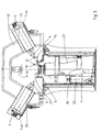
- Fig. 3 is a diagrammatic cross-sectional view of a second embodiment of the apparatus according to the invention, which shows the measuring unit is a first position thereof.
- Fig. 4 shows part of the cross-sectional view of Fig. 3 on a larger scale.
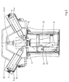
- Fig. 5 is a cross-sectional view which corresponds with Fig. 3, which shows the second measuring unit in a second position thereof.
- Fig. 6 shows part of the cross-sectional view of Fig. 5 on a larger scale.
- Fig. 7 is a plan view of the part of the apparatus shown in Figs. 4 and 6, wherein the measuring unit and the tools are shown in different positions thereof.
- Fig. 8 is a simplified block diagram of the control unit of the apparatus of Figs. 1 and 3.
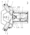
- Fig. 9 is a cross-sectional view corresponding with Fig. 3 of the apparatus according to the invention, wherein a forming tool is mounted on the carrier of the drive means, and wherein an alternative measuring unit is mounted on said forming tool.
- Fig. 1 is a plan view of a forming machine which comprises a machine bed 1, a drive unit 2 for rotating a workpiece (not shown) about an axis of rotation 3, a forming roller 4 for working the workpiece, and means 5, 6 for moving forming roller 4 in an x-direction and a y-direction with respect to drive unit 2.
- Said moving means 5, 6 comprises a bedslide 5, which is capable of movement in x-direction, and a top slide 6, which is capable of movement in y-direction on said bedslide 5 and which supports forming roller 4.
- the x and y-directions or axes extend perpendicularly to each other in this embodiment, but this is not necessary.
- the forming machine that has been discussed so far is known per se, it is described in the applicant's EP-A-0 125 720, and the construction and operation of this machine will not be discussed in detail herein. For a more detailed explanation reference is made to EP-A-0 125 720.
- Drive unit 2 is provided with a rotary carrier 9, on which a forming tool is mounted during normal operation, on which the workpiece, which for example consists of a metal sheet, which may or may not be preformed, is transformed.
- a forming tool which for example consists of a metal sheet, which may or may not be preformed, is transformed.
- Fig. 9 shows an embodiment of the apparatus with a forming tool being mounted on carrier 9. This embodiment will be discussed in more detail hereafter.
- control unit 7 will then control moving means 5, 6, in such a manner that the workpiece is transformed as a result of forming roller 4 following one or more paths on the forming tool.
- the control programme required for this operation is stored in memory 8 in a teaching or programming phase.
- said control programme comprises the x and y-positions of forming roller 4, on the basis of which moving means 5, 6 are controlled by control unit 7. It will be apparent that by controlling the moving means 5, 6 along the indicated x and y-axes, forming roller 4 can be moved along any desired path along axis of rotation 3.
- a similar drawback occurs with the known forming machine when forming roller 4 is to be exchanged or worked, since the contour and/or the position of said contour with respect to axis of rotation 3 will no longer correspond with the contour and/or the position stored during the teaching or programming phase.
- the aforesaid angle and contour and/or position are in fact apparatus parameters which influence the control programme.
- control unit 7 With the forming machine according to the invention the existing control programme may be maintained, in spite of the fact that the apparatus parameter(s) has (have) changed, since control unit 7 is arranged for measuring one or more of these parameters.
- the parameter(s) is (are) stored at the control programme in memory 8 during the teaching or programming phase. In the event of parameters being changed by maintenance work or by another cause, said parameters will be measured anew and be compared with the parameters that are stored in the memory. If there appears to be a difference between a recorded parameter and the measured value, control unit 7 will adapt the control programme in question, in such a manner that forming roller 4 will follow the desired paths all the same.
- the forming machine comprises a measuring unit 11, by means of which the control unit 7 can measure the angle between axis of rotation 3 and the y-direction.
- measuring unit 11 includes two measuring elements 12, which each comprise a laser diode 13 and a receiver 14.
- Measuring unit 11 comprises a mounting unit 15, which is fixed to carrier 9 and which has two U-shaped supporting arms 16, 17, which each support a diode-receiver pair 13, 14.
- Mounting unit 15 furthermore comprises an adjusting arm 18, which is supported on machine bed 1 with an adjusting element 19, whereby adjusting element 19 is adjusted such that the light beam of diode 13 extends exactly perpendicularly to the plane in which axis of rotation 3 and the y-axis lie.
- control unit 7 will control moving means 5, 6 in such a manner that the circumference of the forming roller 4 which is used in this example will be scanned carefully by measuring element 12 of the first U-shaped arm 16, whereby the control unit will store the x and y-positions of moving means 5, 6 that are associated with one or more predetermined points on said circumference, preferably the highest point or several points of forming roller 4. Then the control unit will move forming roller 4 to measuring element 12 of second U-shaped arm 17, which position is schematically illustrated in Fig. 1.
- Control unit 7 will then control moving means 5, 6 again, so that the measuring element in question of arm 17 will scan the circumference of forming roller 4 and store the x and y-positions of the same point or points. Since the control unit 7 will establish the movement of moving means 5, 6 in a usual manner, by means of measuring elements 20, 21, the control unit can simply calculate the angle between the x or y-direction and axis of rotation 3 from the two different x and y-positions of the predetermined point of forming roller 4. This angle will be stored in memory 8 at the control programme which is stored in said memory 8 in the teaching or programming phase.
- control unit 7 When the forming machine is subsequently prepared for a production phase with the forming tool in question, control unit 7 will first measure the angle between axis of rotation 3 and the x or y-direction in the above-described manner, and compare said angle with the angle stored at the control programme in question. If a difference is detected between the stored angle and the measured angle, control unit 7 can adapt the x and y-positions of moving means 5, 6 to the changed angle in a simple manner, so that the stored control programme can be used in spite of a change in said angle.
- This adaptation may for example take place by converting the x and y-positions angle into orthogonal positions with respect to axis of rotation 3 on the basis of the angle that has been measured in the teaching or programming phase. Then said orthogonal positions are converted back into corrected x and y-positions for moving means 5, 6 again on the basis of the changed angle, wherein the changed angle is stored for any future corrections in case changes in the angle should occur again.
- the above-described apparatus and method also have the advantage that the control programme which has been stored in a teaching or programming phase on a first forming machine can be simply used with another forming machine having comparable settings in a particular production phase, because a control unit of this other forming machine will first measure the angle between the axis of rotation and the x or y-direction again, and if a difference is detected between the measured angle and the stored angle, the control unit can adapt the control programme to the associated forming machine.
- This is a significant advantage, since only one control programme needs to be stored in a teaching or programming phase in the case of mass production with several forming machines, after which this control programme can be used on all forming machines.
- Another advantage that is achieved thereby is the fact that the production time will be exactly the same for all forming machines.
- Fig. 3 shows a second embodiment of the apparatus according to the invention, which is described in more detail in the applicant's patent application of the same date, to which reference may be had for a more detailed description.
- a drive unit 22 can be moved in the direction of axis of rotation 3, which extends in horizontal direction in this case, by means of a hydraulic cylinder 23, whereby the movement is measured by a measuring element 24.
- the movement of drive unit 22 in the direction of axis of rotation 3 corresponds with the movement of the bedslide in the y-direction in the forming machine of Fig. 1.
- two forming rollers 4 are disposed on either side of axis of rotation 3, whereby the forming rollers are only capable of movement in y-direction by means of an associated moving means 6.
- the movement of forming rollers 4 in the x-direction is measured by measuring elements 25, 26.
- the operation of the forming machine shown in Fig. 3 corresponds with the operation of the forming machine of Fig. 1.
- a measuring unit 11 comprising two measuring elements 12 is used again, which measuring elements are disposed on U-shaped arms 16 and 17.
- the measuring unit 11 of the forming machine shown in Fig. 3 possesses another mounting unit 27, which can be mounted on rotary carrier 9 of drive unit 22.
- Fig. 3 shows drive unit 22 in a first position thereof, in which position the circumference of forming roller 4 can be scanned by means of measuring element 12 of U-shaped arm 16, all this under the control of control unit 7, which controls moving means 6, 23.
- Said scanning makes it possible to determine the x and y-positions of one or more points on the circumference of forming roller 4, preferably at least the highest point.
- drive unit 22 is moved downwards to the position shown in Fig. 5.
- the circumference of forming roller 4 can be scanned with the measuring element 12 of U-shaped arm 17.
- control unit 7 can determine the angle between the y-direction and axis of rotation 3, which coincides with the x-direction in this embodiment, and store it in the above-described manner at the control programme and/or compare it with the stored angle.
- the control programme can be adapted again, as a result of which the above-described advantages will be obtained.
- mounting unit 27 comprises two diametrically opposite adjusting arms 28, 29, which are capable of cooperation with a stop member 31, which is mounted on a frame part 30.
- Fig. 7 is a schematic plan view of the part shown in Figs. 4 and 6, wherein the forming roller present on either side of axis of rotation 3 is shown in two different positions thereof, and wherein also measuring elements 12 are shown in two different positions thereof. From this plan view it appears that the adjusting arms 28, 29 cooperate with the stop member 31 in such a manner that the light beam of diode 13 extends perpendicularly to the common plane of the axis of rotation and the x-direction. This helps to prevent measuring errors.
- a carrier beam 32 which is fixed to the frame of the forming machine in a manner which is not shown.
- Said carrier beam 32 also carries a clamping unit 10 (not shown), by means of which a workpiece to be worked can be clamped against a forming tool to be mounted on carrier 9.
- Fig. 9 shows an embodiment of the forming machine according to Figs. 3 and 5, wherein a forming tool 33 is mounted on carrier 9 of drive unit 22.
- a measuring unit 34 which comprises a measuring element 12, which, as described above, consists of a laser diode and a receiver, which are carried by a U-shaped arm 16.
- Two adjusting arms 28 are disposed in diametrically opposite relationship in the same manner as with measuring unit 11, which adjusting arms are capable of cooperation with the stop member 31 mounted on frame part 30. This makes it possible to lock measuring unit 34 in a measuring position for measuring the contour and the position of forming rollers 4 shown on the right and on the left in the sectional view according to Fig. 9.
- Control unit 7 can move forming roller 4 and drive unit 22 with respect to each other by controlling hydraulic cylinder and the respective moving means 6, in such a manner that measuring element 12 of measuring unit 34 will scan the contour of forming roller 4, which contour is stored in memory 8 in the form of x and y-positions.
- the x and y-position(s) that have been stored by means of measuring unit 34 may be considered as zero point(s) for the teaching or programming phase.
- measuring unit 34 is first mounted on forming tool 33 again before the control programme is executed in the production phase, after which the contour of forming roller 4 is scanned again.
- the x and y-position obtained thereby which may be considered as zero point(s) for the reproduction phase, are compared by control unit 7 with the x and y-positions which are stored in memory 8, and if differences are detected, control unit 7 will adapt the control programme, so that the correct path/paths will be travelled by the forming roller in spite of changes in the contour and/or the position of forming roller 4 or in the position of the front surface of forming tool 33.
- This adaptation can be achieved in a simple manner in this case, for example by correcting the x and y-positions of moving means 5, 6 for each point of the path/paths stored in the memory in dependence on the differences that have been measured.
- the forming machine according to Figs. 3 and 9 may also comprise more than two forming rollers, whereby the measuring unit may have one adjusting arm for each forming roller.
- the measuring unit may have one adjusting arm for each forming roller.
- the invention has been explained by means of a forming machine in the above, the invention may also be used with other types of apparatus for working a workpiece, for example with a lathe. It is noted that it is also possible to use other types of measuring elements than the above-described measuring elements 12 comprising a laser diode and a receiver, for example mechanical, electronic, electromagnetic, photographic or optical measuring means, or measuring means that operate acoustically or pneumatically.
Abstract
Description
- The invention relates to an apparatus for working a workpiece, which apparatus comprises drive means for rotating a carrier about an axis of rotation, a tool for working said workpiece, means for moving said tool in an x-direction and a y-direction with respect to said drive means, and a control unit comprising a memory for one or more control programmes, wherein said control unit is arranged for controlling said moving means in accordance with a control programme, in such a manner that said tool follows one or more desired paths for working the workpiece, and also to a method for storing a control programme for such an apparatus and to a method for controlling such an apparatus.
- Apparatus of the above kind are known in various embodiments thereof, and they may be adapted for working the workpiece, whether or not by removing stock. Known apparatus are for example lathes, forming lathes or the like. Usually a control programme is stored in the memory in a teaching or programming phase in the known apparatus, after which the control unit controls the moving means in accordance with the control programme in the production phase, so that the tool is moved in the desired path or paths along the workpiece, which is clamped in the apparatus, so as to carry out the desired working step on the workpiece. One problem that occurs with known apparatus is that when the tool is exchanged or worked, the tool contour and/or the position of said contour with respect to the axis of rotation no longer correspond with the contour and/or the position of the tool during the teaching or programming phase, in particular if the tool must be adjusted in advance outside the apparatus. Another problem is that when maintenance or repairs are being carried out on the apparatus, whereby the moving means are for example detached from the frame of the apparatus, it is virtually impossible to fix the moving means in exactly the same position in the apparatus again. In such cases a change actually occurs in one or more apparatus parameters that influence the control programme, as a result of which the stored programme can no longer be used. In that case it will be necessary to store the control programme for the product in question in the memory anew in a teaching or programming phase.
- In the mass production of large numbers of identical products, several apparatus of the above kind will usually produce the same workpiece. With the known apparatus a control programme must be stored in the memory in a teaching or programming phase for each apparatus separately. This makes it virtually impossible to achieve an exactly synchronized same production time for all apparatus which produce the same product. This is a drawback, in particular if the worked workpieces from two or more apparatus must subsequently undergo further working in a common subsequent apparatus.
- The object of the invention is to provide an apparatus of the kind referred to in the introduction, wherein the above drawbacks have been overcome in a simple and efficient manner.
- In order to accomplish that objective the apparatus according to the invention is characterized by the characterizing portion of
claim 1. - The invention is based on the insight that by storing the apparatus parameters, such as the angle between the axis of rotation and one of the directions of movement, and preferably also the tool contour and the position of said contour with respect to the axis of rotation, in the control programme, said control programme is in fact made independent of said parameters. By having the control unit measure these parameters before a workpiece is worked in accordance with a control programme, the control unit can establish the difference between the values stored at the control programme in question and the measured values, and, if a difference is detected, adapt the control programme so that the tool will follow the desired path or paths in spite of any such deviation. This means that a new teaching or programming phase for continuing the production in accordance with an already stored control programme is no longer necessary when the tool is exchanged or worked. In addition, a control programme which has been stored in a particular apparatus in a teaching or programming phase together with the associated apparatus parameter(s), can be used in other apparatus without any problem, whereby said control programme can be adapted to the apparatus in question in a simple manner by having the control unit measure the apparatus parameter(s). All apparatus will then have the same production time. Moreover, a teaching or programming phase is only required for one apparatus, after which the control programme can be used for all other apparatus which are used for producing the same product.
- Another advantage of the apparatus according to the invention is furthermore the fact that a user of the apparatus can order a control programme for the manufacture of a particular product from the manufacturer or from another supplier, which programme can be stored in a teaching or programming phase on an available machine by the supplier, and subsequently be made available to the user.
- Consequently the invention also provides a method for storing a control programme for an apparatus for working a workpiece, which apparatus comprises drive means for rotating a carrier about an axis of rotation, a tool for working the workpiece, means for moving said tool with respect to said drive means in an x-direction and a y-direction, and a control unit comprising a memory for one or more control programmes, wherein a working step is carried out on the workpiece in a teaching or programming phase, and one or more paths followed by the tool during the working of the workpiece are stored in the memory in the form of a control programme for said moving means, characterized by the characterising portion of
claim 13. - The invention furthermore provides a method for controlling an apparatus for working a workpiece, which apparatus comprises drive means for rotating a carrier about an axis of rotation, a tool for working the workpiece, means for moving said tool with respect to said drive means in an x-direction and a y-direction, and a control unit comprising a memory for storing one or more control programmes and at least one apparatus parameter, wherein said control unit is arranged for controlling said moving means in accordance with a control programme, in such a manner that said tool follows one or more desired paths for working the workpiece, characterized by the characterising portion of
claim 15. - For the sake of completeness, it is noted that US 5,387,061 discloses a compensation system for a computer-controlled machining apparatus which alters the pre-programmed path of a cutting tool if the actual contour of a workpiece differs from an expected contour.
- The invention will be explained in more detail hereafter with reference to the drawing, which diagrammatically shows a few embodiments of the apparatus according to the invention.
- Fig. 1 is a plan view of a first embodiment of the apparatus according to the invention.
- Fig. 2 is a very diagrammatic, larger-scale front view of a part of the apparatus of Fig. 1.
- Fig. 3 is a diagrammatic cross-sectional view of a second embodiment of the apparatus according to the invention, which shows the measuring unit is a first position thereof.
- Fig. 4 shows part of the cross-sectional view of Fig. 3 on a larger scale.
- Fig. 5 is a cross-sectional view which corresponds with Fig. 3, which shows the second measuring unit in a second position thereof.
- Fig. 6 shows part of the cross-sectional view of Fig. 5 on a larger scale.
- Fig. 7 is a plan view of the part of the apparatus shown in Figs. 4 and 6, wherein the measuring unit and the tools are shown in different positions thereof.
- Fig. 8 is a simplified block diagram of the control unit of the apparatus of Figs. 1 and 3.
- Fig. 9 is a cross-sectional view corresponding with Fig. 3 of the apparatus according to the invention, wherein a forming tool is mounted on the carrier of the drive means, and wherein an alternative measuring unit is mounted on said forming tool.
- Fig. 1 is a plan view of a forming machine which comprises a
machine bed 1, adrive unit 2 for rotating a workpiece (not shown) about an axis ofrotation 3, a formingroller 4 for working the workpiece, and means 5, 6 for moving formingroller 4 in an x-direction and a y-direction with respect todrive unit 2. Said moving means 5, 6 comprises abedslide 5, which is capable of movement in x-direction, and atop slide 6, which is capable of movement in y-direction on saidbedslide 5 and which supports formingroller 4. The x and y-directions or axes extend perpendicularly to each other in this embodiment, but this is not necessary. - A
control unit 7, which is shown in a strongly simplified block diagram in Fig. 8, is arranged for controllingmoving means memory 8, in such a manner that formingroller 4 follows one or more desired paths for transforming the workpiece into the desired product or semi-finished product. The forming machine that has been discussed so far is known per se, it is described in the applicant's EP-A-0 125 720, and the construction and operation of this machine will not be discussed in detail herein. For a more detailed explanation reference is made to EP-A-0 125 720. -
Drive unit 2 is provided with arotary carrier 9, on which a forming tool is mounted during normal operation, on which the workpiece, which for example consists of a metal sheet, which may or may not be preformed, is transformed. Reference is made to Fig. 9, which shows an embodiment of the apparatus with a forming tool being mounted oncarrier 9. This embodiment will be discussed in more detail hereafter. - The workpiece is clamped against the forming tool mounted on
carrier 9 by means of achuck unit 10, in order to be transformed.Control unit 7 will then control moving means 5, 6, in such a manner that the workpiece is transformed as a result of formingroller 4 following one or more paths on the forming tool. The control programme required for this operation is stored inmemory 8 in a teaching or programming phase. Among other things said control programme comprises the x and y-positions of formingroller 4, on the basis of which moving means 5, 6 are controlled bycontrol unit 7. It will be apparent that by controlling the movingmeans roller 4 can be moved along any desired path along axis ofrotation 3. - When moving means 5, 6 must be removed from
machine bed 1, for example for maintenance or repairs, is virtually impossible in practice to mount moving means 5, 6 ontomachine bed 1 again in such a manner that the x or y-direction will include exactly the same angle with axis ofrotation 3 again. The consequence of a deviation of this angle from the angle at which the control programme was stored in the teaching or programming phase, however, is that formingroller 4 will no longer follow the desired paths if the same control programme is maintained. With the known forming machine the control programme must be stored anew in a teaching or programming phase. - A similar drawback occurs with the known forming machine when forming
roller 4 is to be exchanged or worked, since the contour and/or the position of said contour with respect to axis ofrotation 3 will no longer correspond with the contour and/or the position stored during the teaching or programming phase. The aforesaid angle and contour and/or position are in fact apparatus parameters which influence the control programme. - With the forming machine according to the invention the existing control programme may be maintained, in spite of the fact that the apparatus parameter(s) has (have) changed, since
control unit 7 is arranged for measuring one or more of these parameters. The parameter(s) is (are) stored at the control programme inmemory 8 during the teaching or programming phase. In the event of parameters being changed by maintenance work or by another cause, said parameters will be measured anew and be compared with the parameters that are stored in the memory. If there appears to be a difference between a recorded parameter and the measured value,control unit 7 will adapt the control programme in question, in such a manner that formingroller 4 will follow the desired paths all the same. - In the above-described embodiment the forming machine comprises a
measuring unit 11, by means of which thecontrol unit 7 can measure the angle between axis ofrotation 3 and the y-direction. In the illustratedembodiment measuring unit 11 includes twomeasuring elements 12, which each comprise alaser diode 13 and areceiver 14.Measuring unit 11 comprises amounting unit 15, which is fixed tocarrier 9 and which has twoU-shaped supporting arms receiver pair Mounting unit 15 furthermore comprises an adjustingarm 18, which is supported onmachine bed 1 with an adjustingelement 19, whereby adjustingelement 19 is adjusted such that the light beam ofdiode 13 extends exactly perpendicularly to the plane in which axis ofrotation 3 and the y-axis lie. - If adjusting
element 19 of measuringunit 11 is correctly adjusted, thecontrol unit 7 will control moving means 5, 6 in such a manner that the circumference of the formingroller 4 which is used in this example will be scanned carefully by measuringelement 12 of thefirst U-shaped arm 16, whereby the control unit will store the x and y-positions of movingmeans roller 4. Then the control unit will move formingroller 4 to measuringelement 12 ofsecond U-shaped arm 17, which position is schematically illustrated in Fig. 1.Control unit 7 will then control moving means 5, 6 again, so that the measuring element in question ofarm 17 will scan the circumference of formingroller 4 and store the x and y-positions of the same point or points. Since thecontrol unit 7 will establish the movement of moving means 5, 6 in a usual manner, by means of measuringelements 20, 21, the control unit can simply calculate the angle between the x or y-direction and axis ofrotation 3 from the two different x and y-positions of the predetermined point of formingroller 4. This angle will be stored inmemory 8 at the control programme which is stored in saidmemory 8 in the teaching or programming phase. - When the forming machine is subsequently prepared for a production phase with the forming tool in question,
control unit 7 will first measure the angle between axis ofrotation 3 and the x or y-direction in the above-described manner, and compare said angle with the angle stored at the control programme in question. If a difference is detected between the stored angle and the measured angle,control unit 7 can adapt the x and y-positions of movingmeans - This adaptation may for example take place by converting the x and y-positions angle into orthogonal positions with respect to axis of
rotation 3 on the basis of the angle that has been measured in the teaching or programming phase. Then said orthogonal positions are converted back into corrected x and y-positions for movingmeans - The above-described apparatus and method also have the advantage that the control programme which has been stored in a teaching or programming phase on a first forming machine can be simply used with another forming machine having comparable settings in a particular production phase, because a control unit of this other forming machine will first measure the angle between the axis of rotation and the x or y-direction again, and if a difference is detected between the measured angle and the stored angle, the control unit can adapt the control programme to the associated forming machine. This is a significant advantage, since only one control programme needs to be stored in a teaching or programming phase in the case of mass production with several forming machines, after which this control programme can be used on all forming machines. Another advantage that is achieved thereby is the fact that the production time will be exactly the same for all forming machines.
- Finally the above-described method and apparatus have the advantage that a supplier can make a control programme and make this programme and a forming tool available to customers.
- Although only one forming tool is used in the above-described forming machine according to Fig. 1, it is also possible, for example, to use the invention with other types of forming machines, wherein moving
means rotation 3. - Fig. 3 shows a second embodiment of the apparatus according to the invention, which is described in more detail in the applicant's patent application of the same date, to which reference may be had for a more detailed description. In said forming machine a
drive unit 22 can be moved in the direction of axis ofrotation 3, which extends in horizontal direction in this case, by means of ahydraulic cylinder 23, whereby the movement is measured by a measuringelement 24. The movement ofdrive unit 22 in the direction of axis ofrotation 3 corresponds with the movement of the bedslide in the y-direction in the forming machine of Fig. 1. In this case two formingrollers 4 are disposed on either side of axis ofrotation 3, whereby the forming rollers are only capable of movement in y-direction by means of an associated movingmeans 6. The movement of formingrollers 4 in the x-direction is measured by measuringelements - The operation of the forming machine shown in Fig. 3 corresponds with the operation of the forming machine of Fig. 1. With the forming machine according to Fig. 3 a measuring
unit 11 comprising two measuringelements 12 is used again, which measuring elements are disposed onU-shaped arms unit 11 of the forming machine shown in Fig. 3 possesses another mountingunit 27, which can be mounted onrotary carrier 9 ofdrive unit 22. Fig. 3 shows driveunit 22 in a first position thereof, in which position the circumference of formingroller 4 can be scanned by means of measuringelement 12 ofU-shaped arm 16, all this under the control ofcontrol unit 7, which controls movingmeans roller 4, preferably at least the highest point. Then driveunit 22 is moved downwards to the position shown in Fig. 5. In this position the circumference of formingroller 4 can be scanned with the measuringelement 12 ofU-shaped arm 17. In this position ofdrive unit 22 the x and y-positions of the same point on formingroller 4 are determined. On the basis of the movement in the x and y-directions,control unit 7 can determine the angle between the y-direction and axis ofrotation 3, which coincides with the x-direction in this embodiment, and store it in the above-described manner at the control programme and/or compare it with the stored angle. In case of a difference the control programme can be adapted again, as a result of which the above-described advantages will be obtained. - As shown in the larger-scale partial sections shown in Figs. 4 and 6, mounting
unit 27 comprises two diametrically opposite adjustingarms stop member 31, which is mounted on aframe part 30. Fig. 7 is a schematic plan view of the part shown in Figs. 4 and 6, wherein the forming roller present on either side of axis ofrotation 3 is shown in two different positions thereof, and wherein also measuringelements 12 are shown in two different positions thereof. From this plan view it appears that the adjustingarms stop member 31 in such a manner that the light beam ofdiode 13 extends perpendicularly to the common plane of the axis of rotation and the x-direction. This helps to prevent measuring errors. - From Figs. 3 and 5 it appears that the moving means 6 of the two forming
rollers 4 are mounted on acarrier beam 32, which is fixed to the frame of the forming machine in a manner which is not shown.Said carrier beam 32 also carries a clamping unit 10 (not shown), by means of which a workpiece to be worked can be clamped against a forming tool to be mounted oncarrier 9. - Fig. 9 shows an embodiment of the forming machine according to Figs. 3 and 5, wherein a forming
tool 33 is mounted oncarrier 9 ofdrive unit 22. Mounted on said formingtool 33 is a measuringunit 34, which comprises a measuringelement 12, which, as described above, consists of a laser diode and a receiver, which are carried by aU-shaped arm 16. Two adjustingarms 28 are disposed in diametrically opposite relationship in the same manner as with measuringunit 11, which adjusting arms are capable of cooperation with thestop member 31 mounted onframe part 30. This makes it possible to lock measuringunit 34 in a measuring position for measuring the contour and the position of formingrollers 4 shown on the right and on the left in the sectional view according to Fig. 9. In both measuring positions the light beam of the laser diode extends perpendicularly to the common plane of axis ofrotation 3 and the y-axis.Control unit 7 can move formingroller 4 and driveunit 22 with respect to each other by controlling hydraulic cylinder and the respective moving means 6, in such a manner that measuringelement 12 of measuringunit 34 will scan the contour of formingroller 4, which contour is stored inmemory 8 in the form of x and y-positions. The x and y-position(s) that have been stored by means of measuringunit 34 may be considered as zero point(s) for the teaching or programming phase. - When forming
roller 4 is exchanged and/or worked or when formingtool 33 is exchanged after one or more control programmes have been stored, measuringunit 34 is first mounted on formingtool 33 again before the control programme is executed in the production phase, after which the contour of formingroller 4 is scanned again. The x and y-position obtained thereby, which may be considered as zero point(s) for the reproduction phase, are compared bycontrol unit 7 with the x and y-positions which are stored inmemory 8, and if differences are detected,control unit 7 will adapt the control programme, so that the correct path/paths will be travelled by the forming roller in spite of changes in the contour and/or the position of formingroller 4 or in the position of the front surface of formingtool 33. This adaptation can be achieved in a simple manner in this case, for example by correcting the x and y-positions of movingmeans - It is noted that the forming machine according to Figs. 3 and 9 may also comprise more than two forming rollers, whereby the measuring unit may have one adjusting arm for each forming roller. Of course it is also possible to use only one arm, and to provide a
stop member 31 at several positions round the axis of rotation. - Although the invention has been explained by means of a forming machine in the above, the invention may also be used with other types of apparatus for working a workpiece, for example with a lathe. It is noted that it is also possible to use other types of measuring elements than the above-described
measuring elements 12 comprising a laser diode and a receiver, for example mechanical, electronic, electromagnetic, photographic or optical measuring means, or measuring means that operate acoustically or pneumatically.
Claims (16)
- An apparatus for working a workpiece, which apparatus comprises drive means (2, 22) for rotating a carrier (9) about an axis of rotation (3), a tool (4) for working said workpiece, means (5, 6, 23) for moving said tool (4) in an x-direction and a y-direction with respect to said drive means (2, 22), and a control unit (7) comprising a memory (8) for one or more control programmes, wherein said control unit (7) is arranged for controlling said moving means (5, 6, 23) in accordance with a control programme, in such a manner that said tool (4) will follow one or more desired paths for working the workpiece, characterized in that the control unit (7) is arranged for measuring at least the angle between the axis of rotation (3) and one of the moving means (5, 6) of the apparatus as an apparatus parameter, which apparatus parameter is stored at the (each) control programme, wherein the control unit (7) is arranged for comparing the stored apparatus parameter with the measured apparatus parameter, and wherein the control unit (7), if a difference is detected between the stored apparatus parameter(s) and the measured one(s), adapts the (each) control programme in such a manner that the tool (4) will follow the desired path(s).
- An apparatus according to claim 1, which apparatus comprises a measuring unit (11) for measuring at least one predetermined point on the circumference of the tool (4) in a first and a second position with respect to the axis of rotation, wherein the control unit (7) controls the moving means (5, 6, 23) for moving the tool (4) with said predetermined point to said first and said second position, wherein the control unit (7) determines the distance which the tool (4) travels in the x and the y-directions, and wherein the control unit (7) determines said angle between the axis of rotation and one of the moving means (5, 6, 23) on the basis of said distance.
- An apparatus according to claim 1 or 2, wherein the measuring unit (11) comprises a first and a second measuring element (12) for measuring at least said predetermined point in the first and the second position.
- An apparatus according to claim 1, 2 or 3, wherein the measuring unit (11) can be coupled to the carrier of the drive means (2).
- An apparatus according to any one of the preceding claims, wherein the control unit (7) is arranged for measuring the tool contour and the position of said contour with respect to the axis of rotation (3) as apparatus parameters.
- An apparatus according to claim 5, wherein said measuring unit (11) can be coupled to the drive means carrier, wherein the control unit (7) controls the moving means (5, 6, 23) so that a measuring element (12) of the measuring unit (11) will scan the tool contour, wherein the control unit (7) determines the associated x and y-positions and compares them with the x and y-positions that are stored in the memory (8).
- An apparatus according to any one of the claims 2-6, wherein said measuring unit (11) comprises adjusting means (18, 19, 20, 29) for adjusting a measuring position of the measuring unit (11) with respect to a common plane of the axis of rotation (3) and one of the directions of movement.
- An apparatus according to claim 7, wherein said adjusting means (18, 19) comprise an adjusting arm (18), which cooperates with a machine bed.
- An apparatus according to any one of the claims 2-7, wherein two or more tools (4) or working the workpiece and moving means (5, 6, 23) for each tool (4) are provided, wherein said adjusting means (18, 19) comprise an adjusting arm (18) for each tool (4), which cooperates with a stop member (31) mounted on a frame part (30) of the apparatus, or wherein a stop member (31) is mounted on said frame part (30) for each tool (4), which stop member (31) is capable of cooperation with an adjusting arm (18) of said adjusting means (18, 19).
- An apparatus according to any one of the claims 7-9, wherein each measuring element (12) is fitted with a laser diode and a receiver, wherein the light beam of the laser diode extends perpendicularly to said common plane in the measuring position.
- An apparatus according to any one of the preceding claims, wherein the apparatus is a forming machine.
- An apparatus according to claim 11, wherein a forming tool (4) is fixed on the drive means carrier, wherein said measuring unit (11) can be mounted on said forming tool (4).
- A method for preparing a control programme for an apparatus for working a workpiece, which apparatus comprises drive means (2, 22) for rotating a carrier (9) about an axis of rotation (3), a tool (4) for working the workpiece, means for moving (5, 6, 23) said tool (4) with respect to said drive means (2, 22) in an x-direction and a y-direction, and a control unit (7) comprising a memory (8) for one or more control programmes, wherein a working step is carried out on the workpiece in a teaching or programming phase, and one or more paths followed by the tool (4) during the working of the workpiece are stored in the memory (8) in the form of a control programme for said moving means (5, 6, 23) characterized in that at least the angle between the axis of rotation (3) and one of the directions of movement of the tool is measured and stored in the memory (8).
- Method according to claim 13, wherein the tool contour and the position of said contour with respect to the axis of rotation (3) is measured and stored in the memory (8).
- A method for controlling an apparatus for working a workpiece, which apparatus comprises drive means for rotating a carrier about an axis of rotation, a tool for working the workpiece, means for moving said tool with respect to said drive means in an x-direction and a y-direction, and a control unit comprising a memory for storing one or more control programmes and at least one apparatus parameter, wherein said control unit is arranged for controlling said moving means in accordance with a control programme, in such a manner that said tool will follow one or more desired paths for working the workpiece, characterized in that at least one apparatus parameter is measured and compared with the stored apparatus parameter, and if a difference is detected between the stored apparatus parameter and the measured one, the (each) control rogramme is adapted in such a manner that the tool will follow the desired path(s), wherein the angle between the axis of rotation and one of the directions of movement of the tool is used as a apparatus parameters.
- Method according to claim 15, wherein the tool contour and the position of said contour with respect to the axis of rotation (3) is used as an apparatus parameter.
Applications Claiming Priority (2)
| Application Number | Priority Date | Filing Date | Title |
|---|---|---|---|
| NL1005318A NL1005318C2 (en) | 1997-02-20 | 1997-02-20 | Device for machining a workpiece, as well as methods for use with such a device. |
| NL1005318 | 1997-02-20 |
Publications (2)
| Publication Number | Publication Date |
|---|---|
| EP0860760A1 EP0860760A1 (en) | 1998-08-26 |
| EP0860760B1 true EP0860760B1 (en) | 2001-11-21 |
Family
ID=19764453
Family Applications (1)
| Application Number | Title | Priority Date | Filing Date |
|---|---|---|---|
| EP98200428A Expired - Lifetime EP0860760B1 (en) | 1997-02-20 | 1998-02-12 | Apparatus for working a workpiece, as well as methods to be used with such an apparatus |
Country Status (9)
| Country | Link |
|---|---|
| US (1) | US6195595B1 (en) |
| EP (1) | EP0860760B1 (en) |
| AT (1) | ATE209371T1 (en) |
| CA (1) | CA2229897C (en) |
| DE (1) | DE69802576T2 (en) |
| DK (1) | DK0860760T3 (en) |
| ES (1) | ES2168720T3 (en) |
| NL (1) | NL1005318C2 (en) |
| PT (1) | PT860760E (en) |
Families Citing this family (7)
| Publication number | Priority date | Publication date | Assignee | Title |
|---|---|---|---|---|
| US6625866B2 (en) * | 1996-03-22 | 2003-09-30 | The Boeing Company | Determinant passively-located pogo machine |
| US7900352B2 (en) * | 2001-05-18 | 2011-03-08 | Hess Engineering, Inc. | Method and apparatus for manufacturing a catalytic converter |
| ES2248556T3 (en) * | 2001-05-18 | 2006-03-16 | Hess Engineering, Inc. | METHOD AND APPLIANCE FOR MANUFACTURING A CATALYTIC CONVERTER. |
| US6983632B2 (en) * | 2002-11-20 | 2006-01-10 | Hess Engineering, Inc. | Method and apparatus for spinning to a constant length |
| DE602004005591T2 (en) | 2003-05-13 | 2007-12-06 | Hess Engineering Inc., Niles | METHOD AND DEVICE FOR PRODUCING A CATALYST |
| JP2009502505A (en) * | 2005-07-19 | 2009-01-29 | ハンセン,トーマス,シー. | Tangential production equipment |
| CN105825050B (en) * | 2016-03-11 | 2018-04-06 | 四川川大智胜软件股份有限公司 | A kind of method for realizing Self propelled Antiaircraft Gun multi-axial cord consistency check |
Family Cites Families (18)
| Publication number | Priority date | Publication date | Assignee | Title |
|---|---|---|---|---|
| US3605909A (en) * | 1963-01-11 | 1971-09-20 | Jerome H Lemelson | Tooling machine having surface sensing program starting |
| DE2509586C3 (en) * | 1975-03-05 | 1980-03-27 | Gebrueder Boehringer Gmbh, 7320 Goeppingen | Device for setting a tool cutting edge on a cutting machine tool |
| NL8301678A (en) * | 1983-05-11 | 1984-12-03 | Johan Massee | FORCING MACHINE. |
| JPS60126709A (en) * | 1983-12-14 | 1985-07-06 | Fanuc Ltd | Position controlling method |
| JPS61109109A (en) * | 1984-10-31 | 1986-05-27 | Sankyo Seiki Mfg Co Ltd | Positioning method for planar multi-joint type robot |
| JPS61195407A (en) * | 1985-02-25 | 1986-08-29 | Hitachi Zosen Corp | Processing method for numerical control data |
| US4807145A (en) * | 1986-10-15 | 1989-02-21 | Topre Corporation | Method and apparatus for measuring the shape, size, etc., of a rotary tool |
| IL89484A (en) * | 1989-03-03 | 1992-08-18 | Nct Ltd Numerical Control Tech | System for automatic finishing of machined parts |
| KR920003740B1 (en) | 1989-10-24 | 1992-05-09 | 한국과학기술연구원 | Cariesian coordinates type 3 dumensional measuring apparatus |
| JPH03251378A (en) * | 1990-02-28 | 1991-11-08 | Fanuc Ltd | Calibration system for robot |
| US5387061A (en) * | 1990-12-14 | 1995-02-07 | The United States Of America As Represented By The United States Department Of Energy | Parameter monitoring compensation system and method |
| US5255199A (en) * | 1990-12-14 | 1993-10-19 | Martin Marietta Energy Systems, Inc. | Cutting tool form compensaton system and method |
| US5419222A (en) * | 1992-10-08 | 1995-05-30 | The United States Of America As Represented By The United States Department Of Energy | Method for measuring the contour of a machined part |
| US5537850A (en) * | 1992-12-18 | 1996-07-23 | Rays Engineering Co., Ltd. | Method of shaping a wheel |
| US5363185A (en) | 1992-12-23 | 1994-11-08 | The United States Of America As Represented By The Secretary Of The Air Force | Method and apparatus for identifying three-dimensional coordinates and orientation to a robot |
| US5457367A (en) * | 1993-08-06 | 1995-10-10 | Cycle Time Corporation | Tool center point calibration apparatus and method |
| NL1003403C2 (en) * | 1996-06-24 | 1998-01-07 | Johan Massee | Device for machining a workpiece. |
| NL1005319C2 (en) * | 1997-02-20 | 1998-08-24 | Johan Massee | Device for machining a workpiece. |
-
1997
- 1997-02-20 NL NL1005318A patent/NL1005318C2/en not_active IP Right Cessation
-
1998
- 1998-02-12 DK DK98200428T patent/DK0860760T3/en active
- 1998-02-12 EP EP98200428A patent/EP0860760B1/en not_active Expired - Lifetime
- 1998-02-12 DE DE69802576T patent/DE69802576T2/en not_active Expired - Lifetime
- 1998-02-12 AT AT98200428T patent/ATE209371T1/en active
- 1998-02-12 ES ES98200428T patent/ES2168720T3/en not_active Expired - Lifetime
- 1998-02-12 PT PT98200428T patent/PT860760E/en unknown
- 1998-02-18 CA CA002229897A patent/CA2229897C/en not_active Expired - Fee Related
- 1998-02-18 US US09/025,497 patent/US6195595B1/en not_active Expired - Lifetime
Also Published As
| Publication number | Publication date |
|---|---|
| EP0860760A1 (en) | 1998-08-26 |
| DE69802576D1 (en) | 2002-01-03 |
| CA2229897A1 (en) | 1998-08-20 |
| PT860760E (en) | 2002-05-31 |
| DE69802576T2 (en) | 2002-08-01 |
| NL1005318C2 (en) | 1998-08-24 |
| US6195595B1 (en) | 2001-02-27 |
| CA2229897C (en) | 2006-07-25 |
| ATE209371T1 (en) | 2001-12-15 |
| ES2168720T3 (en) | 2002-06-16 |
| DK0860760T3 (en) | 2002-03-11 |
Similar Documents
| Publication | Publication Date | Title |
|---|---|---|
| EP0816958B1 (en) | Apparatus for machining a workpiece | |
| US6593541B1 (en) | Method for machining workpieces and machine tool | |
| US5095788A (en) | Method for compensating thermally induced displacement in machine tools | |
| US5088181A (en) | Sheet metal part machining system | |
| US5399049A (en) | V-shaped groove forming machine and its control method | |
| CA2045600A1 (en) | Dynamic correction of servo following errors in a computer-numerically-controlled system and fixed cycle utilizing same | |
| US5689988A (en) | CNC-controlled pipe bending machine | |
| GB2056897A (en) | Machine tool with laser cutting device | |
| EP0341968B1 (en) | Numerically controlled machine tool | |
| EP0860760B1 (en) | Apparatus for working a workpiece, as well as methods to be used with such an apparatus | |
| US6745101B2 (en) | Deflection compensation for numerical controlled manufacturing | |
| JP7268158B2 (en) | A pipe processing machine that cuts pipes or moldings with a laser beam | |
| JPH10133728A (en) | Automatic feedback device for product inspection data, and automatic program correcting method using the same device | |
| CN108170095B (en) | Machining method of full closed-loop system of numerical control machine tool based on vision | |
| JP2000504867A (en) | Improved monitoring system for workpiece and tool carriage movement | |
| CN114918526A (en) | Numerical control machine tool welding track correction system and method based on line laser scanning | |
| US7011122B2 (en) | Edge-routing unit for a program-controlled feed-through machine | |
| WO1999010785A1 (en) | An improved clamping device and method of operation for a cnc machine | |
| US5435360A (en) | Method for positioning a machine element having a reference point relative to a reference point provided at an abutment | |
| JP7097254B2 (en) | Workpiece movement positioning device | |
| CN107991990B (en) | Vision-based full-closed loop system of numerical control machine tool | |
| US5934213A (en) | Process for accurately determining the zero point of the needle of the sewing machine of an automatic sewing unit | |
| JP3730313B2 (en) | Processing method by bending machine and bending machine using the method | |
| EP0618520A1 (en) | A gear cutting machine | |
| CN216398499U (en) | Automatic welding gun centering device and system applying same |
Legal Events
| Date | Code | Title | Description |
|---|---|---|---|
| PUAI | Public reference made under article 153(3) epc to a published international application that has entered the european phase |
Free format text: ORIGINAL CODE: 0009012 |
|
| AK | Designated contracting states |
Kind code of ref document: A1 Designated state(s): AT BE CH DE DK ES FI FR GB IE IT LI LU NL PT SE |
|
| AX | Request for extension of the european patent |
Free format text: AL;LT;LV;MK;RO;SI |
|
| 17P | Request for examination filed |
Effective date: 19981116 |
|
| AKX | Designation fees paid |
Free format text: AT BE CH DE DK ES FI FR GB GR IE IT LI LU MC NL |
|
| AXX | Extension fees paid |
Free format text: LT PAYMENT 19981116;LV PAYMENT 19981116;RO PAYMENT 19981116;SI PAYMENT 19981116 |
|
| RBV | Designated contracting states (corrected) |
Designated state(s): AT BE CH DE DK ES FI FR GB GR IE IT LI LU MC NL |
|
| RBV | Designated contracting states (corrected) |
Designated state(s): AT BE CH DE DK ES FI FR GB IE IT LI LU NL PT SE |
|
| 17Q | First examination report despatched |
Effective date: 20000113 |
|
| GRAG | Despatch of communication of intention to grant |
Free format text: ORIGINAL CODE: EPIDOS AGRA |
|
| GRAG | Despatch of communication of intention to grant |
Free format text: ORIGINAL CODE: EPIDOS AGRA |
|
| GRAH | Despatch of communication of intention to grant a patent |
Free format text: ORIGINAL CODE: EPIDOS IGRA |
|
| GRAH | Despatch of communication of intention to grant a patent |
Free format text: ORIGINAL CODE: EPIDOS IGRA |
|
| GRAA | (expected) grant |
Free format text: ORIGINAL CODE: 0009210 |
|
| AK | Designated contracting states |
Kind code of ref document: B1 Designated state(s): AT BE CH DE DK ES FI FR GB IE IT LI LU NL PT SE |
|
| AX | Request for extension of the european patent |
Free format text: LT PAYMENT 19981116;LV PAYMENT 19981116;RO PAYMENT 19981116;SI PAYMENT 19981116 |
|
| LTIE | Lt: invalidation of european patent or patent extension | ||
| PG25 | Lapsed in a contracting state [announced via postgrant information from national office to epo] |
Ref country code: FI Free format text: LAPSE BECAUSE OF FAILURE TO SUBMIT A TRANSLATION OF THE DESCRIPTION OR TO PAY THE FEE WITHIN THE PRESCRIBED TIME-LIMIT Effective date: 20011121 |
|
| REF | Corresponds to: |
Ref document number: 209371 Country of ref document: AT Date of ref document: 20011215 Kind code of ref document: T |
|
| REG | Reference to a national code |
Ref country code: CH Ref legal event code: EP |
|
| REG | Reference to a national code |
Ref country code: IE Ref legal event code: FG4D |
|
| REG | Reference to a national code |
Ref country code: GB Ref legal event code: IF02 |
|
| REF | Corresponds to: |
Ref document number: 69802576 Country of ref document: DE Date of ref document: 20020103 |
|
| PG25 | Lapsed in a contracting state [announced via postgrant information from national office to epo] |
Ref country code: LU Free format text: LAPSE BECAUSE OF NON-PAYMENT OF DUE FEES Effective date: 20020212 |
|
| REG | Reference to a national code |
Ref country code: DK Ref legal event code: T3 |
|
| REG | Reference to a national code |
Ref country code: CH Ref legal event code: NV Representative=s name: OK PAT AG PATENTE MARKEN LIZENZEN |
|
| ET | Fr: translation filed | ||
| REG | Reference to a national code |
Ref country code: PT Ref legal event code: SC4A Free format text: AVAILABILITY OF NATIONAL TRANSLATION Effective date: 20020220 |
|
| REG | Reference to a national code |
Ref country code: ES Ref legal event code: FG2A Ref document number: 2168720 Country of ref document: ES Kind code of ref document: T3 |
|
| PLBE | No opposition filed within time limit |
Free format text: ORIGINAL CODE: 0009261 |
|
| STAA | Information on the status of an ep patent application or granted ep patent |
Free format text: STATUS: NO OPPOSITION FILED WITHIN TIME LIMIT |
|
| 26N | No opposition filed | ||
| PGFP | Annual fee paid to national office [announced via postgrant information from national office to epo] |
Ref country code: IT Payment date: 20120224 Year of fee payment: 15 |
|
| PGFP | Annual fee paid to national office [announced via postgrant information from national office to epo] |
Ref country code: IE Payment date: 20130226 Year of fee payment: 16 Ref country code: DK Payment date: 20130225 Year of fee payment: 16 Ref country code: CH Payment date: 20130225 Year of fee payment: 16 Ref country code: SE Payment date: 20130227 Year of fee payment: 16 Ref country code: GB Payment date: 20130227 Year of fee payment: 16 Ref country code: FR Payment date: 20130311 Year of fee payment: 16 Ref country code: DE Payment date: 20130227 Year of fee payment: 16 Ref country code: ES Payment date: 20130226 Year of fee payment: 16 |
|
| PGFP | Annual fee paid to national office [announced via postgrant information from national office to epo] |
Ref country code: NL Payment date: 20130227 Year of fee payment: 16 Ref country code: BE Payment date: 20130227 Year of fee payment: 16 |
|
| PGFP | Annual fee paid to national office [announced via postgrant information from national office to epo] |
Ref country code: AT Payment date: 20140121 Year of fee payment: 17 |
|
| PGFP | Annual fee paid to national office [announced via postgrant information from national office to epo] |
Ref country code: PT Payment date: 20140124 Year of fee payment: 17 |
|
| BERE | Be: lapsed |
Owner name: *MASSEE JOHAN Effective date: 20140228 |
|
| REG | Reference to a national code |
Ref country code: DE Ref legal event code: R119 Ref document number: 69802576 Country of ref document: DE |
|
| REG | Reference to a national code |
Ref country code: NL Ref legal event code: V1 Effective date: 20140901 |
|
| REG | Reference to a national code |
Ref country code: DK Ref legal event code: EBP Effective date: 20140228 |
|
| REG | Reference to a national code |
Ref country code: CH Ref legal event code: PL Ref country code: SE Ref legal event code: EUG |
|
| GBPC | Gb: european patent ceased through non-payment of renewal fee |
Effective date: 20140212 |
|
| PG25 | Lapsed in a contracting state [announced via postgrant information from national office to epo] |
Ref country code: NL Free format text: LAPSE BECAUSE OF NON-PAYMENT OF DUE FEES Effective date: 20140901 Ref country code: LI Free format text: LAPSE BECAUSE OF NON-PAYMENT OF DUE FEES Effective date: 20140228 Ref country code: CH Free format text: LAPSE BECAUSE OF NON-PAYMENT OF DUE FEES Effective date: 20140228 |
|
| REG | Reference to a national code |
Ref country code: FR Ref legal event code: ST Effective date: 20141031 |
|
| PG25 | Lapsed in a contracting state [announced via postgrant information from national office to epo] |
Ref country code: SE Free format text: LAPSE BECAUSE OF NON-PAYMENT OF DUE FEES Effective date: 20140213 |
|
| REG | Reference to a national code |
Ref country code: IE Ref legal event code: MM4A |
|
| REG | Reference to a national code |
Ref country code: DE Ref legal event code: R119 Ref document number: 69802576 Country of ref document: DE Effective date: 20140902 |
|
| PG25 | Lapsed in a contracting state [announced via postgrant information from national office to epo] |
Ref country code: IE Free format text: LAPSE BECAUSE OF NON-PAYMENT OF DUE FEES Effective date: 20140212 Ref country code: BE Free format text: LAPSE BECAUSE OF NON-PAYMENT OF DUE FEES Effective date: 20140228 Ref country code: DK Free format text: LAPSE BECAUSE OF NON-PAYMENT OF DUE FEES Effective date: 20140228 Ref country code: DE Free format text: LAPSE BECAUSE OF NON-PAYMENT OF DUE FEES Effective date: 20140902 Ref country code: GB Free format text: LAPSE BECAUSE OF NON-PAYMENT OF DUE FEES Effective date: 20140212 Ref country code: FR Free format text: LAPSE BECAUSE OF NON-PAYMENT OF DUE FEES Effective date: 20140228 |
|
| REG | Reference to a national code |
Ref country code: ES Ref legal event code: FD2A Effective date: 20150327 |
|
| PG25 | Lapsed in a contracting state [announced via postgrant information from national office to epo] |
Ref country code: ES Free format text: LAPSE BECAUSE OF NON-PAYMENT OF DUE FEES Effective date: 20140213 |
|
| REG | Reference to a national code |
Ref country code: PT Ref legal event code: MM4A Free format text: LAPSE DUE TO NON-PAYMENT OF FEES Effective date: 20150812 |
|
| REG | Reference to a national code |
Ref country code: AT Ref legal event code: MM01 Ref document number: 209371 Country of ref document: AT Kind code of ref document: T Effective date: 20150212 |
|
| PG25 | Lapsed in a contracting state [announced via postgrant information from national office to epo] |
Ref country code: PT Free format text: LAPSE BECAUSE OF NON-PAYMENT OF DUE FEES Effective date: 20150812 |
|
| PG25 | Lapsed in a contracting state [announced via postgrant information from national office to epo] |
Ref country code: AT Free format text: LAPSE BECAUSE OF NON-PAYMENT OF DUE FEES Effective date: 20150212 |
|
| PG25 | Lapsed in a contracting state [announced via postgrant information from national office to epo] |
Ref country code: IT Free format text: LAPSE BECAUSE OF NON-PAYMENT OF DUE FEES Effective date: 20140212 |