EP0859940B1 - Rotatable heat transfer apparatus - Google Patents
Rotatable heat transfer apparatus Download PDFInfo
- Publication number
- EP0859940B1 EP0859940B1 EP96935172A EP96935172A EP0859940B1 EP 0859940 B1 EP0859940 B1 EP 0859940B1 EP 96935172 A EP96935172 A EP 96935172A EP 96935172 A EP96935172 A EP 96935172A EP 0859940 B1 EP0859940 B1 EP 0859940B1
- Authority
- EP
- European Patent Office
- Prior art keywords
- heat transfer
- heat
- evaporator
- transfer fluid
- air
- Prior art date
- Legal status (The legal status is an assumption and is not a legal conclusion. Google has not performed a legal analysis and makes no representation as to the accuracy of the status listed.)
- Expired - Lifetime
Links
Images





Classifications
-
- F—MECHANICAL ENGINEERING; LIGHTING; HEATING; WEAPONS; BLASTING
- F28—HEAT EXCHANGE IN GENERAL
- F28C—HEAT-EXCHANGE APPARATUS, NOT PROVIDED FOR IN ANOTHER SUBCLASS, IN WHICH THE HEAT-EXCHANGE MEDIA COME INTO DIRECT CONTACT WITHOUT CHEMICAL INTERACTION
- F28C3/00—Other direct-contact heat-exchange apparatus
- F28C3/06—Other direct-contact heat-exchange apparatus the heat-exchange media being a liquid and a gas or vapour
- F28C3/08—Other direct-contact heat-exchange apparatus the heat-exchange media being a liquid and a gas or vapour with change of state, e.g. absorption, evaporation, condensation
-
- B—PERFORMING OPERATIONS; TRANSPORTING
- B01—PHYSICAL OR CHEMICAL PROCESSES OR APPARATUS IN GENERAL
- B01D—SEPARATION
- B01D3/00—Distillation or related exchange processes in which liquids are contacted with gaseous media, e.g. stripping
- B01D3/007—Energy recuperation; Heat pumps
-
- F—MECHANICAL ENGINEERING; LIGHTING; HEATING; WEAPONS; BLASTING
- F01—MACHINES OR ENGINES IN GENERAL; ENGINE PLANTS IN GENERAL; STEAM ENGINES
- F01K—STEAM ENGINE PLANTS; STEAM ACCUMULATORS; ENGINE PLANTS NOT OTHERWISE PROVIDED FOR; ENGINES USING SPECIAL WORKING FLUIDS OR CYCLES
- F01K25/00—Plants or engines characterised by use of special working fluids, not otherwise provided for; Plants operating in closed cycles and not otherwise provided for
- F01K25/08—Plants or engines characterised by use of special working fluids, not otherwise provided for; Plants operating in closed cycles and not otherwise provided for using special vapours
-
- F—MECHANICAL ENGINEERING; LIGHTING; HEATING; WEAPONS; BLASTING
- F03—MACHINES OR ENGINES FOR LIQUIDS; WIND, SPRING, OR WEIGHT MOTORS; PRODUCING MECHANICAL POWER OR A REACTIVE PROPULSIVE THRUST, NOT OTHERWISE PROVIDED FOR
- F03G—SPRING, WEIGHT, INERTIA OR LIKE MOTORS; MECHANICAL-POWER PRODUCING DEVICES OR MECHANISMS, NOT OTHERWISE PROVIDED FOR OR USING ENERGY SOURCES NOT OTHERWISE PROVIDED FOR
- F03G6/00—Devices for producing mechanical power from solar energy
- F03G6/003—Devices for producing mechanical power from solar energy having a Rankine cycle
-
- F—MECHANICAL ENGINEERING; LIGHTING; HEATING; WEAPONS; BLASTING
- F03—MACHINES OR ENGINES FOR LIQUIDS; WIND, SPRING, OR WEIGHT MOTORS; PRODUCING MECHANICAL POWER OR A REACTIVE PROPULSIVE THRUST, NOT OTHERWISE PROVIDED FOR
- F03G—SPRING, WEIGHT, INERTIA OR LIKE MOTORS; MECHANICAL-POWER PRODUCING DEVICES OR MECHANISMS, NOT OTHERWISE PROVIDED FOR OR USING ENERGY SOURCES NOT OTHERWISE PROVIDED FOR
- F03G6/00—Devices for producing mechanical power from solar energy
- F03G6/003—Devices for producing mechanical power from solar energy having a Rankine cycle
- F03G6/005—Binary cycle plants where the fluid from the solar collector heats the working fluid via a heat exchanger
-
- F—MECHANICAL ENGINEERING; LIGHTING; HEATING; WEAPONS; BLASTING
- F21—LIGHTING
- F21V—FUNCTIONAL FEATURES OR DETAILS OF LIGHTING DEVICES OR SYSTEMS THEREOF; STRUCTURAL COMBINATIONS OF LIGHTING DEVICES WITH OTHER ARTICLES, NOT OTHERWISE PROVIDED FOR
- F21V29/00—Protecting lighting devices from thermal damage; Cooling or heating arrangements specially adapted for lighting devices or systems
-
- F—MECHANICAL ENGINEERING; LIGHTING; HEATING; WEAPONS; BLASTING
- F25—REFRIGERATION OR COOLING; COMBINED HEATING AND REFRIGERATION SYSTEMS; HEAT PUMP SYSTEMS; MANUFACTURE OR STORAGE OF ICE; LIQUEFACTION SOLIDIFICATION OF GASES
- F25B—REFRIGERATION MACHINES, PLANTS OR SYSTEMS; COMBINED HEATING AND REFRIGERATION SYSTEMS; HEAT PUMP SYSTEMS
- F25B1/00—Compression machines, plants or systems with non-reversible cycle
- F25B1/06—Compression machines, plants or systems with non-reversible cycle with compressor of jet type, e.g. using liquid under pressure
-
- F—MECHANICAL ENGINEERING; LIGHTING; HEATING; WEAPONS; BLASTING
- F25—REFRIGERATION OR COOLING; COMBINED HEATING AND REFRIGERATION SYSTEMS; HEAT PUMP SYSTEMS; MANUFACTURE OR STORAGE OF ICE; LIQUEFACTION SOLIDIFICATION OF GASES
- F25B—REFRIGERATION MACHINES, PLANTS OR SYSTEMS; COMBINED HEATING AND REFRIGERATION SYSTEMS; HEAT PUMP SYSTEMS
- F25B15/00—Sorption machines, plants or systems, operating continuously, e.g. absorption type
- F25B15/02—Sorption machines, plants or systems, operating continuously, e.g. absorption type without inert gas
-
- F—MECHANICAL ENGINEERING; LIGHTING; HEATING; WEAPONS; BLASTING
- F28—HEAT EXCHANGE IN GENERAL
- F28D—HEAT-EXCHANGE APPARATUS, NOT PROVIDED FOR IN ANOTHER SUBCLASS, IN WHICH THE HEAT-EXCHANGE MEDIA DO NOT COME INTO DIRECT CONTACT
- F28D15/00—Heat-exchange apparatus with the intermediate heat-transfer medium in closed tubes passing into or through the conduit walls ; Heat-exchange apparatus employing intermediate heat-transfer medium or bodies
- F28D15/02—Heat-exchange apparatus with the intermediate heat-transfer medium in closed tubes passing into or through the conduit walls ; Heat-exchange apparatus employing intermediate heat-transfer medium or bodies in which the medium condenses and evaporates, e.g. heat pipes
-
- F—MECHANICAL ENGINEERING; LIGHTING; HEATING; WEAPONS; BLASTING
- F25—REFRIGERATION OR COOLING; COMBINED HEATING AND REFRIGERATION SYSTEMS; HEAT PUMP SYSTEMS; MANUFACTURE OR STORAGE OF ICE; LIQUEFACTION SOLIDIFICATION OF GASES
- F25B—REFRIGERATION MACHINES, PLANTS OR SYSTEMS; COMBINED HEATING AND REFRIGERATION SYSTEMS; HEAT PUMP SYSTEMS
- F25B2341/00—Details of ejectors not being used as compression device; Details of flow restrictors or expansion valves
- F25B2341/001—Ejectors not being used as compression device
- F25B2341/0011—Ejectors with the cooled primary flow at reduced or low pressure
-
- F—MECHANICAL ENGINEERING; LIGHTING; HEATING; WEAPONS; BLASTING
- F25—REFRIGERATION OR COOLING; COMBINED HEATING AND REFRIGERATION SYSTEMS; HEAT PUMP SYSTEMS; MANUFACTURE OR STORAGE OF ICE; LIQUEFACTION SOLIDIFICATION OF GASES
- F25B—REFRIGERATION MACHINES, PLANTS OR SYSTEMS; COMBINED HEATING AND REFRIGERATION SYSTEMS; HEAT PUMP SYSTEMS
- F25B9/00—Compression machines, plants or systems, in which the refrigerant is air or other gas of low boiling point
- F25B9/02—Compression machines, plants or systems, in which the refrigerant is air or other gas of low boiling point using Joule-Thompson effect; using vortex effect
- F25B9/04—Compression machines, plants or systems, in which the refrigerant is air or other gas of low boiling point using Joule-Thompson effect; using vortex effect using vortex effect
-
- Y—GENERAL TAGGING OF NEW TECHNOLOGICAL DEVELOPMENTS; GENERAL TAGGING OF CROSS-SECTIONAL TECHNOLOGIES SPANNING OVER SEVERAL SECTIONS OF THE IPC; TECHNICAL SUBJECTS COVERED BY FORMER USPC CROSS-REFERENCE ART COLLECTIONS [XRACs] AND DIGESTS
- Y02—TECHNOLOGIES OR APPLICATIONS FOR MITIGATION OR ADAPTATION AGAINST CLIMATE CHANGE
- Y02B—CLIMATE CHANGE MITIGATION TECHNOLOGIES RELATED TO BUILDINGS, e.g. HOUSING, HOUSE APPLIANCES OR RELATED END-USER APPLICATIONS
- Y02B30/00—Energy efficient heating, ventilation or air conditioning [HVAC]
- Y02B30/52—Heat recovery pumps, i.e. heat pump based systems or units able to transfer the thermal energy from one area of the premises or part of the facilities to a different one, improving the overall efficiency
-
- Y—GENERAL TAGGING OF NEW TECHNOLOGICAL DEVELOPMENTS; GENERAL TAGGING OF CROSS-SECTIONAL TECHNOLOGIES SPANNING OVER SEVERAL SECTIONS OF THE IPC; TECHNICAL SUBJECTS COVERED BY FORMER USPC CROSS-REFERENCE ART COLLECTIONS [XRACs] AND DIGESTS
- Y02—TECHNOLOGIES OR APPLICATIONS FOR MITIGATION OR ADAPTATION AGAINST CLIMATE CHANGE
- Y02E—REDUCTION OF GREENHOUSE GAS [GHG] EMISSIONS, RELATED TO ENERGY GENERATION, TRANSMISSION OR DISTRIBUTION
- Y02E10/00—Energy generation through renewable energy sources
- Y02E10/40—Solar thermal energy, e.g. solar towers
- Y02E10/46—Conversion of thermal power into mechanical power, e.g. Rankine, Stirling or solar thermal engines
-
- Y—GENERAL TAGGING OF NEW TECHNOLOGICAL DEVELOPMENTS; GENERAL TAGGING OF CROSS-SECTIONAL TECHNOLOGIES SPANNING OVER SEVERAL SECTIONS OF THE IPC; TECHNICAL SUBJECTS COVERED BY FORMER USPC CROSS-REFERENCE ART COLLECTIONS [XRACs] AND DIGESTS
- Y02—TECHNOLOGIES OR APPLICATIONS FOR MITIGATION OR ADAPTATION AGAINST CLIMATE CHANGE
- Y02P—CLIMATE CHANGE MITIGATION TECHNOLOGIES IN THE PRODUCTION OR PROCESSING OF GOODS
- Y02P70/00—Climate change mitigation technologies in the production process for final industrial or consumer products
- Y02P70/10—Greenhouse gas [GHG] capture, material saving, heat recovery or other energy efficient measures, e.g. motor control, characterised by manufacturing processes, e.g. for rolling metal or metal working
Definitions
- This invention relates to heat transfer apparatus.
- heat transfer apparatus comprising a rotatable heat exchanger (4012) comprising a rotatable shaft, the apparatus further including drive means (4022) for rotating the heat exchanger (4012), and supply means (4040) for supplying a heat transfer fluid (4036) to the rotatable heat exchanger, characterised in that the rotatable heat exchanger further includes a plurality of elongate elements (4014) extending outwardly from the rotatable shaft, each element (4014) having an outwardly extending dimension which is greater than the diameter of the shaft, whereby when the heat exchanger (4012) is rotated, heat can be transferred to or from the heat transfer fluid (4036) at said elongate elements (4014).
- the elongate elements comprise fins in the form of spines, needles or narrow strips.
- An advantage of a rotatable heat exchanger is that by using a large number of elongate elements, it provides a large surface area. For example, a heat exchanger having a diameter of 30cm can provide a surface area of 8m 2 .
- the heat transfer apparatus may be in the form of a generator for generating evaporated heat transfer fluid. In another embodiment, the heat transfer apparatus may be in the form of a condenser for receiving and condensing evaporated heat transfer fluid. In another embodiment, the heat transfer apparatus may comprise an absorber whereby an absorbent therein can absorb evaporated heat transfer fluid supplied thereto. In another embodiment, the heat transfer apparatus may comprise an evaporator to receive and evaporate expanded heat transfer fluid supplied thereto.
- the apparatus comprises a housing for the rotatable heat exchanger.
- the housing may include a reservoir to hold a liquid, and may further include collection means to collect some of said liquid and deliver the liquid to the elongate elements of the rotatable heat exchanger.
- the collection means may comprise a pipe rotatable with said rotatable heat exchanger.
- the collection means is preferably fixedly mounted on the shaft for rotation therewith.
- the collection means comprises a scoop pipe.
- the collection means may be in the form of a pump operated by the rotation of the rotatable heat exchanger.
- the rotatable shaft may comprise a conduit capable of transferring heat from one end region thereof to the opposite end region, upon which conduit the elongate elements are fixedly mounted.
- the conduit is in the form of a rotatable heat pipe. Heat may be transferred to the heat pipe from the elongate elements. Alternatively, heat may be transferred from the heat pipe to the elongate elements.
- the rotatable shaft may be a spindle upon which the elongate elements are fixedly mounted.
- a heat transfer assembly comprising a heat transfer apparatus as described above connected to at least one further heat transfer apparatus for transferring the heat transfer fluid from one region of the assembly to another thereby transferring heat from one region of the assembly to another.
- the heat transfer assembly may comprise an evaporator for evaporating expanded heat transfer fluid.
- the assembly may further include an absorber to receive said evaporated heat transfer fluid from the evaporator, the absorber containing an absorbent to absorb said heat transfer fluid, to produce a strong heat transfer fluid/absorbent solution.
- a generator may also be provided for receiving said strong solution to generate evaporated heat transfer fluid and to produce a weak heat transfer fluid/absorbent solution.
- the assembly may further include a condenser to receive and condense said evaporated heat transfer fluid from the generator.
- strong heat transfer fluid/absorbent solution is intended to mean a solution having a high concentration of heat transfer fluid.
- weak heat transfer fluid/absorbent solution is intended to refer to a solution having a low concentration of heat transfer fluid.
- At least one of the evaporator, the absorber, the generator, and the condenser preferably comprises a heat transfer apparatus described in the relevant paragraphs above.
- the weak heat transfer fluid/absorbent solution is conveniently supplied from the generator to the absorber.
- each of the evaporator, the absorber and the generator comprise a heat transfer apparatus described in the relevant paragraphs above.
- the condenser may also comprise a heat transfer apparatus as described in the relevant paragraphs above.
- These embodiments may comprise a cycle whereby the condensed heat transfer fluid is supplied from the condenser to the evaporator preferably via expansion means to expand the heat transfer fluid, thereby reducing the pressure thereof.
- the shafts of the rotatable heat exchangers of the generator and the condenser may comprise heat pipes.
- each of the evaporator and the absorber comprise a heat transfer apparatus as described in the relevant paragraphs above.
- This embodiment may comprise an open cycle whereby heat transfer fluid is evaporated away at the generator, which may be solar powered.
- the generator comprises a solar collector.
- Feed means may be provided to feed further refrigerant to the assembly.
- the evaporator, the absorber and the generator may each comprise a heat transfer apparatus as described above, wherein the assembly provides an open cycle including feed means for feeding a solution comprising the heat transfer fluid as the solvent, to the evaporator for evaporation of the heat transfer fluid therefrom, and condensate discharge means for discharging condensed heat transfer fluid from the condenser.
- the assembly of the fourth embodiment may further include solvent discharge means for discharging the concentrated solution from the evaporator.
- each of the absorber, the condenser and the generator may comprise a heat transfer apparatus as described above.
- This embodiment may comprise an open cycle for drying applications when the heat transfer fluid comprises water.
- the absorber may include an inlet for receiving humid air and an outlet for discharging dry air, the absorbent being adapted to absorb the water in the air.
- the condenser is provided with a water outlet whereby condensed water can be discharged.
- the assembly comprises two cycles connected by heat transfer means, and may be in the form of an air conditioning system.
- the first cycle of the assembly comprises an absorber to receive warm humid area to remove the moisture from said air thereby drying the air an evaporator to receive the dried air, and to receive a heat transfer fluid, advantageously water whereby, the water is evaporated to cool and humidify the incoming dry air, thereby to produce cooled moist air therefrom.
- Heat transfer means is conveniently arranged between the absorber and the evaporator to transfer heat from the first cycle to the second cycle.
- the heat transfer means is a heat pipe, one end region of which is arranged in the path between the absorber and the evaporator.
- the second cycle and evaporator for receiving warm air, and to receive a heat transfer fluid, whereby the heat transfer fluid is evaporated into the morning air to cool and humidify the air and exhaust means, to exhaust the humidified air.
- the heat transfer means is conveniently arranged between the evaporator and the exhaust means of the second cycle.
- the opposite end region of the heat transfer means is arranged in the path of the air between the evaporator and the exhaust means.
- the evaporator and the absorber of the first cycle and the evaporator of the second cycle may each comprise a heat transfer apparatus as described in the relevant paragraphs above.
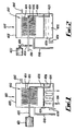
- heat transfer apparatus 4010 comprising a rotatable heat exchanger 4012 comprising a plurality of elongate elements in the form of elongate needles 4014 mounted on a shaft which, in the case of the embodiment shown in Fig. 1 is in the form of a spindle 4016, and in the case of the embodiment shown in Fig. 2, is in the form of a rotatable heat pipe 4018.
- the spindle 4016 is connected via a rod 4020 to a drive motor 4022.
- the heat pipe 4018 is connected via a pulley 4024 and a belt 4026 to the drive motor 4022.
- the elongate needles 4014 extend outwardly from the spindle 4016 or heat pipe 4018 circumferentially around the spindle 4016 or heat pipe 4018 to provide a large surface area for the transfer of heat to or from heat transfer fluid applied to the needles 4014.
- the apparatus includes collection means in the form of a scoop pipe 4028 mounted on an elongate member 4030 which, in turn, is fixedly to the shaft 4016 or heat pipe 4018, as shown.
- the apparatus 4010 comprises a housing 4032 in which the heat exchanger is housed, and the housing 4032 includes a reservoir 4034 in which a heat transfer fluid 4036 is contained.
- An outlet pipe 4038 extends from the reservoir to discharge the heat transfer fluid 4036 therefrom, and an inlet pipe 4040 is connected to the housing 4032 to supply a heat transfer fluid thereto.
- the heat transfer fluid supplied to the housing 4032 may, or may not, be the same as the heat transfer fluid 4036 discharged via the pipe 4038.
- the apparatus is functioning as an absorber, the heat transfer fluid entering the apparatus 4010 will be in the form of a refrigerant whereas the heat transfer fluid in the reservoir 4032 will be in the form of a solution of refrigerant/absorbent.
- a conduit 4042 extends from the housing 4032 in the vicinity of the needles 4014 to supply evaporated heat transfer fluid to the needles 4014, or to discharge evaporated heated transfer fluid from the housing 4032, depending upon the function of the apparatus 4010.
- heat input or removal means 4044 is provided either to heat the heat transfer fluid 4036, or remove heat therefrom depending upon the function of the apparatus 4010.
- the heat pipe 4018 comprises a first end region 4044 external of the housing 4032, and a second end region 4046 located inside the housing 4032.
- heat may be supplied to the end region 4044 to be transferred along the heat pipe to the end region 4046 thereby to evaporate heat transfer fluid on the needles 4014.
- heat can be removed from the end region 4044 thereby allowing heat to be transferred from the second end region 4046 to a region outside the housing 4032.
- the drive motor 4022 operates to rotate the heat exchanger 4012 which, in turn, rotates the scoop pipe 4028. This causes heat transfer fluid 4036 to be dispersed over the whole surface of the needles 4014, to provide efficient heat transfer.
- the apparatus shown in Figs. 1 and 2 can be in the form of a generator for generating evaporated heat transfer fluid, a condenser for condensing evaporated heat transfer fluid, an absorber holding an absorbent for absorbing the evaporated heat transfer fluid, and an evaporator for evaporating heat transfer fluid thereby creating a refrigerating effect.
- Figs. 3 to 7 show various heat transfer assemblies which comprise, in different combinations, heat transfer apparatus of the form shown in Figs. 1 and 24 as generator, condenser, absorber, and evaporator, and will now be described below.
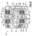
- Fig. 3 shows a heat transfer assembly 4050 comprising an evaporator 4010A, an absorber 4010B and a generator 4010C.
- the evaporator 4010A, the absorber 4010B and the generator 4010C each comprises a heat exchanger 4010 of the type shown in Fig. 1.
- the assembly 4050 also comprises a condenser 4052 which is of the standard type.
- Condensed heat transfer fluid, or refrigerant, 4036 is passed via a pipe 4054 and an expansion valve 4056 to the evaporator 4010A.
- the expansion valve 4056 expands the refrigerant 4036 passing therethrough to reduce its pressure.
- the reduced pressure refrigerant 4036 entering the evaporator 4010A passes onto the needles 4014A and to the reservoir 4034A where the scoop pipe 4028A disperses the refrigerant 4036 over the needles 4014A to enable evaporation to take place upon rotation of the spindle 4016A by the motor 4022A, thereby rotating the needles 4014A to enhance evaporation. This creates a refrigerating effect and fluid being passed through the reservoir 4034A via the conduits 4058 is cooled.
- the evaporated refrigerant 4036A is passed via the conduit 4042 to the absorber 4010B.
- a connecting rod 4020B extends from the spindle 4016A in the evaporator to the spindle 4016B in the absorber 4010B.
- the heat exchangers 4012A and B in the evaporator 4010A and the absorber 4010B are rotated synchronously by the motor 4022.
- the reservoir 4034B of the absorber 4010B holds a refrigerant/absorbent solution which is dispersed over the needles 4014B by the scoop pipe 4028B in the absorber 4010B. This causes the incoming evaporated refrigerant 4036A to be absorbed into the refrigerant/absorbent solution on the needles 4014. Heat of absorption is extracted from the reservoir 4034B of the absorber 4010B via fluid conduit 4060. A strong refrigerant/absorbent solution is passed via an outlet 4038B and a pump 4062, through a heat exchanger 4064 where the solution is heated. The solution is then passed by a pipe 4040C to the generator 4010C, and collects in the reservoir 4064C.
- Heat is supplied to the generator 4010C via the conduits 4066, and the scoop pipe 4028C disperses the refrigerant/absorbent solution over the needles 4014C whereby, upon rotation of the heat exchanger 4012C by the motor 4022C, the refrigerant is evaporated to be passed via the outlet 4042C to the condenser 4052.
- a weak refrigerant/absorbent solution is passed via the outlet 4038C through the evaporator 4064 to heat the fluid passing therethrough from the pipe 4038B. This results in the weak refrigerant/absorbent solution being cooled and this solution is then passed via the inlet conduit 4040B to the absorber 4010B for further absorption.
- the evaporated refrigerant in the outlet 4042C entering the condenser is condensed by cooling fluid passing through the conduits 4068. The cycle is then repeated.
- strong refrigerant/absorbent solution used herein refers to a solution having a high concentration of refrigerant.
- weak refrigerant/absorbent solution refers to a solution having a low concentration of refrigerant.
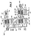
- FIG. 4 there is apparatus similar to that shown in Fig. 1, but which differs in that the standard condenser 4052 is replaced by heat exchange apparatus 4010D which is of the type shown in Fig. 24.
- the generator 4010C comprises heat exchanger 4012C, also of the type shown in Fig. 24, i.e. both including heat pipes 4018C,4018D.
- the operation of the evaporator 4010A and the absorber 4010B is the same as for Fig. 3, and will not be described below.
- the operation of the generator 4010C is similar to the generator 4010C shown in Fig. 3, with the exception that the conduit 4066 for heating the solution in the reservoir 4034C has been omitted.
- the heat exchanger 4012C and the heat exchanger 4012D are both rotated by means of the drive motor 4022D which is connected via the pulley 4024D and a belt 4026D to the heat pipe 4018D.
- Heat designated by the arrow A is supplied to the first end region 4044C and is transferred to the second end region 4046C of the heat pipe 4018C which causes refrigerant in the refrigerant/absorbent solution on the needles 4014C to be evaporated upon rotation thereof.
- the evaporated refrigerant passes along the conduit 4042C to the condenser 4010D to collect in the reservoir 4034D and to be dispersed over the needles 4016D by the scoop pipe 4028D.
- Heat is transferred along the heat pipe 4018D from the second end region 4046D to the first end region 4044D to be removed from the heat pipe 4018D as represented by the arrow B.
- the condensed refrigerant 4036 collects in the reservoir 4034D and is passed via the pipe 4054 to the evaporator 4010A via the expansion valve 4056.
- a heat transfer means which comprises the same components as the embodiment shown in Fig. 4 but operates in a different manner.
- Waste heat is fed to the generator 4010C via the heat pipe 4018C as shown by the arrow A and to the evaporator 4010A via the heating fluid in the conduit 4058.
- the heat fed to the heat pipe 4018C on the generator 4010C evaporates incoming refrigerant from strong refrigerant/absorbent solution entering from the conduit 4040C after having been expanded through an expansion valve 4041C so that the refrigerant/absorbent solution enters the generator 4010C at low pressure.
- the evaporated refrigerant generated by the generator 4010C passes via the conduit 4042C to the condenser 4010D, where heat is extracted from the refrigerant passing over the needles 4016D so that the refrigerant condenses on the needles 4016D and collects in the reservoir 4034D, at a low temperature. Heat is removed from the condenser 4010D via the heat pipe 4018D as shown by the arrow B.
- the absorbent from which the refrigerant has been evaporated collects in the reservoir 4034C of the generator 4010C and thereafter the weak refrigerant/absorbent solution is pumped by a pump 4063 to the absorber 4010B in the conduits 4038C and 4040B.
- a scoop pipe 4028C, rotating with the rotatable heat exchanger 4012C in the generator 4010C ensures that the needles 4014C are kept covered with the refrigerant/absorbent solution.
- the scoop pipe 4028D ensures that the needles 4014D of the rotatable heat exchanger 4012D are kept coated with condensed refrigerant.
- the condensed refrigerant in the reservoir 4034D is pumped by a pump 4065 via the conduit 4054 to the evaporator 4010A. Waste heat fed to the evaporator 4010A by fluid in the conduit 4058 to evaporate the refrigerant on the needles 4014A.
- the scoop pipe 4028A ensures that the needles 4014A are kept coated with the refrigerant.
- the evaporated refrigerant is passed via the conduit 4042A to the absorber 4010B where the refrigerant is absorbed by the absorbent on the needles 4014B giving out heat of absorption.
- the heat of absorption is removed by fluid in the conduit 4060.
- waste heat is fed into the system, at the generator 4010C and the evaporator 4010A at a moderate temperature, and by virtue of heat transfer in the system is removed at low temperature from the condenser, and at high temperature from the absorber.
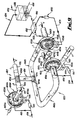
- FIG. 6 there is shown a perspective schematic view of a further embodiment of heat transfer assembly 4050 and comprises a generator 4010A, an absorber 4010B, and a generator 4070.
- the evaporator 4010A comprises a rotatable heat exchanger 4012A having a plurality of elongate needles 4014A mounted on a hollow spindle 4016A driven by a motor 4022 and a pulley 4024 and belt 4026 arrangement.
- refrigerant is fed via an expansion valve 4056 to the hollow spindle 4016A to be passed to the needles 4014A.
- Rotation of the heat exchanger 4012A by the motor 4022A causes refrigerant to move along the needles 4014A so that complete coverage of the needles 4014A is obtained.
- the refrigerant in the evaporator 4010A is evaporated and passes along the conduit 4042A to the absorber 4010B.
- the absorber 4010B receives via the conduit 4033B a weak refrigerant/absorbent solution via the hollow spindle 4016B to be spread over the needles 4014B by centrifugal forces.
- a strong refrigerant/absorbent solution is collected in the reservoir 4034B and is passed via the conduit 4038B to a holding tank 4072 via a filter 4074.
- the strong refrigerant/absorbent solution is then pumped via conduits 4074 by a pump 4076 to a heat exchanger 4064 to be heated thereby.
- the solution is then pumped via a conduit 4078 to the generator 4070.
- the generator 4070 comprises a solar collector 4080 to receive solar energy. This evaporates the refrigerant in the strong refrigerant/absorbent solution and a weak refrigerant/absorbent solution is collected in a collecting tank 4082.
- the weak refrigerant/absorbent solution which is now at a high temperature, is passed via the conduit 4084 to the heat exchanger 4064 to be cooled by the incoming solution through the conduit 4074.
- the weak refrigerant/absorbent solution is then passed by a conduit 4086 through a one way valve 4088 to a hydroseal 4090, and thereafter to a tank 4094 via the conduit 4092.
- the conduit 4092 extends through the tank 4094 and exits therefrom as conduit 4033B.
- the tank 4094 is in the form of a heat exchanger adapted to receive make-up water to replace the water evaporated at the generator 4070 via the conduit 4096. This cools the weak refrigerant/absorbent solution passing therethrough to the conduit 4033B. Conduits 4098 supply water to be cooled to the tank 4094 and extends therethrough and exits therefrom at a lower temperature.
- a heat transfer assembly 4050 which can be used, for example, in water desalination.
- the assembly 4050 comprises an evaporator 4010A, and an absorber 4010B, which operate in the same manner as the evaporators 4010A and the absorbers 4010B shown in Figs. 3 and 4.
- the only difference in the operation of the evaporator 4010A shown in Fig. 7 are that it receives incoming water to be desalinated from outside the assembly, rather than recycled water from the condenser, and the evaporator 4010A comprises an outlet conduit 4100 for discharging the concentrated salt solution therefrom.
- the salt solution is fed via an inlet pipe 4102 to the evaporator 4010A.
- the salt solution is dispersed over the needles 4014A and can collect in the reservoir 4034A.
- the incoming solution from the conduit 4102 is at a low pressure and is evaporated on the needles 4014A on rotation of the rotatable heat exchanger 4012A.
- a concentrated salt solution collects in the reservoir 4034A and this is discharged via the discharge conduit 4100.
- the evaporated refrigerant passes to the absorber 4010B where it is absorbed into an absorbent on the needles 4014B to form a strong refrigerant/absorbent solution.
- This solution is then pumped by a pump 4062A via a pipe 4038B to a heat exchanger to be heated and thereafter to the generator 4010C to be dispersed over the needles 4014C by the scoop pipe 4028C on rotation of the needles by the rotatable motor 4022C.
- Heat is supplied to the generator 4020C by conduit 4066 carrying heated fluid. This causes the refrigerant in the refrigerant/absorbent solution on the needles 4014C to be evaporated and thereafter passed via conduit 4042C to the condenser 4052 to be condensed thereby and thereafter the liquid water is passed via conduit 4104 to waste or storage.
- a de-humidification assembly which comprises an absorber 4010B, a generator 4010C, and a condenser 4010D.
- the absorber 4010B is of the type shown in Fig. 1, and comprises a rotatable heat exchanger 4012B comprising a spindle 4016B and a plurality of needles 4014B extending therefrom.
- Heat transfer apparatus 4010B further includes a reservoir 4032B to hold a refrigerant/absorbent solution 4036B and a scoop pipe 4028B for transferring a solution 4036B from the reservoir 4032B to the needles 4014B.
- incoming humid warm air is passed to the rotatable heat exchanger 4012B via an inlet 4104 as shown by the arrow C.
- the rotatable heat exchanger 4012B is rotated by the drive motor 4022 and the needles are covered in the absorbent solution 4036B. This absorbs water in the air entering the heat exchanger 4010B so that dry air heated by the heat absorption exits from the absorber 4010B via the outlet 4010C as shown by the arrow D.
- the absorption of the water into the absorbent 4036B produces a strong refrigerant/absorbent solution which is passed via conduit 4038B to heat exchanger 4064 to be heated and thereafter through conduit 4040C to the generator 4010C which is of a construction similar to the heat transfer apparatus shown in Fig. 24 and comprises a heat pipe 4018C to which heat is supplied to the first end region 4034C as shown by the arrow D. Heat is transferred along the heat pipe 4018C to the second end region 4046C to evaporate the refrigerant from the incoming refrigerant/absorbent solution.
- Evaporated refrigerant 4036C passes along the conduit 4042C, and the weak refrigerant/absorbent solution is pumped via the line 4038C by the pump 4062 to the heat exchanger 4064 to be cooled and thereafter passed by the line 4040B to the absorber 4010B.
- the refrigerant 4036C entering the condenser 4010D is condensed therein on the needles 4014D of the rotatable heat exchanger 4012D.
- the condensed refrigerant collects in the reservoir 4034D to be discharged therefrom via the outlet conduits 4108.
- Heat is removed from the heat pipe 4018D as shown by the arrow F, which means that heat is transferred from the second end region 4046D to the first end region 4044D to create the condensing effect.
- the rotatable heat exchangers 4012B,4012D are connected together by the elongate rod 4020C and are rotated by operation of the motor 4022D connected to the heat pipe 4018D by a pulley 4024D and belt 4026D.
- Fig. 9 shows an air conditioning assembly which comprises a first open cycle 4070 and a second open cycle 4072 thermodynamically connected by a heat pipe 4074.
- the first cycle 4070 comprises an absorber 4010B adapted to receive incoming air from outside the room or building to be cooled, as indicated by arrow 1.
- the air so entering passes along a conduit 4040B to a rotatable heat exchanger 4012B which can be rotated by a motor 4022B connected to the heat exchanger 4012B via a belt 4026B and pulley 4024B system and a spindle 4025B.
- a spindle 4025A extends to a first evaporator 4010A as will be explained below.
- An absorbent is passed via a conduit 4076 to the needles 4014B of the rotary heat exchanger 4012B whereby water in the incoming air is absorbed.
- Heat of absorption warms the incoming air, and the warmed dried air is passed via an outlet conduit 4042B towards a first evaporator 4010A.
- the strong refrigerant/absorbent solution i.e. the solution which is the result of the water in the air being absorbed in the absorbent, is collected in a reservoir 4034B and pumped via a conduit 4078 by a pump 4080 to a heat exchanger 4082 to be further warmed. Thereafter the strong absorbent/refrigerant solution is passed via a conduit 4084 to a generator 4086, in which a heating element 4088 causes the water in the solution to be evaporated and passed to the atmosphere as shown at 4090.
- the weak refrigerant/absorbent solution is then passed via a conduit 4092 to the heat exchanger 4082 to be cooled and thereafter passed via conduit 4076 to the absorber 4010B.
- the warmed dried air in the conduit 4042B passes over a first end region 4074A of the heat pipe 4074 where heat is transferred via fins 4094 to the heat pipe 4074 to transfer heat to the second cycle 4072 as will be explained below.
- the air in the conduit 4042B is cooled and passes therefrom via a conduit 4040A to the first evaporator 4010A which includes a rotatable heat exchanger 4012A having needles 4014A.
- the rotatable heat exchanger is rotated by means of the motor 4022B which operates via a belt 4026B and a pulley 4024B to transmit the rotational force of the motor to the rotary heat exchanger 4012A via a spindle 4025A.
- a refrigerant, in the form of water is fed to the rotary heat exchanger via a conduit 4096 to coat the needles 4014A. Evaporation of the water on the needles cools the air entering the evaporator 4010A and increases the humidity of the air. Cooled humid air exits from the evaporator 4010A via a conduit 4102 as shown by the arrow Y to the room or building to be cooled.
- Unevaporated water is collected in a reservoir 4034A to be recycled back to the evaporator 4010A by a pump 4097 via a conduit 4098 and the conduit 4096.
- the water lost by evaporation is replaced by incoming water via the conduit 4100.
- the second cycle 4072 comprises a second evaporator 4010AA adapted to receive warm air from the room or building to be cooled via a conduit 101.
- the second evaporator 4010AA comprises a rotatable heat exchanger 4012AA.
- a refrigerant e.g. water is passed via a conduit 4102 onto the needles 4014AA of the rotatable heat exchanger 4012AA, which is rotated by a motor 4022AA.
- the water is -evaporated on the needles 4012AA which cools and humidifies the incoming air from the conduit 4101.
- the cooled, humidified air is then passed via a conduit 4104 over a second end region 4074B of the heat pipe 4074 whereby heat is transferred via fins 4094B from the heat pipe 4074 to the air in the conduit 4104, thereby warming it.
- the warmed air is then exhausted via a conduit 4106 to atmosphere, as shown by arrow Z.
- Unevaporated water is collected in a reservoir 4034AA to be recycled by a pump 4105 back to the rotatable heat exchanger 4012AA via conduits 4106 and 4102 along with incoming water from conduit 4108 to replace water lost by evaporation.
- Fig. 10 there is shown a psychrometic chart showing the changes in temperature and humidity of the air as it passes through the two cycles of the apparatus shown in Fig. 9.
- Fig. 10 is cross-referenced with Fig. 9, it will be seen that there are four ringed numbers 1,2,3 and 4, and these ringed letters A,B, and C. Each of these represent a point on the psychrometic chart in Fig. 10 which has been designated with the same number or letter.
- the air passing between points 2 and 3 reduces in temperature as the air passes over the first end region 4074A of the heat pipe 4074 which extracts heat from the air.
- the air passing between points 3 and 4 increases in humidity and decreases in temperature, as the evaporator cools the air by evaporation and the evaporated water humidifies the air.
- cooled air is passed into the room of building to be cooled.
- the air passing between points B and C increases in temperature as the air passes of the second end region 4074B of the heat pipe 4074 to extract heat therefrom.
Landscapes
- Engineering & Computer Science (AREA)
- General Engineering & Computer Science (AREA)
- Mechanical Engineering (AREA)
- Chemical & Material Sciences (AREA)
- Combustion & Propulsion (AREA)
- Physics & Mathematics (AREA)
- Thermal Sciences (AREA)
- Sustainable Development (AREA)
- Life Sciences & Earth Sciences (AREA)
- Sustainable Energy (AREA)
- Chemical Kinetics & Catalysis (AREA)
- Sorption Type Refrigeration Machines (AREA)
- Thermotherapy And Cooling Therapy Devices (AREA)
- Gloves (AREA)
- Power Steering Mechanism (AREA)
- Heat-Exchange Devices With Radiators And Conduit Assemblies (AREA)
- Heating, Cooling, Or Curing Plastics Or The Like In General (AREA)
Abstract
Description
Claims (23)
- Heat transfer apparatus comprising a rotatable heat exchanger (4012) comprising a rotatable shaft, the apparatus further including drive means (4022) for rotating the heat exchanger (4012), and supply means (4040) for supplying a heat transfer fluid (4036) to the rotatable heat exchanger, characterised in that the rotatable heat exchanger further includes a plurality of elongate elements (4014) extending outwardly from the rotatable shaft, each element (4014) having an outwardly extending dimension which is greater than the diameter of the shaft, whereby when the heat exchanger (4012) is rotated, heat can be transferred to or from the heat transfer fluid (4036) at said elongate elements (4014).
- Heat transfer apparatus according to Claim 1, characterised in that the elongate elements (4014) comprise fins in the form of spines, needles or narrow strips.
- Heat transfer apparatus according to Claim 1 or 2, characterised by a housing (4032) for the rotatable heat exchanger (4012), the housing (4032) including a reservoir (4034) to hold the heat transfer fluid (4036), and the apparatus further including collection means to collect some of said fluid (4036) and deliver the fluid (4036) to the elongate elements (4014) of the rotatable heat exchanger (4012).
- Heat transfer apparatus according to Claim 3, characterised in that the collection means comprises a pipe (4028) rotatable with said rotatable heat exchanger (4012), and being fixedly mounted on the shaft for rotation.
- Heat transfer apparatus according to Claims 1,2, 3 or 4, characterised in that the rotatable shaft comprises a heat pipe (4018) capable of transferring heat from one end region thereof to the opposite end region, upon which heat pipe (4018) the elongate elements (4014) are fixedly mounted.
- Heat transfer apparatus according to Claims 1, 2, 3, or 4, characterised in that the rotatable shaft comprises a spindle upon which the elongate elements are mounted.
- A heat transfer assembly characterised by a heat transfer apparatus (4010) as claimed in any preceding claims connected to at least one further heat transfer apparatus for transferring the heat transfer fluid from one region of the assembly to another thereby transferring heat from one region of the assembly to another.
- A heat transfer assembly according to Claim 7, characterised in that the, at least one, or each, of said further heat transfer apparatus is in the form of a heat transfer apparatus (4010) as claimed in Claims 1 to 6.
- A heat transfer assembly according to Claims 7 characterised by including at least one of the following: an evaporator for evaporating expanded heat transfer fluid, an absorber to receive said evaporated heat transfer fluid from the evaporator, the absorber containing an absorbent to absorb said heat transfer fluid, to produce a strong heat transfer fluid/absorbent solution; a generator for receiving said strong solution to generate evaporated heat transfer fluid and to produce a weak heat transfer fluid/absorbent solution; and a condenser to receive and condense said evaporated heat transfer fluid from the generator, at least one of the, evaporator, absorber, generator, and condenser comprises a heat transfer apparatus claimed in Claims 1 to 6.
- A heat transfer assembly according to Claim 9, characterised in that the assembly is in the form of a cycle whereby the condensed heat transfer fluid is supplied from the condenser to the evaporator preferably via expansion means to expand the heat transfer fluid, thereby reducing the pressure thereof.
- A heat transfer assembly according to Claims 9 or 10, characterised in that the shafts of the rotatable heat exchangers of the generator and the condenser comprise heat pipes.
- A heat transfer assembly according to Claim 9 or 10, characterised in that the assembly comprises an open cycle whereby heat transfer fluid is evaporated away at the generator.
- A heat transfer assembly according to Claim 12, characterised in that the generator is solar powered and includes a solar collector, and feed means is provided to feed further refrigerant to the assembly.
- A heat transfer assembly according to Claim 9 or 10, characterised in that the assembly provides an open cycle including feed means for feeding a solution comprising the heat transfer fluid as the solvent, to the evaporator for evaporation of the heat transfer fluid therefrom, and condensate discharge means for discharging condensed heat transfer fluid from the condenser.
- A heat transfer assembly according to Claim 14, characterised in that including solvent discharge means for discharging the concentrated solution from the evaporator.
- A heat transfer assembly according to Claim 9 or 10, characterised in that the assembly is in the form of an open cycle for drying applications when the heat transfer fluid comprises water, whereby the absorber may include an inlet for receiving humid air and an outlet for discharging dry air, the absorbent being adapted to absorb the water in the air.
- A heat transfer assembly according to Claim 16, characterised in that the condenser is provided with a water outlet whereby condensed water can be discharged.
- A heat transfer assembly according to Claim 9 or 10, characterised in that the assembly comprises two cycles connected by heat transfer means.
- A heat transfer assembly according to Claim 18, characterised in that the first cycle of the assembly comprises an absorber to receive warm humid air to remove the moisture from said air thereby drying the air an evaporator to receive the dried air, and to receive a heat transfer fluid, whereby the heat transfer fluid is evaporated to cool and humidify the incoming dry air, thereby to produce cooled moist air therefrom.
- A heat transfer assembly according to Claim 19, characterised in that heat transfer means is arranged between the absorber and the evaporator to transfer heat from the first cycle to the second cycle.
- A heat transfer assembly according to Claim 20, characterised in that the heat transfer means is a heat pipe, one end region of which is arranged in the path between the absorber and the evaporator.
- A heat transfer assembly according to Claim 21, characterised in that the second cycle comprises an evaporator for receiving warm air, and to receive a heat transfer fluid, whereby the heat transfer fluid is evaporated to cool and humidify the air, and further includes exhaust means, to exhaust the humidified air, the heat transfer means being arranged between the evaporator and the exhaust means of the second cycle, whereby the opposite end region of the heat transfer means is arranged in the path of the air between the evaporator and the exhaust means.
- A heat transfer assembly according to Claim 22, characterised in that the evaporator and the absorber of the first cycle and the evaporator of the second cycle each comprise a heat transfer apparatus as claimed in any of Claims 1 to 6.
Applications Claiming Priority (9)
| Application Number | Priority Date | Filing Date | Title |
|---|---|---|---|
| GB9522930 | 1995-11-10 | ||
| GBGB9522930.8A GB9522930D0 (en) | 1995-11-10 | 1995-11-10 | Improvements in or relating to power generating apparatus |
| GBGB9524168.3A GB9524168D0 (en) | 1995-11-25 | 1995-11-25 | Heat transfer apparatus |
| GB9524168 | 1995-11-25 | ||
| GB9604988 | 1996-03-08 | ||
| GBGB9604988.7A GB9604988D0 (en) | 1996-03-08 | 1996-03-08 | Improvements in or relating to heat transfer apparatus |
| GBGB9614106.4A GB9614106D0 (en) | 1996-07-05 | 1996-07-05 | Heat transfer apparatus |
| GB9614106 | 1996-07-05 | ||
| PCT/GB1996/002704 WO1997017585A1 (en) | 1995-11-10 | 1996-11-05 | Rotatable heat transfer apparatus |
Publications (2)
| Publication Number | Publication Date |
|---|---|
| EP0859940A1 EP0859940A1 (en) | 1998-08-26 |
| EP0859940B1 true EP0859940B1 (en) | 2002-10-02 |
Family
ID=27451361
Family Applications (1)
| Application Number | Title | Priority Date | Filing Date |
|---|---|---|---|
| EP96935172A Expired - Lifetime EP0859940B1 (en) | 1995-11-10 | 1996-11-05 | Rotatable heat transfer apparatus |
Country Status (7)
| Country | Link |
|---|---|
| US (1) | US6158237A (en) |
| EP (1) | EP0859940B1 (en) |
| JP (1) | JP2000500221A (en) |
| AT (1) | ATE225490T1 (en) |
| AU (1) | AU7324496A (en) |
| DE (1) | DE69624126T2 (en) |
| WO (1) | WO1997017585A1 (en) |
Cited By (1)
| Publication number | Priority date | Publication date | Assignee | Title |
|---|---|---|---|---|
| US10323863B2 (en) | 2015-05-12 | 2019-06-18 | Carrier Kältetechnik Deutschland Gmbh | Ejector refrigeration circuit |
Families Citing this family (71)
| Publication number | Priority date | Publication date | Assignee | Title |
|---|---|---|---|---|
| JP3591356B2 (en) * | 1999-02-03 | 2004-11-17 | 株式会社日立製作所 | Absorption refrigerator and method of manufacturing the same |
| US6430937B2 (en) * | 2000-03-03 | 2002-08-13 | Vai Holdings, Llc | Vortex generator to recover performance loss of a refrigeration system |
| DE10294304D2 (en) * | 2001-09-14 | 2004-10-14 | Alexander Luchinskiy | Method and device for converting energy |
| US6990797B2 (en) * | 2003-09-05 | 2006-01-31 | General Electric Company | Methods and apparatus for operating gas turbine engines |
| US6938422B2 (en) * | 2003-10-28 | 2005-09-06 | Jeffrey P. Thorn | Ambient energy fueled mechanical and electric power plant (AEFMEPP) |
| ES2305529T3 (en) * | 2003-11-21 | 2008-11-01 | Rotartica, S.A. | HEAT PUMP BY ROTATING ABSORPTION CYCLE. |
| US7347049B2 (en) * | 2004-10-19 | 2008-03-25 | General Electric Company | Method and system for thermochemical heat energy storage and recovery |
| US7458413B2 (en) * | 2004-11-12 | 2008-12-02 | International Business Machines Corporation | Semiconductor chip heat transfer device |
| US20060131003A1 (en) * | 2004-12-20 | 2006-06-22 | Je-Young Chang | Apparatus and associated method for microelectronic cooling |
| GR20050100002A (en) * | 2005-01-07 | 2006-09-21 | PRODUCTION OF ELECTRICITY WITH HOT WATER SOLAR COLLECTORS AND PRESSURE AMMONIUM Vapor Powered by Power Generator | |
| US7565808B2 (en) * | 2005-01-13 | 2009-07-28 | Greencentaire, Llc | Refrigerator |
| RU2388982C2 (en) * | 2005-10-10 | 2010-05-10 | Эмджи Инновейшнз Корп. | Heat exchange device (versions) |
| JP4322902B2 (en) * | 2006-08-10 | 2009-09-02 | 川崎重工業株式会社 | Solar power generation equipment and heat medium supply equipment |
| DE102007012113B4 (en) * | 2007-03-13 | 2009-04-16 | Sortech Ag | Compact sorption refrigeration device |
| US7726135B2 (en) * | 2007-06-06 | 2010-06-01 | Greencentaire, Llc | Energy transfer apparatus and methods |
| US20090071155A1 (en) * | 2007-09-14 | 2009-03-19 | General Electric Company | Method and system for thermochemical heat energy storage and recovery |
| US20100060005A1 (en) * | 2008-09-05 | 2010-03-11 | Bhatti Mohinder S | Power generation system using low grade solar energy |
| RU2406945C2 (en) * | 2008-10-29 | 2010-12-20 | Государственное образовательное учреждение высшего профессионального образования "Курский государственный технический университет" | Thermal-pipe steam-ejector cooling machine |
| US20100186409A1 (en) * | 2009-01-26 | 2010-07-29 | Thomas Hertel | Rankine cycle with multiple configuration of vortex |
| US8616323B1 (en) | 2009-03-11 | 2013-12-31 | Echogen Power Systems | Hybrid power systems |
| US20100251759A1 (en) * | 2009-04-03 | 2010-10-07 | Occhipinti Gasper C | Liquid pressure cycle having an ejector |
| US9014791B2 (en) | 2009-04-17 | 2015-04-21 | Echogen Power Systems, Llc | System and method for managing thermal issues in gas turbine engines |
| JP5681711B2 (en) | 2009-06-22 | 2015-03-11 | エコージェン パワー システムズ インコーポレイテッドEchogen Power Systems Inc. | Heat effluent treatment method and apparatus in one or more industrial processes |
| EP2445613A1 (en) | 2009-06-25 | 2012-05-02 | VTU Holding GmbH | Method of use of an ionic liquid and device for sorption of a gas |
| HRP20170573T1 (en) * | 2009-07-20 | 2017-06-16 | National University Of Singapore | Desalination system and method |
| US9316404B2 (en) | 2009-08-04 | 2016-04-19 | Echogen Power Systems, Llc | Heat pump with integral solar collector |
| EP2499442A2 (en) * | 2009-09-06 | 2012-09-19 | Ben-gurion University Of The Negev Research And Development Authority | Air cooled absorption cooling system operable by low grade heat |
| US8869531B2 (en) | 2009-09-17 | 2014-10-28 | Echogen Power Systems, Llc | Heat engines with cascade cycles |
| US8613195B2 (en) | 2009-09-17 | 2013-12-24 | Echogen Power Systems, Llc | Heat engine and heat to electricity systems and methods with working fluid mass management control |
| US9115605B2 (en) | 2009-09-17 | 2015-08-25 | Echogen Power Systems, Llc | Thermal energy conversion device |
| US8813497B2 (en) | 2009-09-17 | 2014-08-26 | Echogen Power Systems, Llc | Automated mass management control |
| RU2012116504A (en) * | 2009-09-25 | 2013-10-27 | ДАУ ГЛОБАЛ ТЕКНОЛОДЖИЗ ЭлЭлСи | HEAT TRANSMISSION SYSTEM USING MATERIALS ACCUMULATING HEAT ENERGY |
| US8904791B2 (en) | 2010-11-19 | 2014-12-09 | General Electric Company | Rankine cycle integrated with organic rankine cycle and absorption chiller cycle |
| US8783034B2 (en) | 2011-11-07 | 2014-07-22 | Echogen Power Systems, Llc | Hot day cycle |
| US8857186B2 (en) | 2010-11-29 | 2014-10-14 | Echogen Power Systems, L.L.C. | Heat engine cycles for high ambient conditions |
| US8616001B2 (en) | 2010-11-29 | 2013-12-31 | Echogen Power Systems, Llc | Driven starter pump and start sequence |
| JP5761205B2 (en) * | 2011-01-24 | 2015-08-12 | 富士通株式会社 | Adsorber and adsorption heat pump |
| US9062898B2 (en) | 2011-10-03 | 2015-06-23 | Echogen Power Systems, Llc | Carbon dioxide refrigeration cycle |
| US20130105110A1 (en) * | 2011-10-28 | 2013-05-02 | Lockheed Martin Corporation | Integrated absorption-cycle refrigeration and power generation system |
| JP5482767B2 (en) * | 2011-11-17 | 2014-05-07 | 株式会社デンソー | Ejector refrigeration cycle |
| CN102692092B (en) * | 2011-12-25 | 2014-10-08 | 河南科技大学 | Jet type refrigeration system with expander |
| KR20150143402A (en) | 2012-08-20 | 2015-12-23 | 에코진 파워 시스템스, 엘엘씨 | Supercritical working fluid circuit with a turbo pump and a start pump in series configuration |
| US9080796B2 (en) * | 2012-08-27 | 2015-07-14 | Ford Global Technologies, Llc | Motor vehicle climate control system |
| WO2014042580A1 (en) * | 2012-09-12 | 2014-03-20 | Climeon Ab | Method for improving the performance of thermodynamic cycles |
| US9341084B2 (en) | 2012-10-12 | 2016-05-17 | Echogen Power Systems, Llc | Supercritical carbon dioxide power cycle for waste heat recovery |
| US9118226B2 (en) | 2012-10-12 | 2015-08-25 | Echogen Power Systems, Llc | Heat engine system with a supercritical working fluid and processes thereof |
| JP6089721B2 (en) * | 2013-01-23 | 2017-03-08 | アイシン精機株式会社 | Absorption heat pump device |
| WO2014117074A1 (en) | 2013-01-28 | 2014-07-31 | Echogen Power Systems, L.L.C. | Process for controlling a power turbine throttle valve during a supercritical carbon dioxide rankine cycle |
| US9638065B2 (en) | 2013-01-28 | 2017-05-02 | Echogen Power Systems, Llc | Methods for reducing wear on components of a heat engine system at startup |
| EP2964911B1 (en) | 2013-03-04 | 2022-02-23 | Echogen Power Systems LLC | Heat engine systems with high net power supercritical carbon dioxide circuits |
| CN103629860B (en) * | 2013-12-04 | 2015-09-16 | 重庆大学 | Trans-critical cycle CO 2cool and thermal power combined cycle system |
| JP6264013B2 (en) * | 2013-12-16 | 2018-01-24 | アイシン精機株式会社 | Absorption heat pump device |
| US20150211805A1 (en) * | 2014-01-29 | 2015-07-30 | Kunshan Jue-Chung Electronics Co., Ltd. | Thermostat module |
| JP2017529510A (en) | 2014-09-19 | 2017-10-05 | アクシオム エクセルギー インコーポレイテッドAxiom Exergy Inc. | System and method for implementing a robust air conditioning system configured to maintain a target space at a low temperature using thermal energy storage |
| US10570777B2 (en) | 2014-11-03 | 2020-02-25 | Echogen Power Systems, Llc | Active thrust management of a turbopump within a supercritical working fluid circuit in a heat engine system |
| US9528731B2 (en) * | 2015-04-23 | 2016-12-27 | King Fahd University Of Petroleum And Minerals | Solar powered cooling system |
| JP6142895B2 (en) * | 2015-04-28 | 2017-06-07 | 株式会社豊田中央研究所 | heat pump |
| JP6403703B2 (en) * | 2016-02-19 | 2018-10-10 | 有限会社泰栄産業 | Method and apparatus for cooling and drying compressed air |
| US11187112B2 (en) | 2018-06-27 | 2021-11-30 | Echogen Power Systems Llc | Systems and methods for generating electricity via a pumped thermal energy storage system |
| US10890384B2 (en) * | 2019-02-22 | 2021-01-12 | Alfa Laval Corporate Ab | Plate heat exchanger |
| US11435120B2 (en) | 2020-05-05 | 2022-09-06 | Echogen Power Systems (Delaware), Inc. | Split expansion heat pump cycle |
| US11397030B2 (en) * | 2020-07-10 | 2022-07-26 | Energy Recovery, Inc. | Low energy consumption refrigeration system with a rotary pressure exchanger replacing the bulk flow compressor and the high pressure expansion valve |
| US11421918B2 (en) | 2020-07-10 | 2022-08-23 | Energy Recovery, Inc. | Refrigeration system with high speed rotary pressure exchanger |
| CN112161360B (en) * | 2020-09-19 | 2022-02-18 | 海易(大连)实业有限公司 | Humidification device convenient to adjust humidity for biotechnology research |
| US11629638B2 (en) | 2020-12-09 | 2023-04-18 | Supercritical Storage Company, Inc. | Three reservoir electric thermal energy storage system |
| US20220216485A1 (en) * | 2021-01-05 | 2022-07-07 | Alexander Charles Kurple | Power generation and energy storage in thermal batteries |
| US12007154B2 (en) | 2021-06-09 | 2024-06-11 | Energy Recovery, Inc. | Heat pump systems with pressure exchangers |
| US12209778B2 (en) | 2021-06-09 | 2025-01-28 | Energy Recovery, Inc. | Refrigeration and heat pump systems with pressure exchangers |
| US12516855B2 (en) | 2022-10-27 | 2026-01-06 | Supercritical Storage Company, Inc. | High-temperature, dual rail heat pump cycle for high performance at high-temperature lift and range |
| WO2025010090A1 (en) | 2023-02-07 | 2025-01-09 | Supercritical Storage Company, Inc. | Waste heat integration into pumped thermal energy storage |
| WO2024180762A1 (en) * | 2023-03-02 | 2024-09-06 | 三菱電機株式会社 | Light source system |
Family Cites Families (6)
| Publication number | Priority date | Publication date | Assignee | Title |
|---|---|---|---|---|
| BE565756A (en) * | ||||
| US3544084A (en) * | 1968-09-16 | 1970-12-01 | Lawrence Macrow | Drum for intimately contacting gas and liquid |
| US3605436A (en) * | 1969-08-29 | 1971-09-20 | Oscar Elbridge Gammill Jr | Centrifugal absorption air conditioner |
| US5249436A (en) * | 1992-04-09 | 1993-10-05 | Indugas, Inc. | Simplified, low cost absorption heat pump |
| JPH0765836B2 (en) * | 1992-11-27 | 1995-07-19 | 晃 伊藤 | Cooling system |
| US5303565A (en) * | 1993-03-11 | 1994-04-19 | Conserve Resources, Inc. | Rotary absorption heat pump of improved performance |
-
1996
- 1996-11-05 AU AU73244/96A patent/AU7324496A/en not_active Abandoned
- 1996-11-05 US US09/068,256 patent/US6158237A/en not_active Expired - Fee Related
- 1996-11-05 DE DE69624126T patent/DE69624126T2/en not_active Expired - Fee Related
- 1996-11-05 WO PCT/GB1996/002704 patent/WO1997017585A1/en not_active Ceased
- 1996-11-05 JP JP9517971A patent/JP2000500221A/en active Pending
- 1996-11-05 AT AT96935172T patent/ATE225490T1/en not_active IP Right Cessation
- 1996-11-05 EP EP96935172A patent/EP0859940B1/en not_active Expired - Lifetime
Cited By (1)
| Publication number | Priority date | Publication date | Assignee | Title |
|---|---|---|---|---|
| US10323863B2 (en) | 2015-05-12 | 2019-06-18 | Carrier Kältetechnik Deutschland Gmbh | Ejector refrigeration circuit |
Also Published As
| Publication number | Publication date |
|---|---|
| DE69624126D1 (en) | 2002-11-07 |
| US6158237A (en) | 2000-12-12 |
| EP0859940A1 (en) | 1998-08-26 |
| AU7324496A (en) | 1997-05-29 |
| JP2000500221A (en) | 2000-01-11 |
| DE69624126T2 (en) | 2003-05-28 |
| WO1997017585A1 (en) | 1997-05-15 |
| ATE225490T1 (en) | 2002-10-15 |
Similar Documents
| Publication | Publication Date | Title |
|---|---|---|
| US6158237A (en) | Rotatable heat transfer apparatus | |
| US4287721A (en) | Chemical heat pump and method | |
| CN1129753C (en) | Absorption heat pump and desiccant assisted air conditioning apparatus | |
| CN101175898B (en) | System and method for managing water content in a fluid | |
| EP1121565B1 (en) | heat exchange refrigerant subcool and/or precool system and method | |
| US7194870B1 (en) | High performance dehumidifier | |
| KR20000012768A (en) | Dry apparatus | |
| IL163015A (en) | Systems and methods for dehumidification | |
| EP2156116A1 (en) | Evaporative cooler and desiccant assisted vapor compression ac system | |
| US6006538A (en) | Air conditioner energy system | |
| CN206787265U (en) | Dehumidifying drying integration unit | |
| JPS62180720A (en) | Dehumidifier | |
| CN117663302A (en) | Circulating air dehumidifier | |
| CN112250130B (en) | A multi-mode water purification system based on humidification and dehumidification process | |
| JP2000356481A (en) | Heat exchanger, heat pump and dehumidifier | |
| KR100530751B1 (en) | Composite energy generating system | |
| GB1583201A (en) | Air conditioning apparatus utilizing solar energy and method | |
| CN219389933U (en) | Energy-saving rotary dehumidifier | |
| CA2237146A1 (en) | Rotatable heat transfer apparatus | |
| JP2004069087A (en) | Air conditioner using cogeneration system | |
| KR101989428B1 (en) | Humidity and heat exchanger | |
| SU1270495A1 (en) | Method of heat and moisture treatment of air in conditioning systems | |
| SU943487A1 (en) | Rotary heat exchanger | |
| WO2020193984A1 (en) | Cooling apparatus, method of cooling and air conditioning apparatus | |
| CZ142598A3 (en) | Rotary apparatus for transfer of heat |
Legal Events
| Date | Code | Title | Description |
|---|---|---|---|
| PUAI | Public reference made under article 153(3) epc to a published international application that has entered the european phase |
Free format text: ORIGINAL CODE: 0009012 |
|
| 17P | Request for examination filed |
Effective date: 19980529 |
|
| AK | Designated contracting states |
Kind code of ref document: A1 Designated state(s): AT BE CH DE ES FI FR GB GR IE IT LI NL SE |
|
| 17Q | First examination report despatched |
Effective date: 19980902 |
|
| GRAG | Despatch of communication of intention to grant |
Free format text: ORIGINAL CODE: EPIDOS AGRA |
|
| GRAG | Despatch of communication of intention to grant |
Free format text: ORIGINAL CODE: EPIDOS AGRA |
|
| GRAG | Despatch of communication of intention to grant |
Free format text: ORIGINAL CODE: EPIDOS AGRA |
|
| GRAH | Despatch of communication of intention to grant a patent |
Free format text: ORIGINAL CODE: EPIDOS IGRA |
|
| GRAH | Despatch of communication of intention to grant a patent |
Free format text: ORIGINAL CODE: EPIDOS IGRA |
|
| GRAA | (expected) grant |
Free format text: ORIGINAL CODE: 0009210 |
|
| AK | Designated contracting states |
Kind code of ref document: B1 Designated state(s): AT BE CH DE ES FI FR GB GR IE IT LI NL SE |
|
| PG25 | Lapsed in a contracting state [announced via postgrant information from national office to epo] |
Ref country code: NL Free format text: LAPSE BECAUSE OF FAILURE TO SUBMIT A TRANSLATION OF THE DESCRIPTION OR TO PAY THE FEE WITHIN THE PRESCRIBED TIME-LIMIT Effective date: 20021002 Ref country code: LI Free format text: LAPSE BECAUSE OF FAILURE TO SUBMIT A TRANSLATION OF THE DESCRIPTION OR TO PAY THE FEE WITHIN THE PRESCRIBED TIME-LIMIT Effective date: 20021002 Ref country code: IT Free format text: LAPSE BECAUSE OF FAILURE TO SUBMIT A TRANSLATION OF THE DESCRIPTION OR TO PAY THE FEE WITHIN THE PRE;WARNING: LAPSES OF ITALIAN PATENTS WITH EFFECTIVE DATE BEFORE 2007 MAY HAVE OCCURRED AT ANY TIME BEFORE 2007. THE CORRECT EFFECTIVE DATE MAY BE DIFFERENT FROM THE ONE RECORDED.SCRIBED TIME-LIMIT Effective date: 20021002 Ref country code: FI Free format text: LAPSE BECAUSE OF FAILURE TO SUBMIT A TRANSLATION OF THE DESCRIPTION OR TO PAY THE FEE WITHIN THE PRESCRIBED TIME-LIMIT Effective date: 20021002 Ref country code: CH Free format text: LAPSE BECAUSE OF FAILURE TO SUBMIT A TRANSLATION OF THE DESCRIPTION OR TO PAY THE FEE WITHIN THE PRESCRIBED TIME-LIMIT Effective date: 20021002 Ref country code: BE Free format text: LAPSE BECAUSE OF FAILURE TO SUBMIT A TRANSLATION OF THE DESCRIPTION OR TO PAY THE FEE WITHIN THE PRESCRIBED TIME-LIMIT Effective date: 20021002 Ref country code: AT Free format text: LAPSE BECAUSE OF FAILURE TO SUBMIT A TRANSLATION OF THE DESCRIPTION OR TO PAY THE FEE WITHIN THE PRESCRIBED TIME-LIMIT Effective date: 20021002 |
|
| REF | Corresponds to: |
Ref document number: 225490 Country of ref document: AT Date of ref document: 20021015 Kind code of ref document: T |
|
| REG | Reference to a national code |
Ref country code: GB Ref legal event code: FG4D |
|
| REG | Reference to a national code |
Ref country code: CH Ref legal event code: EP |
|
| REG | Reference to a national code |
Ref country code: IE Ref legal event code: FG4D |
|
| PG25 | Lapsed in a contracting state [announced via postgrant information from national office to epo] |
Ref country code: IE Free format text: LAPSE BECAUSE OF NON-PAYMENT OF DUE FEES Effective date: 20021105 |
|
| REF | Corresponds to: |
Ref document number: 69624126 Country of ref document: DE Date of ref document: 20021107 |
|
| PGFP | Annual fee paid to national office [announced via postgrant information from national office to epo] |
Ref country code: FR Payment date: 20021227 Year of fee payment: 7 |
|
| PGFP | Annual fee paid to national office [announced via postgrant information from national office to epo] |
Ref country code: DE Payment date: 20021230 Year of fee payment: 7 |
|
| PG25 | Lapsed in a contracting state [announced via postgrant information from national office to epo] |
Ref country code: SE Free format text: LAPSE BECAUSE OF FAILURE TO SUBMIT A TRANSLATION OF THE DESCRIPTION OR TO PAY THE FEE WITHIN THE PRESCRIBED TIME-LIMIT Effective date: 20030102 |
|
| REG | Reference to a national code |
Ref country code: GR Ref legal event code: EP Ref document number: 20020404507 Country of ref document: GR |
|
| PGFP | Annual fee paid to national office [announced via postgrant information from national office to epo] |
Ref country code: GR Payment date: 20030219 Year of fee payment: 7 |
|
| NLV1 | Nl: lapsed or annulled due to failure to fulfill the requirements of art. 29p and 29m of the patents act | ||
| ET | Fr: translation filed | ||
| PG25 | Lapsed in a contracting state [announced via postgrant information from national office to epo] |
Ref country code: ES Free format text: LAPSE BECAUSE OF FAILURE TO SUBMIT A TRANSLATION OF THE DESCRIPTION OR TO PAY THE FEE WITHIN THE PRESCRIBED TIME-LIMIT Effective date: 20030429 |
|
| REG | Reference to a national code |
Ref country code: CH Ref legal event code: PL |
|
| PLBE | No opposition filed within time limit |
Free format text: ORIGINAL CODE: 0009261 |
|
| STAA | Information on the status of an ep patent application or granted ep patent |
Free format text: STATUS: NO OPPOSITION FILED WITHIN TIME LIMIT |
|
| REG | Reference to a national code |
Ref country code: IE Ref legal event code: MM4A |
|
| 26N | No opposition filed |
Effective date: 20030703 |
|
| PG25 | Lapsed in a contracting state [announced via postgrant information from national office to epo] |
Ref country code: DE Free format text: LAPSE BECAUSE OF NON-PAYMENT OF DUE FEES Effective date: 20040602 |
|
| PG25 | Lapsed in a contracting state [announced via postgrant information from national office to epo] |
Ref country code: GR Free format text: LAPSE BECAUSE OF NON-PAYMENT OF DUE FEES Effective date: 20040603 |
|
| PG25 | Lapsed in a contracting state [announced via postgrant information from national office to epo] |
Ref country code: FR Free format text: LAPSE BECAUSE OF NON-PAYMENT OF DUE FEES Effective date: 20041029 |
|
| REG | Reference to a national code |
Ref country code: FR Ref legal event code: ST |
|
| PGFP | Annual fee paid to national office [announced via postgrant information from national office to epo] |
Ref country code: GB Payment date: 20061031 Year of fee payment: 11 |
|
| GBPC | Gb: european patent ceased through non-payment of renewal fee |
Effective date: 20071105 |
|
| PG25 | Lapsed in a contracting state [announced via postgrant information from national office to epo] |
Ref country code: FR Free format text: LAPSE BECAUSE OF NON-PAYMENT OF DUE FEES Effective date: 20031130 |
|
| PG25 | Lapsed in a contracting state [announced via postgrant information from national office to epo] |
Ref country code: GB Free format text: LAPSE BECAUSE OF NON-PAYMENT OF DUE FEES Effective date: 20071105 |