EP0859882B1 - Mat anisotrope de fils de verre continus et procede de fabrication - Google Patents
Mat anisotrope de fils de verre continus et procede de fabrication Download PDFInfo
- Publication number
- EP0859882B1 EP0859882B1 EP97938978A EP97938978A EP0859882B1 EP 0859882 B1 EP0859882 B1 EP 0859882B1 EP 97938978 A EP97938978 A EP 97938978A EP 97938978 A EP97938978 A EP 97938978A EP 0859882 B1 EP0859882 B1 EP 0859882B1
- Authority
- EP
- European Patent Office
- Prior art keywords
- threads
- mat
- layer
- movement
- continuous glass
- Prior art date
- Legal status (The legal status is an assumption and is not a legal conclusion. Google has not performed a legal analysis and makes no representation as to the accuracy of the status listed.)
- Expired - Lifetime
Links
- 239000011521 glass Substances 0.000 title claims abstract description 34
- 238000000034 method Methods 0.000 title claims abstract description 31
- 238000004519 manufacturing process Methods 0.000 title claims description 6
- 239000002131 composite material Substances 0.000 claims description 39
- 238000010009 beating Methods 0.000 claims description 3
- 239000011368 organic material Substances 0.000 claims description 3
- 230000001360 synchronised effect Effects 0.000 claims description 3
- 239000003365 glass fiber Substances 0.000 abstract 1
- 238000005452 bending Methods 0.000 description 3
- 239000011230 binding agent Substances 0.000 description 3
- 238000000151 deposition Methods 0.000 description 3
- 239000000047 product Substances 0.000 description 3
- 238000005299 abrasion Methods 0.000 description 2
- 230000008021 deposition Effects 0.000 description 2
- 210000000056 organ Anatomy 0.000 description 2
- 239000005416 organic matter Substances 0.000 description 2
- 230000002787 reinforcement Effects 0.000 description 2
- 238000004513 sizing Methods 0.000 description 2
- 238000005728 strengthening Methods 0.000 description 2
- 229920001169 thermoplastic Polymers 0.000 description 2
- 239000004416 thermosoftening plastic Substances 0.000 description 2
- 238000000429 assembly Methods 0.000 description 1
- 230000000712 assembly Effects 0.000 description 1
- 230000000694 effects Effects 0.000 description 1
- 239000000835 fiber Substances 0.000 description 1
- 239000000203 mixture Substances 0.000 description 1
- 239000006060 molten glass Substances 0.000 description 1
- 238000000465 moulding Methods 0.000 description 1
- 239000012466 permeate Substances 0.000 description 1
- 229920001225 polyester resin Polymers 0.000 description 1
- 239000004645 polyester resin Substances 0.000 description 1
- 230000035939 shock Effects 0.000 description 1
- 239000004753 textile Substances 0.000 description 1
- 238000005491 wire drawing Methods 0.000 description 1
Images

Classifications
-
- D—TEXTILES; PAPER
- D04—BRAIDING; LACE-MAKING; KNITTING; TRIMMINGS; NON-WOVEN FABRICS
- D04H—MAKING TEXTILE FABRICS, e.g. FROM FIBRES OR FILAMENTARY MATERIAL; FABRICS MADE BY SUCH PROCESSES OR APPARATUS, e.g. FELTS, NON-WOVEN FABRICS; COTTON-WOOL; WADDING ; NON-WOVEN FABRICS FROM STAPLE FIBRES, FILAMENTS OR YARNS, BONDED WITH AT LEAST ONE WEB-LIKE MATERIAL DURING THEIR CONSOLIDATION
- D04H3/00—Non-woven fabrics formed wholly or mainly of yarns or like filamentary material of substantial length
- D04H3/002—Inorganic yarns or filaments
- D04H3/004—Glass yarns or filaments
-
- D—TEXTILES; PAPER
- D04—BRAIDING; LACE-MAKING; KNITTING; TRIMMINGS; NON-WOVEN FABRICS
- D04H—MAKING TEXTILE FABRICS, e.g. FROM FIBRES OR FILAMENTARY MATERIAL; FABRICS MADE BY SUCH PROCESSES OR APPARATUS, e.g. FELTS, NON-WOVEN FABRICS; COTTON-WOOL; WADDING ; NON-WOVEN FABRICS FROM STAPLE FIBRES, FILAMENTS OR YARNS, BONDED WITH AT LEAST ONE WEB-LIKE MATERIAL DURING THEIR CONSOLIDATION
- D04H3/00—Non-woven fabrics formed wholly or mainly of yarns or like filamentary material of substantial length
- D04H3/02—Non-woven fabrics formed wholly or mainly of yarns or like filamentary material of substantial length characterised by the method of forming fleeces or layers, e.g. reorientation of yarns or filaments
Definitions
- the present invention relates to anisotropic mats of glass strands processes and methods and devices for obtaining such matt.
- the “mats” of continuous glass strands are “mattresses” or “Felt” or “tablecloths” of continuous glass yarns distributed in layers regular and most often maintained by a binder, and are used for the reinforcement of organic matter.
- the most common mats have identical properties in all directions, the wires being arranged at within the mast without preferential orientation.
- anisotropic mats with direction preferential orientation of the wires this corresponding direction for example to the running direction of the conveyor on which the mats are formed (we then speaks of wires oriented "longitudinally” or preferential direction longitudinal) or in a direction transverse to it (we then speak of wires oriented "transversely” or preferential transverse direction).
- the object of the present invention is to provide anisotropic mats, in particularly masts with preferential transverse orientation, having improved properties compared to existing ones as well as processes and efficient devices to obtain such mats.
- these mats comprising at least one layer of continuous glass strands comprising at least 60%, of preferably at least 65% and, particularly preferably, at least 70% by weight of threads arranged in a preferred direction (or directing or generating), this direction preferably being transverse or possibly being possibly, in some cases, longitudinal.
- threads deposited in a preferential direction is meant threads which deviate on average by less than 20 ° (preferably less than 15 ° and advantageously less than 10 °) from said direction or which are oriented in a direction deviating by less than 20 ° from this preferred direction.
- glass strands is understood according to the invention son comprising glass filaments. It can thus be traditional glass strands composed of glass filaments or composite wires composed of filaments organic and glass filaments.
- the mats according to the invention preferably have several layers intertwined continuous glass strands, at least one of these layers comprising at least 60% of yarns oriented according to a director in accordance with this invention (preferably a transverse director).
- the layers of a mat according to the invention may have (each) of the wires oriented in a preferred direction (one of these layers at least having at least 60% of threads oriented in accordance with the invention), the mast as a whole then having either a single direction preferential (unidirectional mat) common to all these layers, i.e. several preferential directions, each layer possibly having a direction preferential distinct from that of another layer.
- the mat comprises at least one layer and preferably several layers of glass strands comprising oriented strands transversely and includes at least one layer of glass strands comprising longitudinally oriented wires preferably placed between two other layers, so as to form a structure akin to a wire rack.
- a mat or a composite produced from such a mat
- This mat (or composite) according to the invention also has improved properties in its directions non-preferential compared to a grid of glass strands obtained by textile processes (respectively to a composite obtained from this wire rack).
- the mat according to the invention may comprise one or more layers of wires arranged without preferential orientation or comprising less than 60% by weight of yarn with preferential orientation.
- the majority (if not all) of the layers of the mat comprise (each) at least 60% by weight of threads oriented according to a preferred direction, the mast then having one or more directions preferential son orientation.
- the mast as a whole, comprises more than 60% and, from preferably at least 65% by weight of yarns oriented in one direction preferential (for example transverse or longitudinal) or oriented wires along two distinct preferential directions (for example a direction transverse for a part of these wires and a longitudinal direction for a other part so as to form a grid as explained above).
- the masts according to the invention also advantageously comprise less than 90% and preferably less than 85% or even less than 80% by weight of wires arranged in the same preferential direction in order to preserve sufficient mechanical properties in the other directions.
- One or more layers with preferential orientation can however include up to 100% oriented threads following a director (especially the layers oriented longitudinally).
- the layer or layers to preferential transverse orientation comprise less than 95% by weight of wires oriented transversely, these wires further having undulations and / or loops.
- the layers with preferential orientation longitudinal include 100% by weight of longitudinally oriented yarns, these wires being furthermore rectilinear and parallel.
- the mats according to the invention comprising at least one layer of wires having a preferential transverse orientation is characterize at this layer by a rate of loops between 1 and 2, particularly preferably between 1 and 1.5.
- the rate of loops corresponds to the drawing speed of the wires projected onto the conveyor in order to form the mast divided by the beat speed of the projection member (measured at the conveyor level), expressed in the same unit, in the process for producing these mats according to the invention (explained below).
- the sons oriented in a preferential transverse direction within the wavy mat generally on either side of this preferred direction and / or form loops, the local spacing of the wire relative to the preferred direction not exceeding 10 cm and preferably 8 cm (curls) or 4 cm (undulations).
- the anisotropic mats according to the invention have several advantages: they very easily permeate organic materials to be reinforced and are particularly suitable for molding; they have particularly high mechanical strength properties in the preferred direction (s) of orientation of the glass strands; they can advantageously have very low grammages, unlike traditional mats, in particular grammages between 80 and 450 g / m 2 approximately and, in particular, between 100 and 300 g / m 2 .
- the use of glass mats according to the invention makes it possible to produce composite products having particularly high mechanical properties in at least one direction for a lower glass content (in particular up to 2 times lower) than that present in composites made from existing mats. Lowering the glass content in composite products for an identical strengthening effect makes it possible to obtain more economical and lighter products.
- At least one of the mechanical properties (constraint at tensile rupture, flexural rupture stress, Izod or Charpy shock) masts according to the invention having a single preferential direction orientation of the wires (unidirectional mats), or of the mat layer (s) according to the invention comprising at least 60% by weight of threads arranged according to a preferred direction, is, when measured in the direction wire orientation, at least 1.4-1.5 times greater (and preferably 4 times or even 10 times greater) than that measured in the direction perpendicular to this preferred direction.
- the present invention also relates to a method for make masts according to the invention having a preferred direction transverse, this process comprising the following stages: for each layer of the mat, one mechanically drives one or more wires by a stretching system (“stretching wheel”) and / or rotational drive around a fixed axis and provided with a projection member (“internal wheel”, “wheel with fins ”) animated by a flapping movement with respect to this axis, the or the wires being projected and distributed by said member on a moving conveyor transversely to the direction of the projected wires, the movement of beat of at least one projection member being provided by a servo motor.
- a stretching system stretching system
- wheel with fins animated by a flapping movement with respect to this axis
- the or the wires being projected and distributed by said member on a moving conveyor transversely to the direction of the projected wires, the movement of beat of at least one projection member being provided by a servo motor.
- this process is a direct process, the thread (s) of each layer of the mat being obtained from at least one die by stretching a multiplicity of streams of molten glass, flowing from a multiplicity of orifices arranged at the base of the die in the form of one or more layers of continuous filaments, then collecting the filaments in the form of the wires, the drawing and training of the wires being done through the system drawing mentioned in the definition of the invention.
- thermoplastic organic material it is also possible to extrude and train a thermoplastic organic material at the same time as draws glass nets in the form of filaments, the paths followed by the glass filaments and thermoplastic filaments converging towards one the other before said filaments are gathered into one or more threads composites that we train with the stretching system mentioned in the definition of the invention.
- This embodiment of the invention makes it possible to obtain a mat having at least one layer of composite yarns.
- the process according to the invention (in particular the direct process) has improved productivity compared to mat manufacturing processes existing and is particularly suitable for making masts according to the invention.
- the method according to the invention uses a servomotor for the projection of wire from a drawing system whose axis is fixed.
- the conveyor thus has a width of about 3 m.
- the process servomotor according to the invention is an electric motor, hydraulic or pneumatic to vary the beat speed of the projection member (or the speed of the axis of this member with respect to the axis of the stretching or drive system) depending on the angle of projection of the wire (s).
- the speed of movement of the projection can vary according to the position of this organ and therefore according to the angle of projection of the wires measured for example with respect to a vertical axis.
- the booster used according to the invention is a motor "Bruchless".
- the position of the projection device can be checked by permanence and the amplitude and shape of the beats, speed or shape changes occurring quickly and can be controlled electronically, using a computer for example. Such control and such speed do not meet not in the usual methods of making mats using means complex mechanics (complex cam and connecting rod assemblies) with high inertia.
- the number of beats per minute of the projection member and the conveyor speed are chosen one by relative to each other so as to obtain a pitch less than 1.5 times the width effective deposition of the wire (s) and, preferably, less than the width effective deposit of the wire (s).
- the step corresponds to the distance traveled by the conveyor on which the mat is formed during a round trip of the organ projection.
- the width of deposit of the wire (s) is generally included between the width of the drawing wheel and twice that width.
- the number of beats of the projection member per minute is at least 5 times greater in value than the speed of the conveyor (expressed in meters per minute).
- the average speed of beat of the projection member (or the average speed of deposition of the wire or wires on the conveyor ) at the conveyor (speed generally of the order of 8 to 15 ms -1 ) and the wire drawing speed (generally of the order of 15 to 24 ms -1 ) are chosen one with respect to the other so that the ratio of this last speed to this first speed is between 1 and 2.
- each layer of the mat produced is generally obtained from a sector, each sector being associated with a stretching system provided with a projection member and each projection being driven by its own engine.
- the flapping movement of at least one projection member is ensured by means of a servomotor, this making it possible to achieve at least one layer of continuous glass strands comprising at least 60% in weight of wires oriented transversely within the mast.
- the method according to the invention to produce isotropic mats by reducing for example the beat rate of the projection member (s) fitted with a servomotor.
- several (preferably the all) of the projection members are provided with servomotors, each servomotor controlling a projection member.
- Projection devices advantageously being moved independently of each other in the process according to the invention, it is thus possible to produce layers of different characteristics, the projection devices (as well as the systems respectively associated with them) which can be adjusted independently of each other and able in particular to operate with different beat rates.
- At during the previously defined process at least one is also formed layer of mat by depositing on the conveyor or on one or more layers of mast a bundle of parallel glass wires in the direction of travel of the conveyor to form a layer of wires having an orientation longitudinal.
- This embodiment of the invention is particularly interesting for making masts according to the invention having two directions preferential orientation of the wires and similar to grids.
- the sons arranged longitudinally are for example single wires or rovings which are unwound on the conveyor from a beam and which are keeps them spaced a few millimeters to a few centimeters.
- a size is deposited on the filaments during drawing in order to protect in particular the threads against abrasion and a binder is sprayed onto at least part of the distributed wires on the conveyor in order to contribute in particular to obtaining a good cohesion within the mat formed, the size and the binder being subsequently polymerized and / or crosslinked.
- the present invention also relates to a setting device work of the method according to the invention.
- This device comprises at least one wheel drawing whose rotary movement relative to its axis is provided by a first motor and at least one projection wheel whose rotary movement relative to its axis is synchronized with respect to the movement of the wheel and whose movement relative to the axis of the drawing wheel is provided by a servomotor.
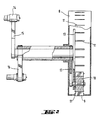
- each layer of the mat is stretched from the orifices (2) of a die (1) a multiplicity of fused glass fillets in the form of a sheet of filaments continuous (3), then the filaments are coated with a sizing composition protecting in particular from abrasion, using a sizing device (4) before to gather the filaments into threads (5).
- the wires after passing over a wheel guide (6) and a idler wheel (7) are driven by the drawing wheel (8) in rotation (symbolized by a simple arrow) then ejected from this wheel in one point which moves around the periphery of the wheel in an arc (beat movement symbolized by a double arrow).
- the ejection is operated by means of the fins (9) of the projection wheel (10) (called also “winged wheel”) located inside the drawing wheel and moving inside said wheel, the fins passing through slots (11) on the surface of the stretching wheel.
- the wires are thrown tangentially to the drawing wheel and following the flapping movement of the projection wheel.
- the projected wires are thus distributed on a conveyor (12) moving transversely relative to the direction of the projected wires.
- the stretching wheel (used to stretch and drive the wires) is generally fitted with an independent movable rear plate (13) on which the projection wheel (10), the servomotor (14) driving the back plate and thus the projection wheel in a flapping motion.
- the actuator can be mounted "on" the axis of the drawing wheel (the movement being able possibly be transmitted by simple mechanical means, in particular a rod of simple form (15)) just like the first motor being used to drive the stretching wheel (the movement can possibly be transmitted by a simple means such as a belt (16)) and, if necessary, the projection wheel in rotation (the rotational movement then being transmitted to the latter wheel by mechanical means such as a belt (17) and thus being synchronized with the rotary movement of the drawing wheel).
- the device according to the invention can also include a module and / or a programmable control system for the servomotors, and may include one or more other selected members among those usually used in mast production devices.
- a module and / or a programmable control system for the servomotors may include one or more other selected members among those usually used in mast production devices.
- at least two offset dies are used and arranged on either side of the conveyor, each die being associated with a stretching system and its own projection member, each projection being controlled by an independent servomotor.
- the masts according to the invention can be used to produce composites.
- Several masts can in particular be stacked, with the same orientation or different orientations (in particular by crossing them at 90 °), and be preformed to give reinforcements to the shape of the part to be molded.
- the composites produced include at least one mat according to the invention and minus organic matter.
- Composites made from mats according to the invention have properties superior to the composites produced at from isotropic mats or anisotropic mats with a low level of oriented wires, in at least one direction.
- the tensile strength of the composite measured in any direction in the plane of the composite is approximately 145 MPa.
- the bending breaking stress of the composite measured in any direction in the plane of the composite is 300 MPa.
- the notched Charpy impact strength of the composite measured in any direction in the plane of the composite is 85 kJ / m 2 .
- the procedure is as in the reference example by replacing the four isotropic mats with four mats of the same grammage (450 g / m 2 ) each having 80% by weight of wires oriented in a preferential transverse direction, the mats being stacked so as to have the same preferential orientation within the composite.
- the tensile strength of the composite measured in the preferential direction of orientation of the wires is approximately 215 MPa and that measured in the direction perpendicular to the preferred direction (in the composite plane) is approximately 45 MPa.
- the bending breaking stress of the composite measured in the preferred direction of orientation of the wires is approximately 530 MPa and that measured in the direction perpendicular to the preferred direction (in the composite plane) is approximately 105 MPa.
- the notched Charpy impact resistance measured in the direction of preferential orientation of the wires is approximately 205 kJ / m 2 and that measured in the direction perpendicular to the preferred direction (in the plane of the composite) is 40 kJ / m 2 about.
- Example 2 We proceed as in Example 1 by rotating 90 ° to two of the masts in the plane of the composite.
- the tensile strength of the composite measured in the preferential direction of orientation of the wires of two of the masts or in the perpendicular direction (in the plane of the composite) to this direction preferred is approximately 160 MPa.
- the bending breaking stress of the composite measured in the preferential direction of orientation of the wires of two of the masts or in the perpendicular direction (in the plane of the composite) to this direction preferred is approximately 320 MPa.
- the non-notched Charpy impact resistance measured in the preferred direction of orientation of the wires of two of the masts or in the direction perpendicular (in the plane of the composite) to this preferred direction is approximately 110 kJ / m 2 .
- the masts according to the invention can be used to reinforce bumpers of motor vehicles, rear shelves of motor vehicles, etc.
Landscapes
- Engineering & Computer Science (AREA)
- Textile Engineering (AREA)
- Chemical & Material Sciences (AREA)
- Inorganic Chemistry (AREA)
- Nonwoven Fabrics (AREA)
- Laminated Bodies (AREA)
- Yarns And Mechanical Finishing Of Yarns Or Ropes (AREA)
- Woven Fabrics (AREA)
- Joining Of Glass To Other Materials (AREA)
- Glass Compositions (AREA)
- Reinforced Plastic Materials (AREA)
- Medicines Containing Plant Substances (AREA)
Applications Claiming Priority (3)
| Application Number | Priority Date | Filing Date | Title |
|---|---|---|---|
| FR9610888A FR2753207B1 (fr) | 1996-09-06 | 1996-09-06 | Mat anisotrope de fils de verre continus et procede de fabrication |
| FR9610888 | 1996-09-06 | ||
| PCT/FR1997/001556 WO1998010131A1 (fr) | 1996-09-06 | 1997-09-04 | Mat anisotrope de fils de verre continus et procede de fabrication |
Publications (2)
| Publication Number | Publication Date |
|---|---|
| EP0859882A1 EP0859882A1 (fr) | 1998-08-26 |
| EP0859882B1 true EP0859882B1 (fr) | 2002-05-29 |
Family
ID=9495513
Family Applications (1)
| Application Number | Title | Priority Date | Filing Date |
|---|---|---|---|
| EP97938978A Expired - Lifetime EP0859882B1 (fr) | 1996-09-06 | 1997-09-04 | Mat anisotrope de fils de verre continus et procede de fabrication |
Country Status (15)
| Country | Link |
|---|---|
| EP (1) | EP0859882B1 (da) |
| JP (1) | JP4114954B2 (da) |
| KR (1) | KR20000064327A (da) |
| AT (1) | ATE218172T1 (da) |
| AU (1) | AU731107C (da) |
| BR (1) | BR9706710A (da) |
| CA (1) | CA2236841A1 (da) |
| DE (1) | DE69712862T2 (da) |
| DK (1) | DK0859882T3 (da) |
| ES (1) | ES2176775T3 (da) |
| FR (1) | FR2753207B1 (da) |
| NO (1) | NO981972L (da) |
| NZ (1) | NZ330156A (da) |
| PT (1) | PT859882E (da) |
| WO (1) | WO1998010131A1 (da) |
Families Citing this family (2)
| Publication number | Priority date | Publication date | Assignee | Title |
|---|---|---|---|---|
| US20060135017A1 (en) * | 2004-12-16 | 2006-06-22 | Jeng Lin | Continuous filament mat and method of making |
| NL1037958C2 (en) * | 2010-05-12 | 2011-11-15 | Willem Frans Mast | A method and a system for producing a mat of fibrous material. |
Family Cites Families (4)
| Publication number | Priority date | Publication date | Assignee | Title |
|---|---|---|---|---|
| US3265481A (en) * | 1962-10-18 | 1966-08-09 | Owens Corning Fiberglass Corp | Apparatus for delivering multifilament strands |
| GB1233151A (da) * | 1969-05-20 | 1971-05-26 | ||
| US4158557A (en) * | 1978-04-26 | 1979-06-19 | Ppg Industries, Inc. | Method and apparatus for forming fiber mat |
| CA2028423C (en) * | 1989-11-13 | 1994-08-16 | William L. Schaefer | Programmably controlled fiber glass strand feeders and improved methods for making glass fiber mats |
-
1996
- 1996-09-06 FR FR9610888A patent/FR2753207B1/fr not_active Expired - Fee Related
-
1997
- 1997-09-04 EP EP97938978A patent/EP0859882B1/fr not_active Expired - Lifetime
- 1997-09-04 AU AU41224/97A patent/AU731107C/en not_active Ceased
- 1997-09-04 KR KR1019980703285A patent/KR20000064327A/ko not_active Ceased
- 1997-09-04 NZ NZ330156A patent/NZ330156A/xx unknown
- 1997-09-04 ES ES97938978T patent/ES2176775T3/es not_active Expired - Lifetime
- 1997-09-04 WO PCT/FR1997/001556 patent/WO1998010131A1/fr not_active Ceased
- 1997-09-04 BR BR9706710A patent/BR9706710A/pt not_active Application Discontinuation
- 1997-09-04 PT PT97938978T patent/PT859882E/pt unknown
- 1997-09-04 DE DE69712862T patent/DE69712862T2/de not_active Expired - Lifetime
- 1997-09-04 JP JP51230598A patent/JP4114954B2/ja not_active Expired - Lifetime
- 1997-09-04 DK DK97938978T patent/DK0859882T3/da active
- 1997-09-04 CA CA002236841A patent/CA2236841A1/fr not_active Abandoned
- 1997-09-04 AT AT97938978T patent/ATE218172T1/de not_active IP Right Cessation
-
1998
- 1998-04-30 NO NO981972A patent/NO981972L/no not_active Application Discontinuation
Also Published As
| Publication number | Publication date |
|---|---|
| NO981972D0 (no) | 1998-04-30 |
| ATE218172T1 (de) | 2002-06-15 |
| AU4122497A (en) | 1998-03-26 |
| FR2753207B1 (fr) | 1998-10-16 |
| CA2236841A1 (fr) | 1998-03-12 |
| AU731107B2 (en) | 2001-03-22 |
| WO1998010131A1 (fr) | 1998-03-12 |
| EP0859882A1 (fr) | 1998-08-26 |
| AU731107C (en) | 2001-12-06 |
| NZ330156A (en) | 2000-01-28 |
| JP4114954B2 (ja) | 2008-07-09 |
| NO981972L (no) | 1998-04-30 |
| BR9706710A (pt) | 1999-07-20 |
| ES2176775T3 (es) | 2002-12-01 |
| FR2753207A1 (fr) | 1998-03-13 |
| PT859882E (pt) | 2002-10-31 |
| DE69712862D1 (de) | 2002-07-04 |
| JPH11514711A (ja) | 1999-12-14 |
| DK0859882T3 (da) | 2002-09-16 |
| DE69712862T2 (de) | 2003-01-09 |
| KR20000064327A (ko) | 2000-11-06 |
Similar Documents
| Publication | Publication Date | Title |
|---|---|---|
| EP0270411B1 (fr) | Structure textile permettant la réalisation d'articles stratifiés composites par moulage par injection | |
| EP1373621B1 (fr) | Procede et dispositif de fabrication d'une plaque composite a renfort fibreux multiaxial | |
| FR2463221A1 (fr) | Feuilles thermoplastiques armees de fibres de verre a resistance elevee et leur procede de fabrication | |
| EP3426452B1 (fr) | Procédé de réalisation de préformes avec application d'un liant sur fibre sèche, et machine correspondante | |
| EP0724949B1 (fr) | Procédé et dispositif pour appliquer un fil sur un support | |
| EP1226298B1 (fr) | Procede et dispositif de fabrication de plaques composites | |
| EP0402443B1 (fr) | Structures textiles, utiles comme renforts dans la fabrication de materiaux composites, et fils techniques pour de telles structures | |
| EP0859882B1 (fr) | Mat anisotrope de fils de verre continus et procede de fabrication | |
| EP1893398B1 (fr) | Procede de realisation d'un renfort pour materiau composite a profil de resistance variable, renfort obtenu | |
| FR3053912A1 (fr) | Procede d’obtention d’une piece profilee courbe en matiere composite thermoplastique et installation de mise en œuvre de ce procede | |
| EP1497104A2 (fr) | Procede de fabrication d'un nouveau materiau compose de faisceaux de fibres naturelles pre impregnees de resine organique et se presentant sous forme de fil ou de ruban | |
| EP3678826A1 (fr) | Procédé de réalisation de préformés avec application d'un liant sur fibre sèche formée de plusieurs fibres initiales | |
| EP0687315B1 (fr) | Tissu tridimensionnel multiaxial et son procede de fabrication | |
| EP3315296A1 (fr) | Procédé perfectionné d'obtention d'une pièce profilée courbe en matière composite thermoplastique et installation de mise en uvre de ce procédé | |
| WO2020249898A1 (fr) | Module de dépose pour tête de dépose de tronçons de bande de fibres pour la réalisation de pièce en matériaux composites, tête de dépose, robot de dépose, et procédé de dépose | |
| EP1144745B1 (fr) | Procede de fabrication d'un mat et produits obtenus | |
| FR2584341A1 (fr) | Procede de fabrication d'une peau bobinee en materiau composite renforce de fibres, en particulier pour structures sandwiches | |
| FR3097159A1 (fr) | Module de découpe pour tête de dépose de tronçons de bande de fibres pour la réalisation de pièce en matériaux composites, tête de dépose, robot de dépose et procédé de découpe et procédé de dépose. | |
| FR2671308A1 (fr) | Procede et dispositif pour appliquer plusieurs fils sur un support a l'aide de dents flexibles; nappe obtenue et article comportant au moins une nappe : enveloppe pneumatique. | |
| FR3097156A1 (fr) | Module d’alimentation pour tête de dépose de tronçons de bande de fibres pour la réalisation de pièce en matériaux composites, tête de dépose, robot de dépose et procédé d’alimentation et procédé de dépose. | |
| WO2020128369A1 (fr) | Corde composite | |
| WO2019129795A1 (fr) | Procédé de fabrication d'un semi-produit pour une pièce de véhicule automobile | |
| FR2960178A1 (fr) | Procede de depose de fibres pour l'obtention d'une structure raidie et structure ainsi obtenue |
Legal Events
| Date | Code | Title | Description |
|---|---|---|---|
| PUAI | Public reference made under article 153(3) epc to a published international application that has entered the european phase |
Free format text: ORIGINAL CODE: 0009012 |
|
| 17P | Request for examination filed |
Effective date: 19980328 |
|
| AK | Designated contracting states |
Kind code of ref document: A1 Designated state(s): AT BE CH DE DK ES FI FR GB IE IT LI LU NL PT SE |
|
| 17Q | First examination report despatched |
Effective date: 20001110 |
|
| GRAG | Despatch of communication of intention to grant |
Free format text: ORIGINAL CODE: EPIDOS AGRA |
|
| GRAG | Despatch of communication of intention to grant |
Free format text: ORIGINAL CODE: EPIDOS AGRA |
|
| GRAH | Despatch of communication of intention to grant a patent |
Free format text: ORIGINAL CODE: EPIDOS IGRA |
|
| RAP1 | Party data changed (applicant data changed or rights of an application transferred) |
Owner name: SAINT-GOBAIN VETROTEX FRANCE |
|
| GRAH | Despatch of communication of intention to grant a patent |
Free format text: ORIGINAL CODE: EPIDOS IGRA |
|
| GRAA | (expected) grant |
Free format text: ORIGINAL CODE: 0009210 |
|
| AK | Designated contracting states |
Kind code of ref document: B1 Designated state(s): AT BE CH DE DK ES FI FR GB IE IT LI LU NL PT SE |
|
| REF | Corresponds to: |
Ref document number: 218172 Country of ref document: AT Date of ref document: 20020615 Kind code of ref document: T |
|
| REG | Reference to a national code |
Ref country code: GB Ref legal event code: FG4D Free format text: NOT ENGLISH |
|
| REG | Reference to a national code |
Ref country code: CH Ref legal event code: EP |
|
| REG | Reference to a national code |
Ref country code: IE Ref legal event code: FG4D Free format text: FRENCH |
|
| REF | Corresponds to: |
Ref document number: 69712862 Country of ref document: DE Date of ref document: 20020704 |
|
| REG | Reference to a national code |
Ref country code: CH Ref legal event code: NV Representative=s name: KIRKER & CIE SA |
|
| REG | Reference to a national code |
Ref country code: DK Ref legal event code: T3 |
|
| GBT | Gb: translation of ep patent filed (gb section 77(6)(a)/1977) |
Effective date: 20020829 |
|
| REG | Reference to a national code |
Ref country code: PT Ref legal event code: SC4A Free format text: AVAILABILITY OF NATIONAL TRANSLATION Effective date: 20020821 |
|
| REG | Reference to a national code |
Ref country code: ES Ref legal event code: FG2A Ref document number: 2176775 Country of ref document: ES Kind code of ref document: T3 |
|
| PLBE | No opposition filed within time limit |
Free format text: ORIGINAL CODE: 0009261 |
|
| STAA | Information on the status of an ep patent application or granted ep patent |
Free format text: STATUS: NO OPPOSITION FILED WITHIN TIME LIMIT |
|
| 26N | No opposition filed |
Effective date: 20030303 |
|
| PGFP | Annual fee paid to national office [announced via postgrant information from national office to epo] |
Ref country code: PT Payment date: 20030827 Year of fee payment: 7 |
|
| PGFP | Annual fee paid to national office [announced via postgrant information from national office to epo] |
Ref country code: SE Payment date: 20030904 Year of fee payment: 7 |
|
| PGFP | Annual fee paid to national office [announced via postgrant information from national office to epo] |
Ref country code: LU Payment date: 20030909 Year of fee payment: 7 |
|
| PGFP | Annual fee paid to national office [announced via postgrant information from national office to epo] |
Ref country code: AT Payment date: 20030911 Year of fee payment: 7 |
|
| PGFP | Annual fee paid to national office [announced via postgrant information from national office to epo] |
Ref country code: FI Payment date: 20030912 Year of fee payment: 7 |
|
| PGFP | Annual fee paid to national office [announced via postgrant information from national office to epo] |
Ref country code: DK Payment date: 20030915 Year of fee payment: 7 |
|
| PGFP | Annual fee paid to national office [announced via postgrant information from national office to epo] |
Ref country code: CH Payment date: 20030918 Year of fee payment: 7 |
|
| PGFP | Annual fee paid to national office [announced via postgrant information from national office to epo] |
Ref country code: NL Payment date: 20030922 Year of fee payment: 7 |
|
| PGFP | Annual fee paid to national office [announced via postgrant information from national office to epo] |
Ref country code: IE Payment date: 20030923 Year of fee payment: 7 |
|
| PGFP | Annual fee paid to national office [announced via postgrant information from national office to epo] |
Ref country code: BE Payment date: 20031010 Year of fee payment: 7 |
|
| PGFP | Annual fee paid to national office [announced via postgrant information from national office to epo] |
Ref country code: ES Payment date: 20031021 Year of fee payment: 7 |
|
| PG25 | Lapsed in a contracting state [announced via postgrant information from national office to epo] |
Ref country code: LU Free format text: LAPSE BECAUSE OF NON-PAYMENT OF DUE FEES Effective date: 20040904 Ref country code: FI Free format text: LAPSE BECAUSE OF NON-PAYMENT OF DUE FEES Effective date: 20040904 Ref country code: AT Free format text: LAPSE BECAUSE OF NON-PAYMENT OF DUE FEES Effective date: 20040904 |
|
| PG25 | Lapsed in a contracting state [announced via postgrant information from national office to epo] |
Ref country code: SE Free format text: LAPSE BECAUSE OF NON-PAYMENT OF DUE FEES Effective date: 20040905 |
|
| PG25 | Lapsed in a contracting state [announced via postgrant information from national office to epo] |
Ref country code: IE Free format text: LAPSE BECAUSE OF NON-PAYMENT OF DUE FEES Effective date: 20040906 Ref country code: ES Free format text: LAPSE BECAUSE OF NON-PAYMENT OF DUE FEES Effective date: 20040906 |
|
| PG25 | Lapsed in a contracting state [announced via postgrant information from national office to epo] |
Ref country code: LI Free format text: LAPSE BECAUSE OF NON-PAYMENT OF DUE FEES Effective date: 20040930 Ref country code: DK Free format text: LAPSE BECAUSE OF NON-PAYMENT OF DUE FEES Effective date: 20040930 Ref country code: CH Free format text: LAPSE BECAUSE OF NON-PAYMENT OF DUE FEES Effective date: 20040930 Ref country code: BE Free format text: LAPSE BECAUSE OF NON-PAYMENT OF DUE FEES Effective date: 20040930 |
|
| PG25 | Lapsed in a contracting state [announced via postgrant information from national office to epo] |
Ref country code: PT Free format text: LAPSE BECAUSE OF NON-PAYMENT OF DUE FEES Effective date: 20050304 |
|
| BERE | Be: lapsed |
Owner name: *SAINT-GOBAIN VETROTEX FRANCE Effective date: 20040930 |
|
| PG25 | Lapsed in a contracting state [announced via postgrant information from national office to epo] |
Ref country code: NL Free format text: LAPSE BECAUSE OF NON-PAYMENT OF DUE FEES Effective date: 20050401 |
|
| EUG | Se: european patent has lapsed | ||
| REG | Reference to a national code |
Ref country code: CH Ref legal event code: PL |
|
| REG | Reference to a national code |
Ref country code: PT Ref legal event code: MM4A Free format text: LAPSE DUE TO NON-PAYMENT OF FEES Effective date: 20050304 |
|
| NLV4 | Nl: lapsed or anulled due to non-payment of the annual fee |
Effective date: 20050401 |
|
| REG | Reference to a national code |
Ref country code: IE Ref legal event code: MM4A |
|
| REG | Reference to a national code |
Ref country code: DK Ref legal event code: EBP |
|
| REG | Reference to a national code |
Ref country code: ES Ref legal event code: FD2A Effective date: 20040906 |
|
| BERE | Be: lapsed |
Owner name: *SAINT-GOBAIN VETROTEX FRANCE Effective date: 20040930 |
|
| REG | Reference to a national code |
Ref country code: FR Ref legal event code: PLFP Year of fee payment: 20 |
|
| PGFP | Annual fee paid to national office [announced via postgrant information from national office to epo] |
Ref country code: GB Payment date: 20160927 Year of fee payment: 20 |
|
| PGFP | Annual fee paid to national office [announced via postgrant information from national office to epo] |
Ref country code: FR Payment date: 20160926 Year of fee payment: 20 |
|
| PGFP | Annual fee paid to national office [announced via postgrant information from national office to epo] |
Ref country code: DE Payment date: 20160928 Year of fee payment: 20 |
|
| PGFP | Annual fee paid to national office [announced via postgrant information from national office to epo] |
Ref country code: IT Payment date: 20160923 Year of fee payment: 20 |
|
| REG | Reference to a national code |
Ref country code: DE Ref legal event code: R071 Ref document number: 69712862 Country of ref document: DE |
|
| REG | Reference to a national code |
Ref country code: GB Ref legal event code: PE20 Expiry date: 20170903 |
|
| PG25 | Lapsed in a contracting state [announced via postgrant information from national office to epo] |
Ref country code: GB Free format text: LAPSE BECAUSE OF EXPIRATION OF PROTECTION Effective date: 20170903 |