EP0859086A2 - Cylindrical brush for a sweeping machine - Google Patents
Cylindrical brush for a sweeping machine Download PDFInfo
- Publication number
- EP0859086A2 EP0859086A2 EP98301149A EP98301149A EP0859086A2 EP 0859086 A2 EP0859086 A2 EP 0859086A2 EP 98301149 A EP98301149 A EP 98301149A EP 98301149 A EP98301149 A EP 98301149A EP 0859086 A2 EP0859086 A2 EP 0859086A2
- Authority
- EP
- European Patent Office
- Prior art keywords
- brush
- sweeping
- spiral
- debris
- cylindrical body
- Prior art date
- Legal status (The legal status is an assumption and is not a legal conclusion. Google has not performed a legal analysis and makes no representation as to the accuracy of the status listed.)
- Granted
Links
Images

Classifications
-
- A—HUMAN NECESSITIES
- A46—BRUSHWARE
- A46B—BRUSHES
- A46B13/00—Brushes with driven brush bodies or carriers
- A46B13/001—Cylindrical or annular brush bodies
-
- E—FIXED CONSTRUCTIONS
- E01—CONSTRUCTION OF ROADS, RAILWAYS, OR BRIDGES
- E01H—STREET CLEANING; CLEANING OF PERMANENT WAYS; CLEANING BEACHES; DISPERSING OR PREVENTING FOG IN GENERAL CLEANING STREET OR RAILWAY FURNITURE OR TUNNEL WALLS
- E01H1/00—Removing undesirable matter from roads or like surfaces, with or without moistening of the surface
- E01H1/02—Brushing apparatus, e.g. with auxiliary instruments for mechanically loosening dirt
- E01H1/04—Brushing apparatus, e.g. with auxiliary instruments for mechanically loosening dirt taking- up the sweepings, e.g. for collecting, for loading
- E01H1/045—Brushing apparatus, e.g. with auxiliary instruments for mechanically loosening dirt taking- up the sweepings, e.g. for collecting, for loading the loading means being a rotating brush with horizontal axis
Definitions
- the present invention relates to the field of sweeping machines. More particularly, this invention relates to a brush for a sweeping machine for picking up various types of debris from a surface being swept.
- sweeping machines for removing various types of debris from a surface, such as the ground, a floor or a parking lot.
- Many of these sweeping machines use a rotating cylindrical brush to contact the surface being swept.
- the rotating cylindrical brush is used to lift various types of debris from the floor or surface and throw it into a debris hopper located near the rotating cylindrical brush.
- the machine moves the rotating cylindrical brush over the surface being swept.
- the rotational velocity of the cylindrical brush produces a velocity at the ends of the brush that differs from the velocity of the machine as it moves over the surface being swept.
- the brush can be rotated in either direction.
- sweepers Two types of sweepers are forward throw sweeper and indirect throw sweepers.
- Forward throw sweepers use a brush rotated backward with respect to the travel of the sweeping.
- the debris is thrown forward and collected in a container which is forward of the brush.
- Indirect throw or over-the-top sweepers use a brush rotated in either direction with a debris container located for collection of the debris.
- Sweeping machines are used in a variety of environments. For example, some sweeping machines remove debris from roads and streets. Others are used to remove debris from parking lots and others are used to remove debris from factory floors. In short, there are many applications for sweeping machines. Sweeping machines also remove different types of debris. Certain brush designs can be employed to enhance a sweeping machine's ability to pick up or remove certain types of debris.
- full fill or high density there are several types of brush fill patterns which are customarily used.
- One predominant type of brush fill pattern is termed full fill or high density.
- a full fill type brush the bristles or other sweeping material are closely packed together or in a highly dense configuration.
- the bristles or other sweeping material of a full fill brush can be placed in almost any type of pattern to form a full fill type brush.
- the full fill brush presents a substantially solid mass of bristles or other sweeping material.
- Full fill type brushes are generally effective in removing relatively thin layers of fine material from surfaces being swept.
- Fine materials also referred to as fines, include very fine particles, such as sands which are used in foundries for making molds, cement dust, and sand found in parking lots or in streets.
- a second predominant type of brush fill pattern has spaces between rows of bristles or other sweeping material.
- This second type of brush has a number of variations.
- a brush called a double row brush has two rows of closely spaced bristles or other sweeping material. This is called a double row. There is a larger space between each double row of bristles or other sweeping material.
- This second type of brush fill pattern is better for removing bulkier debris or deeper layers of fine material.
- the second predominant type of brush fill pattern is formed by placing the bristles or other sweeping material in one of several patterns.
- One pattern is to place the bristles or other sweeping material in straight lines along the brush tube.
- the straight lines are substantially parallel to the axis of the brush tube.
- Brushes with straight line pattern of bristles or other sweeping material and spaces between the straight bristles or other sweeping material cause a brush to bounce or jump excessively because as the brush rotates, the brush alternates between having all the bristles or other sweeping material in one row of the brush in contact with the surface being swept and no bristles in contact with the surface being swept.
- the result of brush bounce is chatter lines of fine debris being left on the surface that has been swept. Brush bounce may also cause vibration of the sweeping machine.
- the rows of bristles are placed in spiral patterns along the surface of the brush tube.
- the spiral pattern has a number of spiral tufts placed in a pattern with spaces between the spiral pattern of tufts of sweeping material.
- the amount of brush material in contact with the surface being swept is substantially constant as the brush rotates so as to minimize the amount of brush bounce.
- Spiral pattern brushes also have a problem. Debris or fines may travel along the length of the brush.
- the spiral pattern having spaces between the spirals acts as an auger that may move the debris or fines in one direction along the surface of the brush. This can be a disadvantage since some debris or fines may be augured out at one end of the brush.
- herringbone pattern may also be termed a chevron pattern or may be termed as alternating spirals. These herringbone patterns prevent the migration of debris and material being swept from being augured down the length of the brush.
- the herringbone pattern allows material being swept to only travel to the point where the spiral changes directions. As a result, these types of brushes are more effective at sweeping up certain types of debris and preventing the auguring along the entire length of the brush during rotation.
- Herringbone type brushes do auger debris a certain length.
- the herringbone patterns can be thought of as using one full chevron or a multiple of one full chevron.
- One full chevron will have a first spiral in a first direction and a second spiral in a second direction.
- Brushes which do use the herringbone patterns auger debris along the length of the spiral until the spiral changes directions.
- the problem with a pattern of brush which has a number of full chevrons or the same number of different direction spirals is that at both ends of the cylindrical brush, the debris or material being swept will be either augured outward or inward from the end of the cylindrical brush.
- the direction of auguring is dependent on the orientation of the chevrons with respect to the rotational direction of the brush.
- the bristles or brush material forming the brush can take a set. In other words, like a push broom, the bristles or brush material can bend over and become less effective.
- regular maintenance requires that the brush be switched or flipped end to end to change the orientation of the chevrons and prevent the bristles or other sweeping material or brush fill material from taking a set in one direction. Flipping the brush end to end changes the direction of the force on the tufts or bristles of the brush.
- the chevrons of the cylindrical brush will auger debris toward both ends of the brush which increases the possibility of trailing. Trailing is where some amount of debris or fines is left at the ends of the brush after the sweeping machine has passed.
- Auguring of fines or other debris is troublesome when you consider that many times much of the debris is located on one end of the brush. For example, in streets it has been found that the vast majority of the debris and fines are located on one end of the brush, mainly near the curb and in the gutter. In this instance, there is a need for a cylindrical brush for use on a sweeping machine that will auger the fines or other debris inward toward the center of the brush while it is rotating no matter what orientation of the brush fill pattern of the cylindrical brush. There is also a need for a cylindrical brush that will prevent the material being swept from travelling along the entire length of the brush.
- a brush that will auger the debris or fines being swept in toward the center of the brush from a selected or desired side of a sweeping machine even when the brush is flipped end- for-end and the brush fill material is re-orientated. For example, it is necessary to have a brush that will auger the material being swept inward despite whether it is in a first orientation or whether it has been flipped end-to-end to a second orientation for maintenance purposes.
- a sweeping brush that will consistently pick up varying types of debris on a variety of surfaces and one that limits axial migration of debris toward the ends of a rotating cylindrical brush.
- a brush that minimizes trailing.
- a sweeping machine that is smooth and stable during its operation.
- the present invention provides a brush for a sweeping machine adapted to remove debris from a surface, said brush comprising:
- the present invention provides a brush for sweeping a surface to remove debris from said surface, said brush comprising:
- the present invention provides a cylindrical brush for a sweeping machine comprising:
- a rotatable cylindrical brush for a sweeping machine includes a tube having sweeping material or brush fill material attached to the core or brush tube.
- the sweeping material extends radially outward from the surface of said core or brush tube.
- the sweeping material forms a plurality rows.
- a row has a first spiral section in a first direction located on one end of the core and a third spiral section in a first direction located on the other end of the core.
- a second spiral section spiralling in a second direction is located intermediate the first and third spiral sections at the ends of the core or brush tube.
- the rows may be spaced from one another so that the space forms a similar pattern.
- the brush can also be thought of as having a plurality of sections having a plurality of rows.
- the brush includes preferably n + 1 spiral sections in a first direction, and n spirals in a second direction.
- the rows on the brush can also be thought of as forming a "V" or chevron pattern with an additional spiral attached to the end of a full “V” or chevron.
- the spiral sections at the end of the brush are oriented so that one selected or desired end of the brush augers debris in toward the middle of the brush.
- the debris is restricted in its travel along the length of the cylindrical body of the brush.
- the debris is also moved from the desired or selected end of the brush for effective sweeping with minimized trailing or debris at the desired or selected end of the cylindrical brush.
- the brush can also be flipped end-to-end thereby re-orientating the brush fill pattern and the bristles with respect to the surface being swept. After being flipped, the brush will still auger debris inward from a desired or selected side of the sweeping machine.
- a sweeping machine equipped with the cylindrical brush mentioned above picks up or sweeps substantially all types of debris.
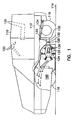
- FIG. 1 is a side view of the sweeping machine.
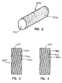
- FIG. 2 is a front view of a full fill type of cylindrical brush for a sweeping machine.
- FIG. 3 is a front view of a spiral cylindrical brush for the sweeping machine.
- FIG. 4 is a front view of a cylindrical brush having a herringbone pattern.
- FIG. 5 is a front view of a cylindrical brush for the sweeping machine having a double herringbone pattern.
- FIG. 6 is a top schematic view of a cylindrical brush having a pattern with a herringbone plus an added spiral pattern and attached the sweeping machine.
- FIG. 7 is a front view of a cylindrical brush for the sweeping machine having a pattern with a herringbone plus an added spiral pattern.
- FIG. 1 is a side view of a forward throw type sweeping machine which uses a preferred embodiment of the present invention. It should be noted that the brush can be used on any type of sweeping machine and that the one shown in FIG. 1 is for the purpose of illustration.
- the sweeper 110 has a frame 112 and is supported on a surface to be swept 114 by two free rolling front wheels 116 (only one shown) and one steerable, powered rear wheel 118. Provisions for a driver are indicated generally by a seat 120 and a steering wheel 122. Other conventional controls are also provided, but are not shown.
- a cylindrical sweeping brush 124 is mounted in a conventional manner and extends across most of the transverse width of the sweeping machine. It is supported between two brush arms 126 (only one shown) which are attached in pivotal manner to the sides of the frame 112 at two transversely aligned points 128 (only one shown).
- a cross shaft 130 joins the two brush arms 126 together so that both ends of brush 124 are maintained in alignment.
- a lift arm 132 is welded or otherwise attached to one brush arm, and is pivotally connected at its upper end to a cable assembly 133. This connects to a hydraulic cylinder 134 which is used to raise the brush 124 off the surface 114 for transport, or lowered to its working position as shown in FIG. 1. In working position, cable assembly 133 may be slack.
- the engagement of brush 124 with surface 14 may be controlled by an adjustable down stop (not shown).
- an adjustable down stop (not shown). This may be made in any one of several conventional ways. Commonly such a stop is a heavy screw bearing against a lug welded to cross shaft 130. A knob on the opposite end of the screw will be accessible to the driver. By turning the knob, the driver or operator can set the brush height for a desired floor contact, or pattern, and can re-set it when needed as the brush wears.
- Brush 124 is rotated by a hydraulic motor. This motor is supplied by hoses 136.
- the opposite brush arm 126 (not shown) carries an idler bearing assembly which rotatably supports the opposite end of brush 124.
- the sweeper 110 also includes a planar side sweep brush 610 (shown in Fig.
- the side sweep brush 610 places debris or fines in front of the cylindrical brush 124 so that it can be swept and placed into the hopper 168 of the sweeping machine.
- the side sweep brush 610 can also be positioned to increase the effective sweep width of the sweeping machine beyond the path of the cylindrical sweeping brush 124.
- FIGs. 2-5 are front views of conventional prior art brushes that have been used on sweeping machines 110.
- the brush 200 shown in FIG. 2 has been removed from the sweeping machine 110 so that the pattern can be easily viewed.
- the brush 200 is a cylindrical sweeping brush and further comprises a core or brush tube 210.
- the core 210 is a member to which sweeping material 220, such as tufts of bristles, can be attached.
- the core or brush tube 210 is also capable of being rotated.
- the core of any of the brushes described could be a tube, a hollow cylinder, a solid cylinder, entwined metal members or the like. It should be noted here that brush 200 shown in FIG. 2 is populated by bristles or sweeping material with full-length bristles.
- Sweeping fill material 220 such as bristles
- the brush fill material 220 can also be made of brush wire, or fill materials of a plant or animal origin.
- the cross sectional size and shape and the length of the bristles can also be varied to tailor the cylindrical brush 200 for a particular purpose.
- a full fill type brush 200 the bristles or other sweeping fill material 220 are closely packed together or in a highly dense configuration.
- the full fill type brush 200 has no discernable pattern.
- the bristles or other sweeping material 220 of a full fill brush 200 are so closely packed that they can be placed in almost any type of pattern to form a full fill type brush.
- the full fill brush presents a solid mass of bristles or other sweeping material.
- Full fill type brushes 200 are effective in removing relatively thin layers of fine material from surfaces being swept.
- FIG. 3 we see another conventional brush which is a spiral type cylindrical brush 300.
- the bristles or sweeping fill material 220 is placed in spiral pattern along the surface of the core or brush tube 210.
- the spiral pattern has a number of spiral rows 310 of tufts of brush fill material 220 with alternating spiral spaces 320 between the spiral rows of sweeping material.
- the amount of bristle or brush material in contact with the surface being swept is substantially constant as the brush rotates so as to minimize the amount of brush bounce.
- debris or fines may travel along the length of the brush 300.
- the spiral rows 310 of the brush material 220 and the spiral spaces 320 in the pattern act like an auger that may move the debris or fines in one direction along the surface of the brush 300.
- FIGS. 4 and 5 show brushes that have a herringbone pattern and a double herringbone pattern, respectively.
- Brush 400 has brush fill material 220 attached to a brush tube or core 210 to form rows 410 in a herringbone pattern.
- the pattern also features spaces 420 between rows which are also in a herringbone pattern.
- Each row 410 can be made of a one or more rows of sweeping fill material 220. In other words, two rows could be packed closely together to form a thicker herringbone pattern row 410.
- the herringbone pattern can also be thought of as chevron pattern or a "V"-shape pattern.
- the pattern that the row 410 makes is characterized in that it has a first spiral in one direction attached to a second spiral in a second direction.
- the first direction may be a counterclockwise spiral like a right hand thread.
- the second direction may be a clockwise spiral like a left hand thread.
- the herringbone pattern is characterized in that there are an equal number of spiral sections of the brush in a first direction and an equal number of spirals on the brush in a second direction.
- the brush 400 has one section of the brush 400 or one end, which has a spiral in a first direction and the other end of the brush has a second spiral in a second direction.
- the herringbone pattern is advantageous in that when the brush 400 is rotated in a particular direction, the debris or fines will be augured in toward the center of the brush 400.
- Herringbone patterns are used to prevent the transport of debris or fines or material being swept along the entire length of the brush 400. Fines or materials being swept can be transferred or moved across the entire length of the spiral brush.
- the herringbone pattern acts to break up this transfer movement of debris or fines.
- the problem with the herringbone brush is that a regular maintenance item for most brushes is that they must be flipped end-to-end on a sweeper 110 periodically to re-orientate the brush fill material.
- the end result is that the force on the brush fill material is in the opposite direction after the brush has been flipped. This prevents the brush fill material from taking a set in one direction.
- the direction which the debris or fines is augured is changed so that the debris and fines are augured out toward the ends of the brush 400.
- FIG. 5 shows a double herringbone brush 500.
- the row 510 and brush material 220 is in a pattern with two herringbones connected end-to-end.
- the herringbones can also be thought of as "V's" or chevrons.
- the brush 500 can be broken into four sections. In the first and second sections the spiral is in a first direction. In the third and fourth sections of the brush 500, the spiral is in a second direction. Just like the brush 400, the brush 500 has the same number of spirals in the first direction as in the second direction.
- the problems associated with the single herringbone brush 400 are the same as those associated with the double herringbone brush 500.
- One of the problems is that when the brush is rotated in one orientation, debris and fines are augured in toward the center of the brush, but when the brush is flipped end-to-end to re-orientate the brush fill material, the debris and fines are augured in the opposite direction toward the ends of the brush 500.
- FIG. 6 shows a top view of a sweeping machine 110 that includes the inventive brush 124 and also has a side sweep brush 610.
- the outline of the sweeping machine 110 is shown in phantom.
- the side sweep brush 610 removes debris from a desired or selected side of the sweeping machine 110 and places it in front of the brush so that it can be effectively swept up by the main brush 124.
- the side sweep brush also extends the sweeping path of the sweeping machine 110.
- the brush 124 includes a brush tube or core 210 which has bristles or other sweeping material 220 attached to the brush tube in a pattern which forms rows 630 of sweeping materials and spaces 620 between the rows of sweeping material.
- the rows 630 have bristles or sweeping material 220 formed in a zig zag pattern.
- the zig zag pattern has N spirals in a first direction and N + 1 spirals in a second direction.
- the spirals in the second direction are located on the ends of the core or the brush tube 210 in each row 630.
- the pattern of the brush 124 can also be thought of as a double herringbone pattern with an additional spiral.
- the pattern can also be thought of as having a series of full chevrons or "V's" with an additional half of a chevron or half of a "V".
- the pattern is characterized in that the brush may be divided into sections in which there are N + 1 sections having a spiral in a first direction and N sections having a spiral in a second direction.
- the cylindrical sweeping brush 124 has two ends. One end is situated near a preferred, desired or selected side of a sweeping machine 110. Although not always true, in most instances the side sweep brush 610 is positioned on the
- the zig zag rows of spiral 630 are oriented so that when the brush rotates the lead tufts at the desired side of the sweeping machine 110 will tend to auger debris inward or toward the center of the brush.
- the advantage of this brush is that when it is flipped end-to-end as part of maintenance of the machine, the auguring effect at the desired or preferred end of the brush will continue to move debris inward. In other words, when the brush 124 is flipped, the auguring effect continues to move debris in a direction from a desired side of the sweeping machine 110 toward the center of the brush. This is advantageous in that in some applications much of the debris may be at the desired side of a sweeping machine 110.
- FIG. 7 shows a brush 700 which includes rows of 710 sweeping fill material 220 which are formed in a zig zag pattern.
- Each row 710 includes a spiral section.
- the first and third spiral sections are in the same or in a first direction and are at the ends of the brush.
- the second spiral section is attached to the first and third spiral section and is in a different direction or second direction.
- the brush 700 can also be thought of as a single herringbone having an added spiral; or thought of as a single chevron plus half a chevron; or thought of as a single "V" plus half of another "V".
- N can be any number. By increasing the number N, it merely increases the number of chevrons or v's formed in the row 710 of the brush 700. Each row 710 is spaced apart from an adjacent row. The spaces carry the reference numeral 720.
- the brush Since the debris is augured inward from the desired side of the sweeping machine 110, the debris is restricted in its travel along the length of the cylindrical body of the brush.
- the brush also moves the debris from the desired side of the sweeping machine for effective sweeping with minimized trailing or debris escaping at the one end of the cylindrical brush.
- the brush can also be flipped end-to-end and the end of the brush located at the desired or selected side of the sweeping machine will still auger debris in toward the center of the brush.
- Brush tubes can be made of wood, paper, plastics, or other materials.
- brush tubes can be made of composites of several materials.
- the tufts or grouping of individual bristles can be attached to the tubes in a number of ways as well. For example, the tufts may be stapled to the brush tube or may be constructed of strip brushes.
- the invention described herein can be made using any type of brush fill material, any type of tube and using any way of attaching the bristles to the tube to form a brush in which the sweeping material forms a plurality of first regions of sweeping material and a plurality of second regions devoid of sweeping material.
Abstract
Description
Claims (23)
- A brush (124,700) for a sweeping machine (110) adapted to remove debris from a surface, said brush comprising:a core (210) having two ends; andsweeping material (120) attached to said core and extending radially outward from the surface of said core, said sweeping material forming a row (630) further comprising a spiral section in a first direction located on one end of the core;a spiral section in a first direction located on the other end of the core; anda spiral section in a second direction located intermediate the spiral at the one end of the core and at the other end of the core.
- A brush (124,700) for a sweeping machine (110) as claimed in claim 1 wherein the core (210) further comprises a plurality of rows of sweeping material (630) having, a spiral section in a first direction located on one end of the core;a spiral section in a first direction located on the other end of the core; anda spiral section in a second direction located intermediate the spiral at the one end of the core and at the other end of the core.
- A brush (124,700) for a sweeping machine (110) as claimed in claim 2 wherein the plurality of rows (630) includes N + 1 spiral sections in a first direction and N spirals in a second direction, where N is equal to a nonzero number.
- A brush for a sweeping machine (110) as claimed in claim 2 or 3 wherein at least two of the plurality of rows (630) of sweeping material (220) are spaced apart from one another.
- A brush (124,700) for a sweeping machine (110) as claimed in claim 2 or 3 wherein said plurality of rows (630) are spaced apart from one another.
- A brush (124,700) for a sweeping machine (110) as claimed in any preceding claim wherein said spiral in a second direction located intermediate the spiral at the one end of the core and at the other end of the core is attached to one of the spirals in the first direction located at one end of the core.
- A sweeping machine (110) for picking up debris from a surface (114), said sweeping machine comprising:a frame (112);wheels (116,118) attached to said frame, said wheels for supporting said frame over said surface;a cylindrical brush (124,700) as claimed in any of claims 1 to 5, said brush being rotatably attached to said frame.
- A sweeping machine (110) as claimed in claim 7 wherein debris is augured away from a selected side of the frame (112) of the sweeping machine before and after the brush (124,700) is flipped end-to-end with respect to said frame.
- A brush (124,700) for sweeping a surface (114) to remove debris from said surface, said brush comprising:a cylindrical body (210) having first and second ends; andsweeping material (220) attached to said cylindrical body to form a brush having a plurality of spaced apart rows (630), said rows including a chevron having a spiral in a first direction attached to a spiral in a second direction, one of said first direction or second direction spirals positioned on the first end of the cylindrical body, said row further comprising an additional spiral attached to the second end of the cylindrical body, said additional spiral rotating in substantially the same direction as the spiral positioned on the first end of the cylindrical body.
- A brush (124,700) for sweeping a surface (114) to remove debris from said surface as claimed in claim 9 wherein the cylindrical body (210) is rotated so that debris augers away from one of the first and second ends of the cylindrical body.
- A brush (124,700) for sweeping a surface (114) to remove debris from said surface as claimed in claim 9 or 10 wherein the row (630) further comprises more than one chevron.
- A brush (124,700) for sweeping a surface (114) to remove debris from said surface as claimed in any of claims 9 to 11 wherein the cylindrical body (210) is a brush tube.
- A brush (124,700) for sweeping a surface (114) to remove debris from said surface as claimed in claim 12 wherein the brush tube is made of plastic.
- A brush (124,700) for sweeping a surface (114) to remove debris from said surface as claimed in any of claims 9 to 13 wherein the sweeping material (220) includes materials of natural origin.
- A brush (124,700) for sweeping a surface (114) to remove debris from said surface as claimed in any of claims 9 to 14 wherein the sweeping material (220) includes materials of man-made origin.
- A cylindrical brush (124,700) for a sweeping machine (110) comprising:a cylindrical body (210) having first and second ends; andsweeping material (220) attached to said cylindrical body to form a brush having a plurality of spaced apart rows (630), said rows including a herringbone pattern having a spiral in a first direction attached to a spiral in a second direction, one of said first direction or second direction spirals positioned on the first end of the cylindrical body, said row further comprising an additional spiral attached to the second end of the cylindrical body, said additional spiral rotating in substantially the same direction as the spiral positioned on the first end of the cylindrical body.
- A brush (124,700) for sweeping a surface (114) to remove debris from said surface as claimed in claim 16 wherein the cylindrical body (210) is rotated so that the sweeping material (200) moves debris toward the middle of the cylindrical body from one of the first and second ends of the cylindrical body.
- A brush (124,700) for sweeping a surface (114) to remove debris from said surface as claimed in claim 16 wherein the cylindrical body is rotated so that the sweeping material moves debris away from one of the first and second ends of the cylindrical body.
- A brush (124,700) for sweeping a surface (114) to remove debris from said surface as claimed in claim 16 or 17 wherein the rows (630) further comprise more than one herringbone pattern.
- A sweeping machine (100) for picking up debris from a surface (114), said sweeping machine comprising:a frame (112);wheels (116,118) attached to said frame, said wheels for supporting said frame over said surface;a cylindrical brush (124,700) as claimed in any of claims 16 to 19, said brush being rotatably attached to said frame;a mechanism for rotating said cylindrical brush.
- A sweeping machine (110) for picking up debris from a surface (114) as claimed in claim 20 wherein either of the first and second ends of the cylindrical brush (210) can be rotatably attached to one or the other attachment points on the frame.
- A sweeping machine (110) for picking up debris from a surface (114) as claimed in claim 20 or 21 wherein debris is augured away from a side of the frame (112) of the sweeping machine before and after the brush (124, 700) is flipped end-to-end with respect to said frame.
- A sweeping machine (110) for picking up debris from a surface (114) as claimed in any of claims 20 to 22 further comprising an arm (126) attached to said cylindrical brush (124,700) for controlling the amount of force applied between the cylindrical brush and the surface.
Applications Claiming Priority (2)
| Application Number | Priority Date | Filing Date | Title |
|---|---|---|---|
| US800544 | 1997-02-18 | ||
| US08/800,544 US6003186A (en) | 1997-02-18 | 1997-02-18 | Cylindrical brush for a sweeping machine |
Publications (3)
| Publication Number | Publication Date |
|---|---|
| EP0859086A2 true EP0859086A2 (en) | 1998-08-19 |
| EP0859086A3 EP0859086A3 (en) | 1999-03-10 |
| EP0859086B1 EP0859086B1 (en) | 2004-09-22 |
Family
ID=25178672
Family Applications (1)
| Application Number | Title | Priority Date | Filing Date |
|---|---|---|---|
| EP98301149A Expired - Lifetime EP0859086B1 (en) | 1997-02-18 | 1998-02-17 | Cylindrical brush for a sweeping machine |
Country Status (3)
| Country | Link |
|---|---|
| US (1) | US6003186A (en) |
| EP (1) | EP0859086B1 (en) |
| DE (1) | DE69826345T2 (en) |
Cited By (1)
| Publication number | Priority date | Publication date | Assignee | Title |
|---|---|---|---|---|
| FR3025971A1 (en) * | 2014-09-19 | 2016-03-25 | Scopagreen | MILLING AND / OR PICKING MACHINE |
Families Citing this family (13)
| Publication number | Priority date | Publication date | Assignee | Title |
|---|---|---|---|---|
| US6883201B2 (en) * | 2002-01-03 | 2005-04-26 | Irobot Corporation | Autonomous floor-cleaning robot |
| US7571511B2 (en) | 2002-01-03 | 2009-08-11 | Irobot Corporation | Autonomous floor-cleaning robot |
| US8051861B2 (en) | 2001-07-30 | 2011-11-08 | Tennant Company | Cleaning system utilizing purified water |
| WO2005011755A2 (en) | 2003-07-30 | 2005-02-10 | Tennant Company | Ultraviolet sanitation device |
| US8028365B2 (en) | 2003-09-02 | 2011-10-04 | Tennant Company | Hard and soft floor cleaning tool and machine |
| US7255247B2 (en) * | 2004-12-02 | 2007-08-14 | Aylward Enterprises, Inc. | Apparatus and methods for handling pills |
| KR101139115B1 (en) | 2005-05-05 | 2012-04-30 | 텐난트 컴파니 | Floor sweeping and scrubbing machine |
| WO2007047856A2 (en) * | 2005-10-18 | 2007-04-26 | Nilfisk-Advance, Inc. | Floor maintenance machine using a spiral, tufted, cylindrical brush |
| US8584294B2 (en) | 2005-10-21 | 2013-11-19 | Tennant Company | Floor cleaner scrub head having a movable disc scrub member |
| IL226976B (en) | 2013-06-16 | 2018-01-31 | Maytronics Ltd | Cleaning brush for a pool cleaning apparatus |
| CN106702929B (en) * | 2017-02-23 | 2018-10-02 | 南通明诺电动科技股份有限公司 | Classification road sweeper |
| ES1180184Y (en) * | 2017-02-23 | 2017-06-26 | Com Carma S A | Device for cleaning artificial grass |
| DE102017122280A1 (en) * | 2017-09-26 | 2019-03-28 | Amazonen-Werke H. Dreyer Gmbh & Co. Kg | Mobile processing unit |
Citations (8)
| Publication number | Priority date | Publication date | Assignee | Title |
|---|---|---|---|---|
| US2762073A (en) * | 1951-07-26 | 1956-09-11 | William A Lombardi | Brush construction |
| DE1093323B (en) * | 1959-03-18 | 1960-11-24 | Nisterhammer Maschb G M B H | Carrier for bristle tufts and device for their attachment |
| US3241172A (en) * | 1964-03-12 | 1966-03-22 | Pittsburgh Plate Glass Co | Brush construction |
| DE1232106B (en) * | 1964-04-03 | 1967-01-12 | Norddeutsche Drahtbuerstenfabr | Roller brush |
| DE2011348A1 (en) * | 1969-03-11 | 1971-01-07 | Cimex Ltd., Orpington. Kent (Groß bntannien) | Brush roller |
| US4267616A (en) * | 1978-09-15 | 1981-05-19 | Milwaukee Dustless Brush Co. | Rotary sweeping broom |
| GB2240354A (en) * | 1989-12-23 | 1991-07-31 | Sisis Equip | A ground sweeping device |
| EP0606713A1 (en) * | 1992-12-14 | 1994-07-20 | Tennant Company | Convertible sweeper |
Family Cites Families (4)
| Publication number | Priority date | Publication date | Assignee | Title |
|---|---|---|---|---|
| US3284830A (en) * | 1963-01-28 | 1966-11-15 | Tennant Co G H | Sweeping machine brush mounting apparatus |
| US3702488A (en) * | 1970-09-15 | 1972-11-14 | Tennant Co | Scrubbing machine |
| US3930277A (en) * | 1974-08-21 | 1976-01-06 | Advance Machine Company | Mobile floor sweeper |
| US5261141A (en) * | 1992-08-31 | 1993-11-16 | Shop Vac Corporation | Industrial sweeper control |
-
1997
- 1997-02-18 US US08/800,544 patent/US6003186A/en not_active Expired - Lifetime
-
1998
- 1998-02-17 EP EP98301149A patent/EP0859086B1/en not_active Expired - Lifetime
- 1998-02-17 DE DE69826345T patent/DE69826345T2/en not_active Expired - Lifetime
Patent Citations (8)
| Publication number | Priority date | Publication date | Assignee | Title |
|---|---|---|---|---|
| US2762073A (en) * | 1951-07-26 | 1956-09-11 | William A Lombardi | Brush construction |
| DE1093323B (en) * | 1959-03-18 | 1960-11-24 | Nisterhammer Maschb G M B H | Carrier for bristle tufts and device for their attachment |
| US3241172A (en) * | 1964-03-12 | 1966-03-22 | Pittsburgh Plate Glass Co | Brush construction |
| DE1232106B (en) * | 1964-04-03 | 1967-01-12 | Norddeutsche Drahtbuerstenfabr | Roller brush |
| DE2011348A1 (en) * | 1969-03-11 | 1971-01-07 | Cimex Ltd., Orpington. Kent (Groß bntannien) | Brush roller |
| US4267616A (en) * | 1978-09-15 | 1981-05-19 | Milwaukee Dustless Brush Co. | Rotary sweeping broom |
| GB2240354A (en) * | 1989-12-23 | 1991-07-31 | Sisis Equip | A ground sweeping device |
| EP0606713A1 (en) * | 1992-12-14 | 1994-07-20 | Tennant Company | Convertible sweeper |
Cited By (1)
| Publication number | Priority date | Publication date | Assignee | Title |
|---|---|---|---|---|
| FR3025971A1 (en) * | 2014-09-19 | 2016-03-25 | Scopagreen | MILLING AND / OR PICKING MACHINE |
Also Published As
| Publication number | Publication date |
|---|---|
| DE69826345D1 (en) | 2004-10-28 |
| EP0859086A3 (en) | 1999-03-10 |
| US6003186A (en) | 1999-12-21 |
| EP0859086B1 (en) | 2004-09-22 |
| DE69826345T2 (en) | 2005-09-29 |
Similar Documents
| Publication | Publication Date | Title |
|---|---|---|
| EP0859086B1 (en) | Cylindrical brush for a sweeping machine | |
| EP0855156B1 (en) | Tesselated cylindrical brush | |
| US4290820A (en) | Method and apparatus for collecting particulate material on a roadway | |
| CA1206307A (en) | Dual brush floor sweeper | |
| CA2169688C (en) | Utility vehicle sweeping device | |
| US4771504A (en) | Leaf loading machine | |
| US5850656A (en) | Highway debris entrainment and storage device | |
| EP0957207B1 (en) | Sweeper with auxiliary brush and auxiliary lip | |
| JPH11504505A (en) | Rock collecting device | |
| US6016584A (en) | Lateral sweeping apparatus | |
| CN101835944B (en) | Mobile device having a removal device for bulk material on an artificial turf field | |
| US4184223A (en) | Sweeper bristle element | |
| US4285737A (en) | Method of cleaning railroad track | |
| US20220361660A1 (en) | Cable broom | |
| US5244333A (en) | Pickup sweeper for roofing gravel | |
| US6449800B1 (en) | Blower apparatus with brush for scavenging surface | |
| US20030229957A1 (en) | Conveyor for mechanical street sweeper | |
| EP2966959B1 (en) | Vehicle and method for working top dressing material into grass blades | |
| CA2260560A1 (en) | Rotary brush with decreased trash throw outside swath | |
| EP0072360B1 (en) | Device for sweepers or similar appliances fitted with brooms | |
| RU2351707C2 (en) | Brush of street sweeper | |
| JPH0535141Y2 (en) | ||
| RU2094563C1 (en) | Working member of road-sweeping vehicle | |
| DE1534149C (en) | Sweeper, also trailer sweeper | |
| AU2003204766A1 (en) | Apparatus for cleaning an area of ground composed of a particulate material |
Legal Events
| Date | Code | Title | Description |
|---|---|---|---|
| PUAI | Public reference made under article 153(3) epc to a published international application that has entered the european phase |
Free format text: ORIGINAL CODE: 0009012 |
|
| AK | Designated contracting states |
Kind code of ref document: A2 Designated state(s): DE FR GB IT NL SE |
|
| AX | Request for extension of the european patent |
Free format text: AL;LT;LV;MK;RO;SI |
|
| PUAL | Search report despatched |
Free format text: ORIGINAL CODE: 0009013 |
|
| AK | Designated contracting states |
Kind code of ref document: A3 Designated state(s): AT BE CH DE DK ES FI FR GB GR IE IT LI LU MC NL PT SE |
|
| AX | Request for extension of the european patent |
Free format text: AL;LT;LV;MK;RO;SI |
|
| 17P | Request for examination filed |
Effective date: 19990806 |
|
| AKX | Designation fees paid |
Free format text: DE FR GB IT NL SE |
|
| 17Q | First examination report despatched |
Effective date: 20020131 |
|
| GRAP | Despatch of communication of intention to grant a patent |
Free format text: ORIGINAL CODE: EPIDOSNIGR1 |
|
| GRAS | Grant fee paid |
Free format text: ORIGINAL CODE: EPIDOSNIGR3 |
|
| GRAA | (expected) grant |
Free format text: ORIGINAL CODE: 0009210 |
|
| AK | Designated contracting states |
Kind code of ref document: B1 Designated state(s): DE FR GB IT NL SE |
|
| PG25 | Lapsed in a contracting state [announced via postgrant information from national office to epo] |
Ref country code: NL Free format text: LAPSE BECAUSE OF FAILURE TO SUBMIT A TRANSLATION OF THE DESCRIPTION OR TO PAY THE FEE WITHIN THE PRESCRIBED TIME-LIMIT Effective date: 20040922 |
|
| REG | Reference to a national code |
Ref country code: GB Ref legal event code: FG4D |
|
| REF | Corresponds to: |
Ref document number: 69826345 Country of ref document: DE Date of ref document: 20041028 Kind code of ref document: P |
|
| PG25 | Lapsed in a contracting state [announced via postgrant information from national office to epo] |
Ref country code: SE Free format text: LAPSE BECAUSE OF FAILURE TO SUBMIT A TRANSLATION OF THE DESCRIPTION OR TO PAY THE FEE WITHIN THE PRESCRIBED TIME-LIMIT Effective date: 20041222 |
|
| NLV1 | Nl: lapsed or annulled due to failure to fulfill the requirements of art. 29p and 29m of the patents act | ||
| ET | Fr: translation filed | ||
| PLBE | No opposition filed within time limit |
Free format text: ORIGINAL CODE: 0009261 |
|
| STAA | Information on the status of an ep patent application or granted ep patent |
Free format text: STATUS: NO OPPOSITION FILED WITHIN TIME LIMIT |
|
| 26N | No opposition filed |
Effective date: 20050623 |
|
| REG | Reference to a national code |
Ref country code: FR Ref legal event code: PLFP Year of fee payment: 19 |
|
| REG | Reference to a national code |
Ref country code: FR Ref legal event code: PLFP Year of fee payment: 20 |
|
| PGFP | Annual fee paid to national office [announced via postgrant information from national office to epo] |
Ref country code: DE Payment date: 20170227 Year of fee payment: 20 Ref country code: FR Payment date: 20170223 Year of fee payment: 20 |
|
| PGFP | Annual fee paid to national office [announced via postgrant information from national office to epo] |
Ref country code: GB Payment date: 20170227 Year of fee payment: 20 |
|
| PGFP | Annual fee paid to national office [announced via postgrant information from national office to epo] |
Ref country code: IT Payment date: 20170223 Year of fee payment: 20 |
|
| REG | Reference to a national code |
Ref country code: DE Ref legal event code: R071 Ref document number: 69826345 Country of ref document: DE |
|
| REG | Reference to a national code |
Ref country code: GB Ref legal event code: PE20 Expiry date: 20180216 |
|
| PG25 | Lapsed in a contracting state [announced via postgrant information from national office to epo] |
Ref country code: GB Free format text: LAPSE BECAUSE OF EXPIRATION OF PROTECTION Effective date: 20180216 |