EP0858976B1 - Tellurite glass, optical amplifier, and light source - Google Patents
Tellurite glass, optical amplifier, and light source Download PDFInfo
- Publication number
- EP0858976B1 EP0858976B1 EP98301069A EP98301069A EP0858976B1 EP 0858976 B1 EP0858976 B1 EP 0858976B1 EP 98301069 A EP98301069 A EP 98301069A EP 98301069 A EP98301069 A EP 98301069A EP 0858976 B1 EP0858976 B1 EP 0858976B1
- Authority
- EP
- European Patent Office
- Prior art keywords
- mole
- glass
- optical
- fiber
- teo
- Prior art date
- Legal status (The legal status is an assumption and is not a legal conclusion. Google has not performed a legal analysis and makes no representation as to the accuracy of the status listed.)
- Expired - Lifetime
Links
Images


Classifications
-
- G—PHYSICS
- G02—OPTICS
- G02B—OPTICAL ELEMENTS, SYSTEMS OR APPARATUS
- G02B6/00—Light guides; Structural details of arrangements comprising light guides and other optical elements, e.g. couplings
- G02B6/24—Coupling light guides
- G02B6/36—Mechanical coupling means
- G02B6/38—Mechanical coupling means having fibre to fibre mating means
- G02B6/3801—Permanent connections, i.e. wherein fibres are kept aligned by mechanical means
- G02B6/3803—Adjustment or alignment devices for alignment prior to splicing
-
- C—CHEMISTRY; METALLURGY
- C03—GLASS; MINERAL OR SLAG WOOL
- C03C—CHEMICAL COMPOSITION OF GLASSES, GLAZES OR VITREOUS ENAMELS; SURFACE TREATMENT OF GLASS; SURFACE TREATMENT OF FIBRES OR FILAMENTS MADE FROM GLASS, MINERALS OR SLAGS; JOINING GLASS TO GLASS OR OTHER MATERIALS
- C03C13/00—Fibre or filament compositions
- C03C13/04—Fibre optics, e.g. core and clad fibre compositions
- C03C13/048—Silica-free oxide glass compositions
-
- C—CHEMISTRY; METALLURGY
- C03—GLASS; MINERAL OR SLAG WOOL
- C03C—CHEMICAL COMPOSITION OF GLASSES, GLAZES OR VITREOUS ENAMELS; SURFACE TREATMENT OF GLASS; SURFACE TREATMENT OF FIBRES OR FILAMENTS MADE FROM GLASS, MINERALS OR SLAGS; JOINING GLASS TO GLASS OR OTHER MATERIALS
- C03C3/00—Glass compositions
- C03C3/12—Silica-free oxide glass compositions
- C03C3/122—Silica-free oxide glass compositions containing oxides of As, Sb, Bi, Mo, W, V, Te as glass formers
-
- C—CHEMISTRY; METALLURGY
- C03—GLASS; MINERAL OR SLAG WOOL
- C03C—CHEMICAL COMPOSITION OF GLASSES, GLAZES OR VITREOUS ENAMELS; SURFACE TREATMENT OF GLASS; SURFACE TREATMENT OF FIBRES OR FILAMENTS MADE FROM GLASS, MINERALS OR SLAGS; JOINING GLASS TO GLASS OR OTHER MATERIALS
- C03C4/00—Compositions for glass with special properties
- C03C4/0071—Compositions for glass with special properties for laserable glass
-
- G—PHYSICS
- G02—OPTICS
- G02B—OPTICAL ELEMENTS, SYSTEMS OR APPARATUS
- G02B6/00—Light guides; Structural details of arrangements comprising light guides and other optical elements, e.g. couplings
- G02B6/24—Coupling light guides
- G02B6/255—Splicing of light guides, e.g. by fusion or bonding
-
- G—PHYSICS
- G02—OPTICS
- G02B—OPTICAL ELEMENTS, SYSTEMS OR APPARATUS
- G02B6/00—Light guides; Structural details of arrangements comprising light guides and other optical elements, e.g. couplings
- G02B6/24—Coupling light guides
- G02B6/36—Mechanical coupling means
- G02B6/3628—Mechanical coupling means for mounting fibres to supporting carriers
- G02B6/3632—Mechanical coupling means for mounting fibres to supporting carriers characterised by the cross-sectional shape of the mechanical coupling means
- G02B6/3636—Mechanical coupling means for mounting fibres to supporting carriers characterised by the cross-sectional shape of the mechanical coupling means the mechanical coupling means being grooves
-
- G—PHYSICS
- G02—OPTICS
- G02B—OPTICAL ELEMENTS, SYSTEMS OR APPARATUS
- G02B6/00—Light guides; Structural details of arrangements comprising light guides and other optical elements, e.g. couplings
- G02B6/24—Coupling light guides
- G02B6/36—Mechanical coupling means
- G02B6/38—Mechanical coupling means having fibre to fibre mating means
- G02B6/3801—Permanent connections, i.e. wherein fibres are kept aligned by mechanical means
- G02B6/3806—Semi-permanent connections, i.e. wherein the mechanical means keeping the fibres aligned allow for removal of the fibres
-
- G—PHYSICS
- G02—OPTICS
- G02B—OPTICAL ELEMENTS, SYSTEMS OR APPARATUS
- G02B6/00—Light guides; Structural details of arrangements comprising light guides and other optical elements, e.g. couplings
- G02B6/24—Coupling light guides
- G02B6/36—Mechanical coupling means
- G02B6/38—Mechanical coupling means having fibre to fibre mating means
- G02B6/3807—Dismountable connectors, i.e. comprising plugs
- G02B6/381—Dismountable connectors, i.e. comprising plugs of the ferrule type, e.g. fibre ends embedded in ferrules, connecting a pair of fibres
- G02B6/3818—Dismountable connectors, i.e. comprising plugs of the ferrule type, e.g. fibre ends embedded in ferrules, connecting a pair of fibres of a low-reflection-loss type
- G02B6/3822—Dismountable connectors, i.e. comprising plugs of the ferrule type, e.g. fibre ends embedded in ferrules, connecting a pair of fibres of a low-reflection-loss type with beveled fibre ends
-
- G—PHYSICS
- G02—OPTICS
- G02B—OPTICAL ELEMENTS, SYSTEMS OR APPARATUS
- G02B6/00—Light guides; Structural details of arrangements comprising light guides and other optical elements, e.g. couplings
- G02B6/24—Coupling light guides
- G02B6/36—Mechanical coupling means
- G02B6/38—Mechanical coupling means having fibre to fibre mating means
- G02B6/3807—Dismountable connectors, i.e. comprising plugs
- G02B6/3833—Details of mounting fibres in ferrules; Assembly methods; Manufacture
- G02B6/3834—Means for centering or aligning the light guide within the ferrule
- G02B6/3838—Means for centering or aligning the light guide within the ferrule using grooves for light guides
-
- H—ELECTRICITY
- H01—ELECTRIC ELEMENTS
- H01S—DEVICES USING THE PROCESS OF LIGHT AMPLIFICATION BY STIMULATED EMISSION OF RADIATION [LASER] TO AMPLIFY OR GENERATE LIGHT; DEVICES USING STIMULATED EMISSION OF ELECTROMAGNETIC RADIATION IN WAVE RANGES OTHER THAN OPTICAL
- H01S3/00—Lasers, i.e. devices using stimulated emission of electromagnetic radiation in the infrared, visible or ultraviolet wave range
- H01S3/05—Construction or shape of optical resonators; Accommodation of active medium therein; Shape of active medium
- H01S3/06—Construction or shape of active medium
- H01S3/063—Waveguide lasers, i.e. whereby the dimensions of the waveguide are of the order of the light wavelength
- H01S3/067—Fibre lasers
- H01S3/06708—Constructional details of the fibre, e.g. compositions, cross-section, shape or tapering
- H01S3/06716—Fibre compositions or doping with active elements
-
- H—ELECTRICITY
- H01—ELECTRIC ELEMENTS
- H01S—DEVICES USING THE PROCESS OF LIGHT AMPLIFICATION BY STIMULATED EMISSION OF RADIATION [LASER] TO AMPLIFY OR GENERATE LIGHT; DEVICES USING STIMULATED EMISSION OF ELECTROMAGNETIC RADIATION IN WAVE RANGES OTHER THAN OPTICAL
- H01S3/00—Lasers, i.e. devices using stimulated emission of electromagnetic radiation in the infrared, visible or ultraviolet wave range
- H01S3/05—Construction or shape of optical resonators; Accommodation of active medium therein; Shape of active medium
- H01S3/06—Construction or shape of active medium
- H01S3/063—Waveguide lasers, i.e. whereby the dimensions of the waveguide are of the order of the light wavelength
- H01S3/067—Fibre lasers
- H01S3/06754—Fibre amplifiers
-
- H—ELECTRICITY
- H04—ELECTRIC COMMUNICATION TECHNIQUE
- H04B—TRANSMISSION
- H04B10/00—Transmission systems employing electromagnetic waves other than radio-waves, e.g. infrared, visible or ultraviolet light, or employing corpuscular radiation, e.g. quantum communication
- H04B10/29—Repeaters
- H04B10/291—Repeaters in which processing or amplification is carried out without conversion of the main signal from optical form
- H04B10/297—Bidirectional amplification
- H04B10/2971—A single amplifier for both directions
-
- G—PHYSICS
- G02—OPTICS
- G02B—OPTICAL ELEMENTS, SYSTEMS OR APPARATUS
- G02B6/00—Light guides; Structural details of arrangements comprising light guides and other optical elements, e.g. couplings
- G02B6/24—Coupling light guides
- G02B6/36—Mechanical coupling means
- G02B6/3628—Mechanical coupling means for mounting fibres to supporting carriers
- G02B6/3648—Supporting carriers of a microbench type, i.e. with micromachined additional mechanical structures
- G02B6/3652—Supporting carriers of a microbench type, i.e. with micromachined additional mechanical structures the additional structures being prepositioning mounting areas, allowing only movement in one dimension, e.g. grooves, trenches or vias in the microbench surface, i.e. self aligning supporting carriers
-
- G—PHYSICS
- G02—OPTICS
- G02B—OPTICAL ELEMENTS, SYSTEMS OR APPARATUS
- G02B6/00—Light guides; Structural details of arrangements comprising light guides and other optical elements, e.g. couplings
- G02B6/24—Coupling light guides
- G02B6/36—Mechanical coupling means
- G02B6/38—Mechanical coupling means having fibre to fibre mating means
- G02B6/3807—Dismountable connectors, i.e. comprising plugs
- G02B6/381—Dismountable connectors, i.e. comprising plugs of the ferrule type, e.g. fibre ends embedded in ferrules, connecting a pair of fibres
- G02B6/3818—Dismountable connectors, i.e. comprising plugs of the ferrule type, e.g. fibre ends embedded in ferrules, connecting a pair of fibres of a low-reflection-loss type
- G02B6/382—Dismountable connectors, i.e. comprising plugs of the ferrule type, e.g. fibre ends embedded in ferrules, connecting a pair of fibres of a low-reflection-loss type with index-matching medium between light guides
-
- G—PHYSICS
- G02—OPTICS
- G02B—OPTICAL ELEMENTS, SYSTEMS OR APPARATUS
- G02B6/00—Light guides; Structural details of arrangements comprising light guides and other optical elements, e.g. couplings
- G02B6/24—Coupling light guides
- G02B6/36—Mechanical coupling means
- G02B6/38—Mechanical coupling means having fibre to fibre mating means
- G02B6/3807—Dismountable connectors, i.e. comprising plugs
- G02B6/3833—Details of mounting fibres in ferrules; Assembly methods; Manufacture
- G02B6/3855—Details of mounting fibres in ferrules; Assembly methods; Manufacture characterised by the method of anchoring or fixing the fibre within the ferrule
- G02B6/3861—Adhesive bonding
-
- H—ELECTRICITY
- H01—ELECTRIC ELEMENTS
- H01S—DEVICES USING THE PROCESS OF LIGHT AMPLIFICATION BY STIMULATED EMISSION OF RADIATION [LASER] TO AMPLIFY OR GENERATE LIGHT; DEVICES USING STIMULATED EMISSION OF ELECTROMAGNETIC RADIATION IN WAVE RANGES OTHER THAN OPTICAL
- H01S3/00—Lasers, i.e. devices using stimulated emission of electromagnetic radiation in the infrared, visible or ultraviolet wave range
- H01S3/05—Construction or shape of optical resonators; Accommodation of active medium therein; Shape of active medium
- H01S3/06—Construction or shape of active medium
- H01S3/063—Waveguide lasers, i.e. whereby the dimensions of the waveguide are of the order of the light wavelength
- H01S3/067—Fibre lasers
- H01S3/0675—Resonators including a grating structure, e.g. distributed Bragg reflectors [DBR] or distributed feedback [DFB] fibre lasers
-
- H—ELECTRICITY
- H01—ELECTRIC ELEMENTS
- H01S—DEVICES USING THE PROCESS OF LIGHT AMPLIFICATION BY STIMULATED EMISSION OF RADIATION [LASER] TO AMPLIFY OR GENERATE LIGHT; DEVICES USING STIMULATED EMISSION OF ELECTROMAGNETIC RADIATION IN WAVE RANGES OTHER THAN OPTICAL
- H01S3/00—Lasers, i.e. devices using stimulated emission of electromagnetic radiation in the infrared, visible or ultraviolet wave range
- H01S3/05—Construction or shape of optical resonators; Accommodation of active medium therein; Shape of active medium
- H01S3/06—Construction or shape of active medium
- H01S3/063—Waveguide lasers, i.e. whereby the dimensions of the waveguide are of the order of the light wavelength
- H01S3/067—Fibre lasers
- H01S3/06754—Fibre amplifiers
- H01S3/06787—Bidirectional amplifier
-
- H—ELECTRICITY
- H01—ELECTRIC ELEMENTS
- H01S—DEVICES USING THE PROCESS OF LIGHT AMPLIFICATION BY STIMULATED EMISSION OF RADIATION [LASER] TO AMPLIFY OR GENERATE LIGHT; DEVICES USING STIMULATED EMISSION OF ELECTROMAGNETIC RADIATION IN WAVE RANGES OTHER THAN OPTICAL
- H01S3/00—Lasers, i.e. devices using stimulated emission of electromagnetic radiation in the infrared, visible or ultraviolet wave range
- H01S3/14—Lasers, i.e. devices using stimulated emission of electromagnetic radiation in the infrared, visible or ultraviolet wave range characterised by the material used as the active medium
- H01S3/16—Solid materials
- H01S3/1601—Solid materials characterised by an active (lasing) ion
- H01S3/1603—Solid materials characterised by an active (lasing) ion rare earth
- H01S3/1608—Solid materials characterised by an active (lasing) ion rare earth erbium
-
- H—ELECTRICITY
- H01—ELECTRIC ELEMENTS
- H01S—DEVICES USING THE PROCESS OF LIGHT AMPLIFICATION BY STIMULATED EMISSION OF RADIATION [LASER] TO AMPLIFY OR GENERATE LIGHT; DEVICES USING STIMULATED EMISSION OF ELECTROMAGNETIC RADIATION IN WAVE RANGES OTHER THAN OPTICAL
- H01S3/00—Lasers, i.e. devices using stimulated emission of electromagnetic radiation in the infrared, visible or ultraviolet wave range
- H01S3/14—Lasers, i.e. devices using stimulated emission of electromagnetic radiation in the infrared, visible or ultraviolet wave range characterised by the material used as the active medium
- H01S3/16—Solid materials
- H01S3/1601—Solid materials characterised by an active (lasing) ion
- H01S3/1603—Solid materials characterised by an active (lasing) ion rare earth
- H01S3/1618—Solid materials characterised by an active (lasing) ion rare earth ytterbium
-
- H—ELECTRICITY
- H01—ELECTRIC ELEMENTS
- H01S—DEVICES USING THE PROCESS OF LIGHT AMPLIFICATION BY STIMULATED EMISSION OF RADIATION [LASER] TO AMPLIFY OR GENERATE LIGHT; DEVICES USING STIMULATED EMISSION OF ELECTROMAGNETIC RADIATION IN WAVE RANGES OTHER THAN OPTICAL
- H01S3/00—Lasers, i.e. devices using stimulated emission of electromagnetic radiation in the infrared, visible or ultraviolet wave range
- H01S3/14—Lasers, i.e. devices using stimulated emission of electromagnetic radiation in the infrared, visible or ultraviolet wave range characterised by the material used as the active medium
- H01S3/16—Solid materials
- H01S3/17—Solid materials amorphous, e.g. glass
- H01S3/177—Solid materials amorphous, e.g. glass telluride glass
-
- H—ELECTRICITY
- H01—ELECTRIC ELEMENTS
- H01S—DEVICES USING THE PROCESS OF LIGHT AMPLIFICATION BY STIMULATED EMISSION OF RADIATION [LASER] TO AMPLIFY OR GENERATE LIGHT; DEVICES USING STIMULATED EMISSION OF ELECTROMAGNETIC RADIATION IN WAVE RANGES OTHER THAN OPTICAL
- H01S3/00—Lasers, i.e. devices using stimulated emission of electromagnetic radiation in the infrared, visible or ultraviolet wave range
- H01S3/23—Arrangements of two or more lasers not provided for in groups H01S3/02 - H01S3/22, e.g. tandem arrangements of separate active media
- H01S3/2375—Hybrid lasers
Definitions
- the present invention relates to a tellurite glass as a glass material for an optical fiber and an optical waveguide, and in particular a broadband optical amplification medium using the tellurite glass which is capable of working even at wavelengths of 1.5 ⁇ m to 1.7 ⁇ m.
- the present invention also relates to a broadband optical amplifier and a laser device using the broad band optical amplification medium.
- the technology of wavelength division multiplexing has been studied and developed for expanding transmission volume of optical communication systems and functionally improving such systems.
- the WDM is responsible for combining a plurality of optical signals and transmitting a combined signal through a single optical fiber.
- the WDM is reversibly responsible for dividing a combined signal passing through a single optical fiber into a plurality of optical signals for every wavelength.
- This kind of transmitting technology requires a transit amplification just as is the case with the conventional one according to the distance of transmitting a plurality of optical signals of different wavelengths through a single optical fiber.
- the need for an optical amplifier having a broad amplification waveband arises from the demands for increasing the optical signal's wavelength and the transmission volume.
- the wavelengths of 1.61 ⁇ m to 1.66 ⁇ m have been considered as appropriate for conserving and monitoring an optical system, so that it is desirable to develop an optical source and an optical amplifier for that system.
- optical fiber amplifiers that comprise optical fibers as optical amplification materials, such as erbium (Er) doped optical fiber amplifiers (EDFAs), with increasing applications to the field of optical communication system.
- Er erbium
- the EDFA works at a wavelength of 1.5 ⁇ m where a loss of silica-based optical fiber decreases to a minimum, and also it is known for its excellent characteristics of high gain of 30 dB or more, low noise, broad gain-bandwidth, no dependence on polarized waves, and high saturation power.
- the amplification waveband is broad.
- a fluoride EDFA using a fluoride glass as a host of an erbium-doped optical fiber amplifier has been developed as a broad amplification band EDFA.
- Cooley et al. discloses the possibility of laser oscillation to be caused by tellurite glass containing an rare earth element. In this case, however, Cooley et al. have no idea of forming tellurite glass into an optical fiber because there is no description concerned about the adjustment of refractive index and the thermal stability of tellurite glass to be required for that formation.
- Snitzer et al. insists that tellurite glass play an important role in extending the EDFA's amplification band and it should be formed into a fiber which is absolutely essential to induction of an optical amplification.
- the tellurite-glass composition includes a rare earth element as an optically active element and can be formed into a fiber.
- the tellurite-glass composition of Snitzer et al. is a ternary composition comprising TeO 2 , R 2 O, and QO where R denotes a monovalent metal except Li and Q denotes a divalent metal.
- the reason why Li is excluded as the monovalent metal is that Li depresses thermal stability of the tellurite-glass composition.
- the single mode fiber comprises a core having the composition of 76.9 % TeO 2 - 6.0 % Na 2 O - 15.5 % ZnO - 1.5 % Bi 2 O 3 - 0.1 % Nd 2 O 3 and a clad having the - 1.5 % Bi 2 O 3 - 0.1 % Nd 2 O 3 and a clad having the composition of 75 % TeO 2 - 5.0 % Na 2 O - 20.0 % ZnO and allows 1,061 nm laser oscillation by 81 nm pumping.
- this literature there is no description of a fiber loss.
- the core composition of this optical fiber is different from that of a ternary composition disclosed in U.S. patent No. 5,251,062 because the former includes Bi 2 O 3 . It is noted that there is no description or teach of thermal stability of Bi 2 O 3 -contained glass composition in the descriptions of Optics Letters, Optical Materials, and U.S. patent No. 5,251,062 mentioned above.
- the fluoride based EDFA has an amplification band of about 30 nm which is not enough to extend an amplification band of optical fiber amplifier for the purpose of extending the band of WDM.
- French Patent Application No. 2479180 discloses an infra red fibre optic device constructed from a glass comprising TeO 2 , WO 3 and Bi 2 O 3 (or Ta 2 O 5 ) as essential constituents.
- European Patent Application No. 0430206 discloses a sealing glass comprising TeO 2 , B 2 O 3 , PbO and CdO as essential constituents.
- the glass may also contain Bi 2 O 3 , among other things.
- United States Patent No. 3,661,600 discloses a glass with a high refractive index and a high dispersing ability, comprising TeO 2 , WO 3 , Li 2 O and CdO as essential constituents.
- the glass may also contain Bi 2 O 3 , among other things.
- Patent Abstracts of Japan, Volume 096, No. 008, 30 August 1996 discloses use of a tellurite glass of composition TeO 2 (77 mole %) - Na 2 O (6 mole %) - ZnO (15.5 mole %) - Bi 2 O 3 (1.5 mole %) as the core material in an amplifying optical fibre.
- tellurite glass shows a comparatively broader fluorescence spectral band width, so that there is a possibility to extend the amplification band if the EDFA uses the tellurite glass as its host.
- the possibility of producing a ternary system optical fiber using the composition of TeO 2 , R 2 O, and QO (wherein R is a univalent metal except Li and Q is a divalent atom) has been realized , so that laser oscillation at a wavelength of 1061 nm by a neodymium-doped single mode optical fiber mainly comprising the above composition has been attained.
- EDFA using tellurite glass is not yet realized. Therefore, we will describe the challenge to realize a tellurite-based EDFA in the following.
- the difference between the objective EDFA and the neodymium-doped fiber laser i.e., the difference between 1.5 ⁇ m band emission of erbium and 1.06 ⁇ m band emission of neodymium in glass
- the difference between 1.5 ⁇ m band emission of erbium and 1.06 ⁇ m band emission of neodymium in glass should be described in detail.
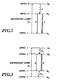
- FIG. 2 An optical transition of the objective EDFA is shown in Fig. 2 where three different energy levels are' indicated by Level 1, Level 2, and Level 3, respectively.
- a population inversion between Level 1 and Level 2 is done by pumping from Level 1 to Level 3 and then relaxing from Level 3 to Level 2.
- This kind of the induced emission can be referred as a three-level system.
- a four-level system can be defined that a final level of the induced emission is not a ground level but a first level (Level 1) which is higher than the ground level. Comparing the three-level system with the four-level system, the former is hard to attain the population inversion so that an ending level of the induced emission is in a ground state. Accordingly, the three-level system EDFA requires enhanced optically pumping light intensity, and also the fiber itself should be of having the properties of low-loss and high ⁇ n. In this case, the high ⁇ n is for effective optically pumping.
- Wavelength dependencies of the silica-based EDFA and the tellurite-based EDFA are illustrated in Fig. 4. As shown in the figure, it can be expected that the tellurite-based EDFA will attain a broadband optical amplification broader than that of the silica-based EDFA. Comparing with the silica-based glass and the non-silica-based glass, a transmission loss at a communication wavelength of the latter is substantially larger than that of the former. In the optical fiber amplifier, therefore, the loss leads to a substantial decrease in gain.
- the amplification band of tellurite glass is close to the one shown in Fig 4. If the loss is comparatively large, on the other hand, the amplification band of tellurite glass is narrowed.
- a wavelength at which a chromatic dispersion value takes zero is in the wavelengths longer than 2 ⁇ m.
- a chromatic dispersion value is generally -100 ps/km/nm or less at 1.55 ⁇ m band.
- a chromatic dispersion of a short optical fiber of about 10 m in length also takes the large value of -1 ps/nm or less.
- tellurite EDFA For the use of tellurite EDFA in long-distance and high-speed WDM transmission, therefore, it is need to bring the chromatic dispersion close to zero as far as possible.
- the tellurite-based optical fiber cannot utilize the technique adopted in the silica-based optical fiber that brings the chromatic dispersion value at 1.55 ⁇ m band close to zero by optimizing the construction parameters of the fiber.
- the tellurite-based optical fiber can be used as a host of praseodymium (Pr) for 1.3 ⁇ m band amplification. As described above, however, the tellurite-based optical fiber has a large chromatic dispersion value as the absolute value. In the case of amplifying a high-speed optical signal by using the tellurite-based optical fiber, a distortion of pulse wavelength can be induced and thus the chromatic dispersion value should be corrected for. If not, the use of tellurite glass in an optical communication system falls into difficulties.
- non-silica-based topical fiber such as a tellurite optical fiber as an optical amplification or nonlinear optical fiber
- a silica-based optical fiber to form the junction between these fibers with low-loss and low reflection.
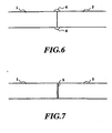
- these fibers have their own core refractive indexes which are different from each other. If these fibers are connected together as shown in Figs. 6 and 7, a residual reflection can be observed so that the junction appropriately adaptable to practical use cannot be implemented.
- reference numeral 1 denotes a non-silica-based optical fiber
- 2 denotes a silica-based optical fiber
- 5 denotes an optical binder
- 6 denotes a binder.
- a zirconium-doped fluoride fiber, an indium-doped fluoride fiber, chalcogenide glass fiber (i.e., glass composition: As-S), and a tellurite glass fiber have their own core's refractive indexes of 1.4 to 1.5, 1.45 to 1.65 and 2.4 and 2.1, respectively, depending on the variations in their glass compositions. If one of those fibers is connected to a silica based optical fiber (core's refractive index is about 1.50 or less), a return loss R can be obtained by the formula (2) described below.
- the unit of R is dB and the residual reflective index is expressed in a negative form while the return loss is expressed in a positive form as an absolute value of the residual reflective index.
- the return loss can be obtained by the equation (1) below.
- n NS and n S are core's refractive indexes of silica and non-silica optical fibers, respectively.
- the return loss between the silica-based optical fiber and the zirconium-doped fluoride optical fiber, indium-doped optical fluoride fiber, chalcogenide glass fiber (i.e., glass composition: As-S), or tellurite glass fiber is 35 dB or more, 26 dB or more, 13 dB, or 16 dB, respectively.
- the return loss can be increased (while the residual reflection coefficient can be decreased) by bringing their refractive indexes to that of the silica-based optical fiber's core by modifying their glass compositions, respectively.
- the modification of glass composition leads to the formation of practical optical fiber under the constraint that the glass composition should be precisely formulated in the process of forming a fiber in a manner which is consistent with an ideal glass composition for the process of forming a low-loss fiber).
- a coupling between the silica-based optical fiber and the non-silica-based optical fiber has the following problems.
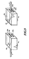
- a non-silica-based optical fiber 1 and a silica-based optical fiber 2 are held in housings 7a and'7b, respectively.
- the fibers 1, 2 are positioned in their respective V-shaped grooves on substrates 8a, 8b and fixed on their respective housings 7a, 7b by means of bonding agents 10a, 10b and fiber-fixing plates 9a, 9b.
- the coupling between the non-silica-based optical fiber 1 and the silica-based optical fiber 2 are carried out by using an optical bonding agent 5 made of ultraviolet-curing region after adjusting the relative positions of the housings 7a, 7b so as to match their optical axes.
- the coupling end of the housing 7a is perpendicular to the optical axis of the non-silica-based optical fiber and also the coupling end of the housing 7b is perpendicular to the optical axis of the silica-based optical fiber, so that if the reflection of light is occurred at a boundary surface of the coupling the reflected light returns in the revers direction, resulting in a falloff in the return loss.
- the conventional technology uses the dielectric film 18 to reduce the reflection from the boundary surface of the coupling.
- the conventional coupling requires a precision adjustment to a refractive index of the optical biding agent 5 and a refractive index and thickness of the dielectric film 18. That is, their refractive indexes must satisfy the following equations (2) and (3) if a core's refractive index of the non-silica-based optical fiber 1 is n 1 and a core's refractive index of the silica-based optical fiber 2 is n 2 .
- a refractive index of the optical binding agent 5 is adjusted to n 1 , while a refractive index and a thickness of the dielectric film 18 is adjusted to n 1 and t f , respectively, so as to satisfy the following equations (2), (3).
- n f n 1 ⁇ n 2
- t f ⁇ 4 n 1 ⁇ n 2
- ⁇ is a signal wavelength (i.e., the wavelength to be used).
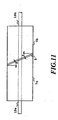
- a process of coupling two different optical fibers in accordance with another conventional technology comprises the steps of: holding an optical fiber 9a on a housing 7b and also holding an optical fiber 9a on a housing 7b; positioning these housings 7a, 7b in their right places so that a coupling end of the housing 7a that holds the optical fiber 19a and a coupling end of housing 7b that holds the optical fiber 19b are positioned with a ⁇ -degree slant with respect to a direction perpendicular to the optical axes of the optical fibers 19a, 19b; and connecting the housing 7a and the housing 7b together after the positioning of the housings so as to concentrically adjust the optical axes in a straight line.
- the process is a so-called slant coupling method for realizing the coupling with low-reflection and low fiber-loss.
- this process is only applied to the fibers when their core refractive indexes are almost the same, so that it cannot be applied to the coupling between the non-silica-based optical fiber and the silica-based optical fiber which have different core refractive indexes with respect to each other.
- a first object of the present invention is to provide a tellurite glass fiber of high ⁇ n and low fiber-loss.
- a second object of the present invention is to provide a tellurite glass fiber that includes the capability of realizing a broadband EDFA doped with an optically active rare earth element, which cannot be realized by the conventional glass compositions.
- a third object of the present invention is to provide a broadband, optical amplification medium that includes the capability of acting at wavelengths, especially from 1.5 ⁇ m to 1.7 ⁇ m, and also to provide an optical amplifier and a laser device which use such a medium and act at wavelengths in a broad range and have low-noise figures.
- a tellurite glass as a glass material for an optical fiber or an optical waveguide characterised by comprising:
- an optical amplification medium comprised of an optical amplifier or an optical waveguide having a core glass and a clad glass, wherein at least one of the core glass and the clad glass is made of the tellurite glass described above.
- an optical amplification medium comprised of an optical amplifier or an optical waveguide having a core glass and a clad glass, wherein the core glass is made of a tellurite glass having a composition of:
- At least one of the core glass and the clad glass may contain erbium or erbium and ytterbium.
- At least one of the core glass and the clad glass may contain at least one selected from a group consisting of boron (B), phosphorus (P), and hydroxyl group.
- At least one of the core glass and the clad glass may include an element selected from a group consisting of Ce, Pr, Nd, Sm, Tb, Gd, Eu, Dy, Ho, Tm, and Yb.
- a laser device comprising an optical cavity and an excitation light source, wherein at least one of optical amplification media in the optical cavity is one of the novel optical amplification media described above.
- a laser device having a plurality of optical amplification media comprised of optical fibers that contain erbium in their cores and arranged in series, wherein each of the optical amplification media is one of the novel optical amplification media described above.
- a laser device having an amplification medium and an excitation light source, wherein the amplification medium is one of the novel optical amplification media described above.
- an optical amplifier having an optical amplification medium, an input device that inputs an excitation light and a signal light for pumping the optical amplification medium, wherein the optical amplification medium is one of the novel optical amplification media described above.
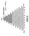
- FIG. 12 and Fig. 13 illustrates a composition range that shows interrelationship among ingredients of the glass composition.
- a thermal stability of the glass composition for preparing a fiber can be estimated by a technique of differential scanning calorimetry (DSC) generally used to indicate phase changes, so that a glass composition that has a larger value of Tx-Tg (Tx: crystallization temperature, and Tg: glass transition temperature) is a more stable glass composition.
- the process for preparing a single-mode optical fiber includes the steps of elongating and drawing a glass preform through the addition of heat, so that the glass preform is subjected to elevated temperatures twice. If a crystallization temperature (Tx) of the glass preform is almost the same order of a glass transition temperature (Tg), crystalline nuclei grow one after another resulting in an increase in scattering loss of the optical fiber.
- a low-loss optical fiber can be formed.
- a value of Tx - Tg is 120 °C or more and thus the glass composition can be used in the process for preparing the low-loss optical fiber.
- the low-loss optical fiber cannot be formed when a glass composition out of that region is used in the steps of preparing both of core and clad.
- the addition of Bi 2 O 3 has the large effect of stabilizing the glass.
- Each measurement is performed by breaking a glass sample, packing the bulk of broken glass (a piece of glass is 30 mg in weight) in a sealed container made of silver, and subjecting the glass in the container to the DSC measurement in an argon atmosphere at a heat-up rate of 10 °C/minute.
- This kind of effect can be also observed when a trivalent metal oxide (Al 2 O 3 , La 2 O 3 , Er 2 O 3 , Nd 2 O 3 , or the like) is added instead of Bi 2 O 3 .
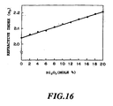
- Fig. 16 shows that the dependence of a refractive index (n D ) of TeO 2 -glass on an added amount of Bi 2 O 3 .
- n D refractive index
- TeO 2 -glass the refractive index of TeO 2 -glass
- Bi 2 O 3 the added amount of Bi 2 O 3 .
- the n D value varies from 2.04 to 2.2 if the added amount of Bi 2 O 3 varies from 0 to 20 mole %.
- optical fibers that have large and small values (from about 0.2 % to about 6 %) of relative refractive-index difference can be easily designed by changing the added amount of Bi 2 O 3 .
- the optical amplification medium comprises a core and a clad.
- the core is provided as an optical fiber made of a tellurite composition that consists of: 0 ⁇ Bi 2 O 3 ⁇ 20 (mole %); 0 ⁇ Na 2 O ⁇ 15 (mole %); 5 ⁇ ZnO ⁇ 35 (mole %); and 60 ⁇ TeO 2 ⁇ 90 (mole %).
- the clad comprises one of tellurite glass compositions (B1, C1, or D1) in the form of an optical fiber or an optical waveguide as a host of rare-earth element, where the composition (B1) consists of: 5 ⁇ Na 2 O ⁇ 35 (mole %); 0 ⁇ ZnO ⁇ 10 (mole %); and 55 ⁇ TeO 2 ⁇ 85 (mole %), the composition (C1) consists of: 5 ⁇ Na 2 O ⁇ 35 (mole %); 10 ⁇ ZnO ⁇ 20 (mole %); and 55 ⁇ TeO 2 ⁇ 85 (mole %), and the composition (D1) consists of: 0 ⁇ Na 2 O ⁇ 25 (mole %); 20 ⁇ ZnO ⁇ 30 (mole %); 55 ⁇ TeO 2 ⁇ 75 (mole %).
- the composition ranges of those compositions B1, C1, and D1 that stabilize glass are illustrated in Fig. 17.
- Glass prepared from the composition defined in the region shown in Fig. 17 shows that a value of Tx - Tg is 100 °C. Therefore, the glass is not crystallized during the fiber-forming process including a drawing step, so that it can be used in the process of forming a low-loss optical fiber.
- At least one of the tellurite glass compositions to be used in core and clad formations may be doped with erbium or erbium and ytterbium.
- a laser device comprises an optical amplification medium and an excitation light source, and is mainly characterized by the effective use of induced emission transition of Er from 4 I 13/2 level to 4 I 15/2 level.
- Fig. 18 is an energy level diagram of Er 3+ , which illustrates an induced emission from the upper level of 4 I 13/2 to the ground level of 4 I 15/2 thereinafter, referred as 4 I 13/2 ⁇ 4 I 15/2 emission).
- an optical amplifier or a laser device operating at wavelengths from 1.5 ⁇ m to 1.7 ⁇ m can be realized if its optical amplification medium is a tellurite glass fiber where erbium is added in at least a core portion.
- the tellurite glass contains at least one of boron, phosphorus, and hydroxyl group
- improvements in the properties of gain coefficient and noise figure can be also attained at the time of pumping 4 I 11/2 level by 0.98 ⁇ m light. That is, vibrational energies of B-O, P-O, and O-H which are approximately 1,400 cm -1 , 1,200 cm -1 , and 3,700 cm -1 , respectively, while phonon energy of the tellurite glass free of the above additive is 600 to 700 cm -1 , so that the tellurite glass containing at least one of boron, phosphorus, and hydroxyl group generates more than double the energy of the tellurite glass free of the additive.
- TeO 2 , ZnO, Na 2 NO 3 , and Bi 2 O 3 were formulated so as to be prepared both as background and inventive compositions of TeO 2 (75 mole %)-ZnO (20 mole %)-Na 2 O (5 mole %), TeO 2 (77 mole %)-ZnO (15.5 mole %)-Na 2 O (6 mole %) Bi 2 O 3 (1.5 mole %), and TeO 2 (73.5 mole %)-ZnO (15.5 mole %)-Na 2 O (6 mole %)-Bi 2 O 3 (5 mole %) after melting.
- Tx - Tg related to the thermal stability of glass is based on the measurement carried out on the bulk glass unless otherwise specified.
- An optical amplification medium was prepared as an optical fiber.
- a core of the optical fiber was made of a glass composition of TeO 2 (68.6 mole %)-Na 2 O (7.6 mole %)-ZnO(19.0 mole %)-Bi 2 O 3 (4.8 mole %) as a core material and doped with 1,000 ppm of erbium.
- a clad of the optical fiber was made of a glass composition of TeO 2 (71 mole %) -Na 2 O (8 mole %)-ZnO(21 mole %). Therefore, the optical fiber was characterized by having a cut-off wavelength of 1.3 ⁇ m and a relative refractive index difference between the core and the clad of 2 %.
- an optical amplifier for 1.5 to 1.7 ⁇ m band was assembled using that optical amplification medium.
- the optical amplifier was subjected to an amplification at a pump wavelength is 0.98 ⁇ m.
- a DFB laser was used as a light source for generating a signal light at 1.5 to 1.7 ⁇ m band.
- An amplification optical fiber is prepared as a an optical fiber (4 m in length) doped with 1,000 ppm of erbium in its core and subjected to a measurement for determining the amplification characteristics of the fiber at 1.5 ⁇ m band.
- a core glass Composition is of TeO 2 (68.6 mole %)-ZnO (19 mole %)-Na 2 O (7.6 mole %)-Bi 2 O 3 (4.8 mole %) and doped with 5 weight % of P 2 O 5
- a clad composition is of TeO 2 (71 mole %)-Na 2 O (8 mole %)-ZnO (21 mole %).
- the optical fiber has a core/clad refractive index difference of 2.5 % and a cut-off wavelength of 0.96 ⁇ m.
- a small signal gain at 1.5 ⁇ m band of the amplification optical fiber is measured using 0.98 ⁇ m light as an excitation light from a light source (a semiconductor laser), resulting in an increase in a gain efficiency of the optical fiber. That is, the gain efficiency of the optical fiber reaches a value of 2 dB/mW which is approximately five times as large as that of an optical fiber without containing P 2 O 5 .
- a gain spectrum at a saturated region when an input signal level is -10 dBm is measured, resulting in a flat gain at a bandwidth of 90 nm from 1,530 nm to 1, 620 nm (an excitation intensity is 200 mW).
- a noise figure of 7 dB is observed when the optical fiber does not contain P 2 O 3
- a noise of 4 dB is observed when the optical fiber contains P 2 O 3 .
- Amplification optical fibers are prepared using a core glass composition of TeO 2 (68.6 mole %)-ZnO (19 mole %)-Na 2 O (7.6 mole %)-Bi 2 O 3 (4.8 mole %) and doped with or without 5,000 ppm of hydroxyl (OH) radical and. 1, 000 ppm of Er.
- the optical fiber containing the OH-radical shows a gain factor three-times as large as that of the optical fiber without containing the OH-radical. The reason is that the OH-radical has a comparatively large signal energy of 3,700 cm -1 that causes a slight relaxation of the 4 I 13/2 level which is a starting level of the amplification by a multiple-phonon emission.
- an excitation light source is a laser diode of 1.48 ⁇ m to introduce light into an end of the optical fiber.
- the other end of the optical fiber is beveled at an angle 10 to prevent Presnel reflection on the fiber's end surface.
- an output spectrum of light passing through the optical fiber is measured.
- a broad emission spectrum of 1.46 ⁇ m to 1.64 ⁇ m is observed, so that we found that the optical fiber can be used as a broad band super-luminescent laser.
- An amplification optical fiber is prepared using a glass composition of TeO 2 (70 mole %)-ZnO (18 mole %)-Na 2 O (6 mole %)-Bi 2 O 3 (6 mole %) as a core material and doped with 2,000 ppm of erbium and a glass composition of TeO 2 (68 mole %)-ZnO (22 mole %)-Na 2 O (7 mole %)-Bi 2 O 3 (3 mole %) as a clad material.
- the optical fiber has a cut-off wavelength of 1.1 ⁇ m, and a core/clad relative refractive index difference of 1.8 %, and also it shows a fiber-loss at 1.3 ⁇ m of 40 dB/km.
- an optical amplifier is constructed using the optical fiber of 4 m in length as an optical amplification medium and subjected to an optical amplification test.
- a bidirectional pumping of a forward pump wavelength of 0.98 ⁇ m and a backward pump wavelength of 1.48 ⁇ m is used.
- a small signal gain of 5 dB or more is observed at 110 nm bandwidth of 1,500 nm to 1,630 nm.
- a noise figure of 5 dB or less is observed at a wavelength of 1,530 nm or more.
- An optical amplifier is constructed using the same optical fiber as that of Example 6 except that the fiber length of this example is 15 m.
- An optical amplification test is performed using the optical amplifier on condition that a bidirectional pump wavelength is 1.48 ⁇ m with a coincidence of the front and backward pump wavelengths. As a result, especially at 50 nm bandwidth of 1,580 nm to 1,630 nm, a small signal gain of 35 dB or more is observed. At this time, a noise figure of 5 dB is observed.
- a laser is constructed using the same optical fiber as that of Example 6 except that the fiber length of this example is 15 m.
- a cavity is also constructed using a total reflection mirror and a fiber-bragg-grating having a reflectivity of 3 %.
- a bidirectional pump wavelength is 1.48 ⁇ m with a coincidence of the front and backward pump wavelengths.
- an optical-power output of 150 mW at a wavelength of 1,625 nm is attained when an incident pump intensity is 300 mW.
- This kind of the high power cannot be generated by the conventional silica- and fluoride-based optical fibers.
- An amplification optical fiber is prepared using a glass composition of TeO 2 (68 mole %)-ZnO (13 mole % ) -Na 2 O (4 mole %)-Bi 2 O 3 (15 mole %) as a core material and doped with 3 weight % of erbium and a glass composition of TeO 2 (69 mole %)-ZnO (21 mole %) -Na 2 O (8 mole %)-Bi 2 O 3 (2 mole %) as a clad material.
- the optical fiber has a cut-off wavelength of 1.1 ⁇ m, and a core/clad relative refractive index difference of 5 %.
- a small-sized optical amplifier is constructed using a 3-cm piece of the optical fiber as an optical amplification medium and subjected to an optical amplification test.
- a forward pump wavelength of 1.48 ⁇ m is used.
- a wavelength tunable laser operating at 1.5 ⁇ m to 1.7 ⁇ m bands is used as a signal light source.
- a small signal gain of 20 dB or more is observed at 180 nm bandwidth of 1,530 nm to 1,610 nm.
- a noise figure of 7 dB or less is observed at a wavelength of 1,530 nm or more.
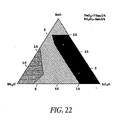
- TeO 2 -ZnO-Li 2 O-Bi 2 O 3 is formulated so that all of them contain Bi 2 O 3 with a fixed concentration (5 mole %) and other ingredients with varied concentrations.
- thermally stable glasses are obtained if the respective glass compositions are included in the region A in the figure.
- Tx crystallization temperature
- Tg glass transition temperature
- the thermally stable optical glasses allow optical fibers having the properties of low fiber-loss and also allow the mass production of the optical fiber with enhanced yields.
- low-priced optical fibers become feasible.
- a glass composition of TeO 2 (80 mole %)-ZnO (5 mole %)-Li 2 O (10 mole %)-Bi 2 O 3 (5 mole %) is selected and used as a core material.
- the core material is doped with 2,000 ppm of erbium.
- a glass composition of TeO 2 (75 mole %)-ZnO (5 mole %)-Li 2 O (15 mole %)-Bi 2 O 3 (5 mole %) is selected and used as a clad material.
- an optical fiber having a cut-off wavelength of 1.1 ⁇ m and a core/clad relative refractive index difference of 2.5 % is formed using these materials.
- the resulting optical fiber is used as an amplification medium with a fiber-loss at 1.2 ⁇ m of 20 dB/km.
- An optical amplifier is constructed using the amplification medium of 3 m in length and subjected to an amplification test on condition that a bidirectional pumping with a forward pump wavelength of 0.98 ⁇ m and a backward pump wavelength of 1.48 ⁇ m is used and a wavelength tunable laser operating at 1.5 ⁇ m to 1.7 ⁇ m bands is used as a signal light source.
- a bidirectional pumping with a forward pump wavelength of 0.98 ⁇ m and a backward pump wavelength of 1.48 ⁇ m is used and a wavelength tunable laser operating at 1.5 ⁇ m to 1.7 ⁇ m bands is used as a signal light source.
- a small signal gain of 20 dB or more is observed at 80 nm bandwidth of 1,530 nm to 1,610 nm.
- a noise figure of 5 dB or less is observed.
- a glass composition of TeO 2 (70 mole %)-ZnO (10 mole %) -Li 2 O (15 mole %)-Bi 2 O 3 (5 mole %) is selected and used as a core material.
- the core material is doped with 2,000 rpm of erbium.
- a glass composition of TeO 2 (70 mole %) -ZnO (7 mole %)-Li 2 O (18 mole %)-Bi 2 O 3 (5 mole %) is selected and used as a clad material.
- an optical fiber having a cut-off wavelength of 1.1 ⁇ m and a core/clad relative refractive index difference of 1.5 % is formed using these materials.
- the resulting optical fiber is used as an amplification medium with a fiber-loss at 1.2 ⁇ m of 60 dB/km.
- An optical amplifier is constructed using the amplification medium of 3 m in length and subjected to an amplification test as the same way as that of the aforementioned optical amplifier having the composition of the region B.
- a small signal gain of 20 dB or more is observed at 80 nm bandwidth of 1,530 nm to 1,610 nm.
- a noise figure of 5 dB or less is observed. Accordingly, the result indicates that the glass composition in the region A can be also used in the process of making a practical broadband EDFA.
- An amplification optical fiber is prepared using a glass composition of TeO 2 (68 mole %)-ZnO (13 mole %) -Na 2 O (4 mole %) -Bi 2 O 3 (15 mole %) as a core material and doped with 3 weight % of erbium and a glass composition of TeO 2 (69 mole %)-ZnO (21 mole %) -Na 2 O (8 mole %)-Bi 2 O 3 (2 mole %) as a clad material.
- the optical fiber has a cut-off wavelength of 1.4 ⁇ m, and a core/clad relative refractive index difference of 5 %.
- a small-sized optical amplifier is constructed using a 3-cm piece of the optical fiber as an optical amplification medium and subjected to an optical amplification test.
- a forward pump wavelength of 1.48 ⁇ m is used.
- a wavelength tunable laser operating at 1.5 ⁇ m to 1.7 ⁇ m bands is used as a signal light source.
- a small signal gain of 20 dB or more is observed at 80 nm bandwidth of 1,530 nm to 1,610 nm.
- a noise figure of 5 dB or less is observed.
- a tellurite glass is prepared by the process including the following steps. That is, at the start, raw materials of TeO 2 , ZnO, Na 2 CO 3 , and Bi 2 O 3 are formulated so as to become a formulation of TeO 2 (73.5 mole %)-ZnO (20 mole %)-Na 2 O (5 mole %)-Bi 2 O 3 (1.5 mole %) and a formulation of TeO 2 (73 mole %)-ZnO (20 mole %)-Na 2 O (5 mole %)-Bi 2 O 3 (2 mole %) after melting. Two different formulations are filled in respective 90 g volume crucibles and heated by an electric furnace at 800 °C for 2 hours in an oxygen atmosphere to melt those formulations, resulting in molten materials.
- each of the molten materials is casted in a cylindrical hollow-mold and an opening of the mold is capped with a cap without delay.
- the capped mold is laid in a horizontal position and left for 2 minutes and then allowed to reach room temperature, resulting a tellurite glass of 15 mm in outer diameter, 5 mm in inner diameter, and 130 mm in length in the form of a cylindrical tube having a bottom surface. In this manner, two glass tubes are obtained.
- the glass tubes are examined under a microscope. As a result, they can be distinguished microscopically. That is, the glass tube containing 1.5 mole % of Bi 2 O 3 has many crystallized portions in the proximity of its outside wall, while the glass tube containing 2.0 mole % of Bi 2 O 3 does not have any crystallized portion.
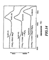
- Fig. 20 is a graphical representation of the results of the DSC measurement.
- a line (a) is for the glass having a composition of 73.5TeO 2 -20ZnO-5Na 2 O-1.5Bi 2 O 3 and a line (b) is for the glass having a composition of 73TeO 2 -20ZnO-5Na 2 O-2Bi 2 O 3 .
- a peak of crystallization is started at a temperature of about 350 °C and a value of Tx - Tg is 69.2 °C.
- the most striking characteristics of the tellurite glasses of Examples 1 to 12 is that each of them is formulated as a quadric system composition that consists four different ingredients including Bi 2 O 3 .
- This kind of the tellurite glass shows an excellent thermal stability, so that a fiber-loss can be minimized at the time of forming a fiber.
- the tellurite glass allows easily control of the refractive index, so that a fiber with a high ⁇ n can be formed. Therefore, the tellurite glass allows the scale-up of amplification bandwidth of the EDFA having the ternary-system composition which leads to a low degree of efficiency.
- the ternary-system composition disclosed in U.S. Patent No. 5,251,062 is less stable than the quadric system tellurite glass of the present invention, so that a minimum of the fiber-loss at 1.5 ⁇ m is 1,500.dB/km.
- we studies various compositions for the purpose of the reduction in fiber-loss and finally find that the quadric system tellurite composition containing Bi 2 O 3 allows a dramatic decrease in the fiber-loss.
- the tellurite glass allows easily control of the refractive index and a fiber with a high ⁇ n can be formed. Therefore, the present invention realizes the tellurite EDFA with a low fiber-loss at first.
- the tellurite glass that contains Bi 2 O 3 has the composition of 78 % TeO 2 - 18 % Bi 2 O 3 and 80 % TeO 2 - 10 % Bi 2 O 3 - 10 % TiO 2 .
- this composition is much different from the quadric system composition of the present invention.
- thermal stability of glass and fiber-loss even though these properties are very important.
- the quadric system tellurite glass having a core composition of 77 % TeO 2 - 6.0 % Na 2 O - 15.5 % ZnO - 1.5 % Bi 2 O 3 is described in Optical Materials and Optic Letters cited above, especially in Optical Materials which is also disclose a fiber-loss at 1.55 ⁇ m band of 1,500 dB/km.
- this fiber-loss is too high, and also there is no description or teach that indicates or recalls the improvements in thermal stability by an addition of Bi 2 O 3 .
- a refractive index of glass is adjusted by an appropriate adjusting agent.
- the addition of Bi 2 O 3 is exactly what the optical fiber needs for that adjustment.
- tellurite glasses having Bi 2 O 3 -contained quadric system compositions are effective on a reduction in fiber-loss.
- a thermal stability of the tellurite glass is dramatically improved by the addition of Bi 2 O 3 in concentration of over 4 %, and thus the tellurite glass optical fiber can be provided as the one having the properties of low fiber-loss.
- a high ⁇ n fiber can be formed as a result of controlling Bi 2 O 3 content in the core and clad glasses without restraint. Consequently, the scale-up of amplification band region of low-efficient three-level system EDFA by a synergistic effect of these improvements.
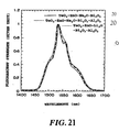
- the tellurite glass or the tellurite optical fiber contains aluminum (Al) as a host. It is also known that if SiO 2 -based glass contains Al a dented portion between 1.53 ⁇ m and 1.56 ⁇ m of a cross-section of stimulated emission of Er in the glass is despaired and also the gain spectrum is flatten at wavelengths of 1.54 ⁇ m to 1.56 ⁇ m (Emmanue Desurvire, "Erbium-Doped Fiber Amplifiers", John Wiley & Sons, 1994). However, this is an effect of A1 on the silica-based optical fiber, so that the effect on the tellurite glass is still unknown.
- the present inventors finally found the following facts. That is, the addition of Al in tellurite glass leads to the effects of disappearing a dented portion between 1.53 ⁇ m and 1.56 ⁇ m of a cross-section of stimulated emission of Er in the glass and increasing variations in the cross-section, resulting in reduction of a gain difference between 1.55 ⁇ m band and 1.6 ⁇ m band.
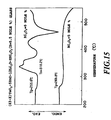
- Fig. 21 is a spectrum diagram that illustrates each 1.5 ⁇ m emission spectrum of Er in glasses having their respective compositions of:
- an intensity of emission spectrum of the glass containing Al 2 O 3 at a wavelength of around 1.6 ⁇ m is stronger than that of the glass without Al 2 O 3 , and also a depth of the dent between 1.53 ⁇ m and 1.56 ⁇ m of the former is disappeared or shallower than that of the latter.
- An erbium-doped tellurite optical fiber is prepared using the Al 2 O 3 -contained glass (TeO 2 -ZnO-Na 2 O- Bi 2 O 3 system glass).
- the obtained fiber has a cut-off wavelength of 1.3 ⁇ m, Er-content of 4,000 ppm, and length of 0.9 m.
- the fiber is optically pumped at 1.48 ⁇ m with the power of 200 mW, resulting in a 10 dB or less gain difference between 1.56 ⁇ m and 1.60 ⁇ m.
- EDFA is constructed using the above erbium-doped optical fiber as an optical amplifier and a fiber-bragg-grating as a gain-equalizing device.
- the obtained EDFA showed 1 dB or less gain difference between 1.53 ⁇ m and 1.60 ⁇ m.
- an EDFA using the Al 2 O 3 -absent fiber showed 15 dB or more gain difference between 1.56 ⁇ m and 1.60 ⁇ m.
- the gain deviation at wavelengths from 1.56 ⁇ m to 1.60 ⁇ m could not be reduced to 1 dB or less across a width of 70 nm in spite of using the gain-equalizing device.
- 100 glass samples are prepared from a glass composition of TeO 2 -ZnO-Li 2 O-Na 2 O-Bi 2 O 3 . That is, the glass samples are made of materials containing 75 mole % TeO 2 and 5 mole % Bi 2 O 3 or materials containing 80 mole % TeO 2 and 5 mole % Bi 2 O 3 . In each of the materials, furthermore, the contents of other ingredients are varied. Then, each of the glass samples is broken into pieces and powdered in an agate mortar.
- an optical amplification medium is prepared as a fiber having a cut-off wavelength of 1.1 ⁇ m and a core/clad relative refractive index difference of 1.6 %. That is, a core of the fiber is formed from a glass composition the glass composition of TeO 2 (75 mole %)-ZnO (5 mole %)-Li 2 O (12 mole %)-Na 2 O (3 mole %)-Bi 2 O 3 (5 mole %) doped with 2,000 ppm of erbium, and also a clad of the fiber is formed from a glass composition of TeO 2 (75 mole %)-ZnO (2 mole %)-Li 2 O (15 mole %)-Na 2 O (3 mole %)-Bi 2 O 3 (5 mole %).
- the obtained medium is cut to a fiber of 3 m in length to construct an optical amplifier.
- the optical amplifier is subjected to an amplification test.
- a bidirectional pumping procedure with a forward-pump wavelength of 0.98 ⁇ m and a backward-pump wavelength of 1.48 ⁇ m is used.
- a wavelength tunable laser that covers from 1.5 ⁇ m to 1.7 ⁇ m band is used as an optical signal source.
- a small signal gain of 20 dB or more is obtained at a bandwidth of 80 nm ranging from 1,530 to 1,610 ⁇ m.
- a noise figure (NF) is 5 dB or less.
- a glass composition of TeO 2 (80 mole %)-ZnO (6 mole %)-Li 2 O (4 mole %)-Na 2 O (5 mole %) -Bi 2 O 3 (5 mole %) is selected from among allowable compositions in the region so as to be provided as a core material.
- a glass composition of TeO 2 (80 mole %)-ZnO (2 mole %)-Li 2 O (6 mole %)-Na 2 O (7 mole %)-Bi 2 O 3 (5 mole %) is selected so as to be provided as a clad material.
- the core material is doped with 2,000 ppm of erbium. Then, an optical fiber having a cut-off wavelength of 1.1 ⁇ m and a core/clad relative refractive index difference of 1.5 %. The obtained fiber is provided as an optical amplification medium. A fiber-loss of the medium is 0.07 dB/m at 1.2 ⁇ m.
- the medium is cut to a fiber of 3 m in length to construct an optical amplifier.
- the optical amplifier is also subjected to an amplification test.
- a small signal gain of 20 dB or more over is obtained at a bandwidth of 80 nm ranging from of 1,510 to 1,630 nm.
- a noise figure (NF) is 5 dB or less.
- An optical amplifier is constructed by the same way as that of 14 except of using a fiber of 15 m length in this Example and subjected to an amplification test.
- a bidirectional pumping procedure in which the front and the backward wavelengths are identical with each other is used.
- a wavelength tunable laser that covers from 1.5 ⁇ m to 1.7 ⁇ m band is used as an optical light source.
- a small signal gain of 20 dB or more is obtained at a bandwidth of 70 nm ranging from 1,560 to 1,630 nm. At this time, noise figure is 5 dB or less.
- a laser is constructed using a fiber (15 m in length) which is prepared as the same way as that of Example 14 .
- a cavity is constructed using a fiber-bragg- grating that has a refractive index of 3 % at a wavelength of 1,625 nm with respect to a total reflection mirror.
- a bidirectional pumping procedure in which the forward and the backward wavelengths are of 1.48 ⁇ m.
- the laser generated a high-power of 150 mW at 1,625 nm wavelength, which could not be attained by silica-based and fluoride-based optical fibers.
- 50 glass samples are prepared from a glass composition of TeO 2 -ZnO-Li 2 O-Al 2 O 3 -Bi 2 O 3 .
- the samples have 2 mole of Al 2 O 3 and 12 mole % of Li 2 O except that every sample have its own ratios of other ingredients.
- each of the glass samples is broken into pieces and powdered in an agate mortar.
- 30 mg of the obtained powder is filled into a sealed container made of silver and then subjected into the DSC measurement in an argon atmosphere at a heat-up rate of 10 °C/minute, resulting in a heat-stable glass having 120 °C or more of Tx - Tg in a region defined as A in Fig. 24.
- the heat-stable glass allows a fiber having a lower loss of 0.1 dB/m or less.
- the effects of adding Al 2 O 3 into the glass composition allows a broader area of induced-emission cross section, so that an amplification bandwidth of EDFA can be broadened.
- an optical amplification medium is prepared as a fiber having a cut-off wavelength of 1.1 ⁇ m and a core/clad relative refractive index difference of 1.6 %.
- a core of the fiber is formed from a glass composition the glass composition selected from the region in Fig. 29, that is, TeO 2 (82 mole %)-ZnO (1 mole %)-Li 2 O (12 mole %)-Al 2 O 3 (2 mole %)-Bi 2 O 3 (3 mole %) doped with 2,000 ppm of erbium.
- a clad of the fiber is formed from a glass composition of TeO 2 (75 mole %)-ZnO (3 mole %)-Li 2 O (18 mole %)-Bi 2 O 3 (4 mole %).
- a fiber-loss at 1.2 ⁇ m is 0.07 dB/m.
- the obtained medium is cut to a fiber of 3 m in length to construct an optical amplifier.
- the optical amplifier is subjected to an amplification test.
- a bidirectional pumping procedure with a forward-pump wavelength of 0.98 ⁇ m and a backward-pump wavelength of 1.48 ⁇ m is used.
- a wavelength tunable laser that covers from 1.5 ⁇ m to 1.7 ⁇ m band is used as an optical signal source.
- a small signal gain of 20 dB or more is obtained at a bandwidth of 80 nm ranging from 1,530 to 1,610 ⁇ m.
- a noise figure (NF) is 5 dB or less.
- a wavelength tunable ring laser is constructed using the same fiber (4 m in length) as that of Embodiment 30, and also a wave tunable filter for wavelengths from 1.5 ⁇ m to 1.7 ⁇ m is used as a filter.
- a bidirectional pumping procedure in which the front and the backward wavelengths are identical with each other is used.
- the laser showed its broadband laser characteristic of 5 mW or more at a bandwidth of 135 nm ranging from 1,500 to 1,635 nm, which could not be attained by the silica-based and fluoride-based optical fiber.
- a clad of the fiber is formed from a glass composition of TeO 2 (75 mole %)-ZnO (17.5 mole %)-Na 2 O (5 mole %)-Bi 2 O 3 (2.5 mole %) glass.
- the spacing between adjacent scattering points i.e., a point where a fiber-loss is remarkably increased by a scattering of light from particles such as crystals
- the spacing between adjacent scattering points is 15 m or less
- a fiber-loss in the area without the scattering centers is 0.07 dB/m at a wavelength of 1.2 ⁇ m.
- the spacing between adjacent scattering centers is 100 m or more, and also a fiber-loss in the area without the scattering centers is 0.02 dB/m or less.
- a required fiber length for constructing EDFA is about 10 m.
Landscapes
- Physics & Mathematics (AREA)
- Optics & Photonics (AREA)
- Engineering & Computer Science (AREA)
- Electromagnetism (AREA)
- Chemical & Material Sciences (AREA)
- General Physics & Mathematics (AREA)
- Plasma & Fusion (AREA)
- Geochemistry & Mineralogy (AREA)
- Life Sciences & Earth Sciences (AREA)
- Chemical Kinetics & Catalysis (AREA)
- General Chemical & Material Sciences (AREA)
- Materials Engineering (AREA)
- Organic Chemistry (AREA)
- Signal Processing (AREA)
- Computer Networks & Wireless Communication (AREA)
- Lasers (AREA)
- Glass Compositions (AREA)
Description
- The present invention relates to a tellurite glass as a glass material for an optical fiber and an optical waveguide, and in particular a broadband optical amplification medium using the tellurite glass which is capable of working even at wavelengths of 1.5 µm to 1.7 µm. The present invention also relates to a broadband optical amplifier and a laser device using the broad band optical amplification medium.
- The technology of wavelength division multiplexing (WDM) has been studied and developed for expanding transmission volume of optical communication systems and functionally improving such systems. The WDM is responsible for combining a plurality of optical signals and transmitting a combined signal through a single optical fiber. In addition, the WDM is reversibly responsible for dividing a combined signal passing through a single optical fiber into a plurality of optical signals for every wavelength. This kind of transmitting technology requires a transit amplification just as is the case with the conventional one according to the distance of transmitting a plurality of optical signals of different wavelengths through a single optical fiber. Thus, the need for an optical amplifier having a broad amplification waveband arises from the demands for increasing the optical signal's wavelength and the transmission volume. The wavelengths of 1.61 µm to 1.66 µm have been considered as appropriate for conserving and monitoring an optical system, so that it is desirable to develop an optical source and an optical amplifier for that system.
- In recent years, there has been considerable work devoted to research and development on optical fiber amplifiers that comprise optical fibers as optical amplification materials, such as erbium (Er) doped optical fiber amplifiers (EDFAs), with increasing applications to the field of optical communication system. The EDFA works at a wavelength of 1.5 µm where a loss of silica-based optical fiber decreases to a minimum, and also it is known for its excellent characteristics of high gain of 30 dB or more, low noise, broad gain-bandwidth, no dependence on polarized waves, and high saturation power.
- As described above, one of the remarkable facts to be required of applying the above EDFA to the WDM transmission is that the amplification waveband is broad. Up to now, a fluoride EDFA using a fluoride glass as a host of an erbium-doped optical fiber amplifier has been developed as a broad amplification band EDFA.
- In U.S. Patent Nos. 3,836,868, 3,836,871, and 3,883,357, Cooley et al. discloses the possibility of laser oscillation to be caused by tellurite glass containing an rare earth element. In this case, however, Cooley et al. have no idea of forming tellurite glass into an optical fiber because there is no description concerned about the adjustment of refractive index and the thermal stability of tellurite glass to be required for that formation.
- In U.S. Patent No. 5,251,062, Snitzer et al. insists that tellurite glass play an important role in extending the EDFA's amplification band and it should be formed into a fiber which is absolutely essential to induction of an optical amplification. Thus, they disclose the allowable percent ranges of ingredients in tellurite-glass composition in a concretive manner. The tellurite-glass composition includes a rare earth element as an optically active element and can be formed into a fiber. More specifically, the tellurite-glass composition of Snitzer et al. is a ternary composition comprising TeO2, R2O, and QO where R denotes a monovalent metal except Li and Q denotes a divalent metal. The reason why Li is excluded as the monovalent metal is that Li depresses thermal stability of the tellurite-glass composition.
- In U.S. Patent No. 5,251,062, furthermore, Snitzer et al. make a comparative study of fluorescence erbium spectra of silica and tellurite glass and find that the tellurite glass shows a broader erbium spectrum compared with that of the silica glass. They conclude that the ternary tellurite glass composition may allow a broadband amplification of EDFA and an optically active material such as praseodymium or neodymium may be added in that composition for inducing an optical amplification. In this patent document, however, there is no concrete description of the properties of gain, pump wavelength, signal wavelength, and the like which is important evidence to show that the optical amplification was actually down. In other words, U.S.. Patent No. 5,251,062 merely indicate the percent ranges of ingredients of ternary tellurite glass composition that can be used in an optical fiber.
- Furthermore, Snitzer et al. show that thermal and optical features of various kinds of tellurite glass except of those described in U.S. Patent No. 5,251,062 in a technical literature (Wang et al., Optical Materials, vol. 3 pages 187-203, 1994; hereinafter simply referred as "Optical Materials"). In this literature, however, there is also no concrete description of optical amplification and laser oscillation.
- In another technical literature (J. S. Wang et al., Optics Letters, vol. 19 pages 1448-1449, 1994; hereinafter simply referred as "Optics Letters") published in right after the literature mentioned above, Snitzer et al. show the laser oscillation for the first time caused by using a single mode optical fiber of neodymium-doped tellurite glass. The single mode fiber comprises a core having the composition of 76.9 % TeO2 - 6.0 % Na2O - 15.5 % ZnO - 1.5 % Bi2O3 - 0.1 % Nd2O3 and a clad having the - 1.5 % Bi2O3 - 0.1 % Nd2O3 and a clad having the composition of 75 % TeO2 - 5.0 % Na2O - 20.0 % ZnO and allows 1,061 nm laser oscillation by 81 nm pumping. In this literature, there is no description of a fiber loss. In Optical Materials, on the other hand, there is a description of which the loss for an optical fiber having a core composition of Nd2O3 - 77 % TeO2 - 6.0 % Na2O - 15.5% ZnO - 1.5 % Bi2O3 and a clad composition of 75 % TeO2 - 5.0 % Na2O- 20.0 % ZnO (it is deemed to be almost the same composition as that of Optics Letters) is 1500 dB/km at a wavelength of 1.55 µm (see Fig. 1 that illustrates a comparison between 4I13/2 to 4I15/2 Er3+ emission in tellurite glass and 4I13/2 to 4I15/2 Er3+ emission in fluoride glass). The core composition of this optical fiber is different from that of a ternary composition disclosed in U.S. patent No. 5,251,062 because the former includes Bi2O3. It is noted that there is no description or teach of thermal stability of Bi2O3-contained glass composition in the descriptions of Optics Letters, Optical Materials, and U.S. patent No. 5,251,062 mentioned above.
- However, the fluoride based EDFA has an amplification band of about 30 nm which is not enough to extend an amplification band of optical fiber amplifier for the purpose of extending the band of WDM.
- French Patent Application No. 2479180 discloses an infra red fibre optic device constructed from a glass comprising TeO2, WO3 and Bi2O3 (or Ta2O5) as essential constituents.
- European Patent Application No. 0430206 discloses a sealing glass comprising TeO2, B2O3, PbO and CdO as essential constituents. Optionally, the glass may also contain Bi2O3, among other things.
- United States Patent No. 3,661,600 discloses a glass with a high refractive index and a high dispersing ability, comprising TeO2, WO3, Li2O and CdO as essential constituents. Optionally, the glass may also contain Bi2O3, among other things.
- Patent Abstracts of Japan, Volume 096, No. 008, 30 August 1996 discloses use of a tellurite glass of composition TeO2 (77 mole %) - Na2O (6 mole %) - ZnO (15.5 mole %) - Bi2O3 (1.5 mole %) as the core material in an amplifying optical fibre.
- As described above, tellurite glass shows a comparatively broader fluorescence spectral band width, so that there is a possibility to extend the amplification band if the EDFA uses the tellurite glass as its host. In addition, the possibility of producing a ternary system optical fiber using the composition of TeO2, R2O, and QO (wherein R is a univalent metal except Li and Q is a divalent atom) has been realized , so that laser oscillation at a wavelength of 1061 nm by a neodymium-doped single mode optical fiber mainly comprising the above composition has been attained. In contrast, EDFA using tellurite glass is not yet realized. Therefore, we will describe the challenge to realize a tellurite-based EDFA in the following.
- First, the difference between the objective EDFA and the neodymium-doped fiber laser (i.e., the difference between 1.5 µm band emission of erbium and 1.06 µm band emission of neodymium in glass) should be described in detail.
- An optical transition of the objective EDFA is shown in Fig. 2 where three different energy levels are' indicated by
Level 1,Level 2, andLevel 3, respectively. For attaining an objective induced emission fromLevel 2 toLevel 1, a population inversion betweenLevel 1 andLevel 2 is done by pumping fromLevel 1 toLevel 3 and then relaxing fromLevel 3 toLevel 2. This kind of the induced emission can be referred as a three-level system. - In the case of the neodymium, as shown in Fig. 3, a four-level system can be defined that a final level of the induced emission is not a ground level but a first level (Level 1) which is higher than the ground level. Comparing the three-level system with the four-level system, the former is hard to attain the population inversion so that an ending level of the induced emission is in a ground state. Accordingly, the three-level system EDFA requires enhanced optically pumping light intensity, and also the fiber itself should be of having the properties of low-loss and high Δn. In this case, the high Δn is for effective optically pumping.
- Secondly, we will briefly described that an amplification band cannot be extended even if it is possible to perform an optical amplification when a transmission loss of fiber is large.
- Wavelength dependencies of the silica-based EDFA and the tellurite-based EDFA are illustrated in Fig. 4. As shown in the figure, it can be expected that the tellurite-based EDFA will attain a broadband optical amplification broader than that of the silica-based EDFA. Comparing with the silica-based glass and the non-silica-based glass, a transmission loss at a communication wavelength of the latter is substantially larger than that of the former. In the optical fiber amplifier, therefore, the loss leads to a substantial decrease in gain.
- As schematically shown in Fig. 5, if the loss is comparatively small, the amplification band of tellurite glass is close to the one shown in Fig 4. If the loss is comparatively large, on the other hand, the amplification band of tellurite glass is narrowed.
- In recent technical investigations on WDM transmission, by the way, it has been made attempts to speed up transmission through one channel for increasing transmission capacity. To solve this problem, it is necessary to optimize the chromatic dispersion characteristics of the Er-doped optical fiber. Up to now, however, no attention have been given to that characteristics.
- For the tellurite glass, a wavelength at which a chromatic dispersion value takes zero is in the wavelengths longer than 2 µm. In the case of a high NA (Numerical Aperture) fiber to be used in EDFA, a chromatic dispersion value is generally -100 ps/km/nm or less at 1.55 µm band. Thus, a chromatic dispersion of a short optical fiber of about 10 m in length also takes the large value of -1 ps/nm or less.
- For the use of tellurite EDFA in long-distance and high-speed WDM transmission, therefore, it is need to bring the chromatic dispersion close to zero as far as possible. As described above, however, as the material dispersion value of tellurite glass takes the value of zero at wavelengths of 2 µm and over. Therefore, the tellurite-based optical fiber cannot utilize the technique adopted in the silica-based optical fiber that brings the chromatic dispersion value at 1.55 µm band close to zero by optimizing the construction parameters of the fiber.
- Furthermore, the tellurite-based optical fiber can be used as a host of praseodymium (Pr) for 1.3 µm band amplification. As described above, however, the tellurite-based optical fiber has a large chromatic dispersion value as the absolute value. In the case of amplifying a high-speed optical signal by using the tellurite-based optical fiber, a distortion of pulse wavelength can be induced and thus the chromatic dispersion value should be corrected for. If not, the use of tellurite glass in an optical communication system falls into difficulties.
- Next, an optical-fiber splicing between a non-silica-based optical fiber and a silica-based optical fiber will be described below.
- For using the above non-silica-based topical fiber such as a tellurite optical fiber as an optical amplification or nonlinear optical fiber, there is a necessity to connect to a silica-based optical fiber to form the junction between these fibers with low-loss and low reflection. However, these fibers have their own core refractive indexes which are different from each other. If these fibers are connected together as shown in Figs. 6 and 7, a residual reflection can be observed so that the junction appropriately adaptable to practical use cannot be implemented. In Figs. 6 and 7,
reference numeral 1 denotes a non-silica-based optical fiber, 2 denotes a silica-based optical fiber, 5 denotes an optical binder, and 6 denotes a binder. In Fig. 6, furthermore, there is no optical binder applied on a boundary surface between the fibers. As shown in Fig. 8, therefore, the existence of residual reflection between the silica-basedoptical fibers optical fiber 1 degrades the quality of signal because of a ghost (which acts as noise) due to a reflected signal on the connected ends of the fibers. Therefore, the connected portion between those fibers require -60 dB or over as a residual reflection factor for an optical amplifier (see Takei et al. "Optical Amplifier Module", Okidenki Kaihatu, vol. 64, No. 1, pp 63-66, 1997). For example, a zirconium-doped fluoride fiber, an indium-doped fluoride fiber, chalcogenide glass fiber (i.e., glass composition: As-S), and a tellurite glass fiber have their own core's refractive indexes of 1.4 to 1.5, 1.45 to 1.65 and 2.4 and 2.1, respectively, depending on the variations in their glass compositions. If one of those fibers is connected to a silica based optical fiber (core's refractive index is about 1.50 or less), a return loss R can be obtained by the formula (2) described below. In this case, the unit of R is dB and the residual reflective index is expressed in a negative form while the return loss is expressed in a positive form as an absolute value of the residual reflective index. The return loss can be obtained by the equation (1) below.where nNS and nS are core's refractive indexes of silica and non-silica optical fibers, respectively. The return loss between the silica-based optical fiber and the zirconium-doped fluoride optical fiber, indium-doped optical fluoride fiber, chalcogenide glass fiber (i.e., glass composition: As-S), or tellurite glass fiber is 35 dB or more, 26 dB or more, 13 dB, or 16 dB, respectively. In the case of Zr-based and In-based fluoride optical fiber, the return loss can be increased (while the residual reflection coefficient can be decreased) by bringing their refractive indexes to that of the silica-based optical fiber's core by modifying their glass compositions, respectively. However, the modification of glass composition leads to the formation of practical optical fiber under the constraint that the glass composition should be precisely formulated in the process of forming a fiber in a manner which is consistent with an ideal glass composition for the process of forming a low-loss fiber). A coupling between the silica-based optical fiber and the non-silica-based optical fiber has the following problems. That is, conventional fusion splicing procedures cannot be applied because of the difference in softening temperatures of both fibers (i.e., 1,400 °C for the silica-based optical fiber and less than 500 °C for the non-silica-based one); the conventional optical connector coupling technologies cannot be applied because there is no appropriate coupling method for the non-silica-based optical fiber; and so on. Thus, a general coupling method for coupling the Zr-based or In-based optical fiber to the silica-based optical fiber without depending on its glass composition has been demanded. In addition, a general coupling method for reliably coupling the chalcogenide glass optical fiber or the tellurite optical fiber to the silica-based optical fiber with a low-loss and low-reflection.
- One of the conventional coupling technologies for solving such problems, Japanese Patent Application Laying-open No. 6-27343, is illustrated in Figs. 9 and 10. In this technology, a non-silica-based
optical fiber 1 and a silica-basedoptical fiber 2 are held inhousings 7a and'7b, respectively. Thefibers substrates 8a, 8b and fixed on theirrespective housings bonding agents plates dielectric film 18 applied on a coupling end of one of the housings for preventing a reflection to be generated by coupling the fibers together. The coupling between the non-silica-basedoptical fiber 1 and the silica-basedoptical fiber 2 are carried out by using anoptical bonding agent 5 made of ultraviolet-curing region after adjusting the relative positions of thehousings housing 7a is perpendicular to the optical axis of the non-silica-based optical fiber and also the coupling end of thehousing 7b is perpendicular to the optical axis of the silica-based optical fiber, so that if the reflection of light is occurred at a boundary surface of the coupling the reflected light returns in the revers direction, resulting in a falloff in the return loss. Accordingly, the conventional technology uses thedielectric film 18 to reduce the reflection from the boundary surface of the coupling. However, the conventional coupling requires a precision adjustment to a refractive index of the optical bidingagent 5 and a refractive index and thickness of thedielectric film 18. That is, their refractive indexes must satisfy the following equations (2) and (3) if a core's refractive index of the non-silica-basedoptical fiber 1 is n1 and a core's refractive index of the silica-basedoptical fiber 2 is n2. A refractive index of the opticalbinding agent 5 is adjusted to n1, while a refractive index and a thickness of thedielectric film 18 is adjusted to n1 and tf, respectively, so as to satisfy the following equations (2), (3).n n n - In the conventional technology, as described above, there is the need for precisely adjusting a refractive index of the
optical binder 5 and a refractive index and thickness of thedielectric film 18 for constructing a coupling portion with the properties of low-reflection and low-loss by using thedielectric film 18. It means that the precise adjustments leads to difficulties in implementing a coupling between the fibers favorably with an improvement in yield. - A process of coupling two different optical fibers in accordance with another conventional technology, as shown in Fig. 11, comprises the steps of: holding an
optical fiber 9a on ahousing 7b and also holding anoptical fiber 9a on ahousing 7b; positioning thesehousings housing 7a that holds theoptical fiber 19a and a coupling end ofhousing 7b that holds theoptical fiber 19b are positioned with a -degree slant with respect to a direction perpendicular to the optical axes of theoptical fibers housing 7a and thehousing 7b together after the positioning of the housings so as to concentrically adjust the optical axes in a straight line. The process is a so-called slant coupling method for realizing the coupling with low-reflection and low fiber-loss. However, this process is only applied to the fibers when their core refractive indexes are almost the same, so that it cannot be applied to the coupling between the non-silica-based optical fiber and the silica-based optical fiber which have different core refractive indexes with respect to each other. - A first object of the present invention is to provide a tellurite glass fiber of high Δn and low fiber-loss.
- A second object of the present invention is to provide a tellurite glass fiber that includes the capability of realizing a broadband EDFA doped with an optically active rare earth element, which cannot be realized by the conventional glass compositions.
- A third object of the present invention is to provide a broadband, optical amplification medium that includes the capability of acting at wavelengths, especially from 1.5 µm to 1.7 µm, and also to provide an optical amplifier and a laser device which use such a medium and act at wavelengths in a broad range and have low-noise figures.
- In a first aspect of the present invention, there is provided a tellurite glass as a glass material for an optical fiber or an optical waveguide, characterised by comprising:
- 4 < Bi2O3 ≤ 15 (mole %) ;
- 0 < Na2O ≤ 35 (mole %) ;
- 0 < ZnO ≤ 35 (mole %); and
- 55 ≤ TeO2 ≤ 90 (mole %).
-
- In a second aspect of the present invention, there is provided an optical amplification medium comprised of an optical amplifier or an optical waveguide having a core glass and a clad glass, wherein
at least one of the core glass and the clad glass is made of the tellurite glass described above. - In a third aspect of the present invention, there is provided an optical amplification medium comprised of an optical amplifier or an optical waveguide having a core glass and a clad glass, wherein
the core glass is made of a tellurite glass having a composition of: - 4 < Bi2O3 ≤ 15 (mole %), or more preferably 4 < Bi2O3 ≤ 7;
- 0 ≤ Na2O ≤ 35 (mole %);
- 0 ≤ ZnO ≤ 35 (mole %); and
- 55 ≤ TeO2 ≤ 90 (mole %), and the clad is made of a tellurite glass having a composition selected from a group of:
- a first composition including
5 < Na2O < 35 (mole %),
0 ≤ ZnO < 10 mole %), and
55 < TeO2 < 85 (mole %); - a second composition including
5 < Na2O < 35 (mole %),
10 < ZnO ≤ 20 mole %), and
55 < TeO2 < 85 (mole %); and - a third composition including
0 ≤ Na2O < 25 (mole %),
20 < ZnO ≤ 30 mole %), and
55 < TeO2 < 75 (mole %). -
- Here, at least one of the core glass and the clad glass may contain erbium or erbium and ytterbium.
- At least one of the core glass and the clad glass may contain at least one selected from a group consisting of boron (B), phosphorus (P), and hydroxyl group.
- At least one of the core glass and the clad glass may include an element selected from a group consisting of Ce, Pr, Nd, Sm, Tb, Gd, Eu, Dy, Ho, Tm, and Yb.
- In a fourth aspect of the present invention, there is provided a laser device comprising an optical cavity and an excitation light source, wherein
at least one of optical amplification media in the optical cavity is one of the novel optical amplification media described above. - In a fifth aspect of the present invention, there is provided a laser device having a plurality of optical amplification media comprised of optical fibers that contain erbium in their cores and arranged in series, wherein
each of the optical amplification media is one of the novel optical amplification media described above. - In a sixth aspect of the present invention, there is provided a laser device having an amplification medium and an excitation light source, wherein
the amplification medium is one of the novel optical amplification media described above. - In an seventh aspect of the present invention, there is provided an optical amplifier having an optical amplification medium, an input device that inputs an excitation light and a signal light for pumping the optical amplification medium, wherein
the optical amplification medium is one of the novel optical amplification media described above. - The above and other objects, effects, features and advantages of the present invention will become more apparent from the following description of embodiments thereof taken in conjunction with the accompanying drawings.
- Fig. 1 is a spectrum diagram that illustrates the 4I13/2-4I15/2 emission of Er in the tellurite glass;
- Fig. 2 is an energy-level diagram of 3-level system for Er3+ at around 1.54 µm (N1 ≠ 0);
- Fig. 3 is an energy-level diagram of 4-level system for Nd3+ at around 1.06 µm (N1 = 0);
- Fig. 4 is a graphical representation of wavelength dependencies of the silica-based EDFA (a broken line) and the tellurite-based EDFA (a solid line);
- Fig. 5 is a graphical representation of the difference in amplification bands of the tellurite EDFA with respect of large and small fiber-losses;
- Fig. 6 is a schematic representation of the conventional splicing between the non-silica-based optical fiber and the silica-based optical fiber;
- Fig. 7 is a schematic representation of the conventional splicing between the non-silica-based optical fiber and the silica-based optical fiber;
- Fig. 8 is a schematic representation for illustrating the mechanism of ghost generation by the reflection on the spliced portions;
- Fig. 9 is a schematic representation of the conventional splicing between the non-silica-based optical fiber and the silica-based optical fiber;
- Fig. 10 is a schematic representation of the conventional splicing between the non-silica-based optical fiber and the silica-based optical fiber;
- Fig. 11 is a schematic representation of the conventional splicing between the non-silica-based optical fiber and the silica-based optical fiber;
- Fig. 12 is a schematic representation of the stable glass formation range for TeO2-Na2O-ZnO glass;
- Fig. 13 is a schematic representation of the stable glass formation range for TeO2-Li2O-ZnO glass when Bi2O3 = 5 mole %;
- Fig. 14 is a graphical representation of the results of DSC measurement, where the upper line is for 75eO2-20ZnO-5Na2O glass in the absence of Bi2O3, the middle line is for 77TeO2-15.5ZnO-6Na2O-1.5Bi2O3 glass, and the lower line is for 73.5TeO2-15.5ZnO-6Na2O-5Bi2O3 glass;
- Fig. 15 is a graphical representation of the results of DSC measurement, where the upper line is for 83TeO2-5ZnO-12Li2O glass and the lower line is for 78TeO2-5ZnO-12Li2O-5Bi2O3 glass;
- Fig. 16 is a graphical representation of the dependency of a refractive index (nD) of TeO2-Na2O-ZnO-Bi2O3 glass on Bi2O3 content;
- Fig. 17 is a schematic representation of the stable glass formation range for TeO2-Na2O-ZnO glass;
- Fig. 18 is an energy-level diagram of Er3+;
- Fig. 19 is a schematic representation of the stable glass formation range for TeO2-Li2O-ZnO glass when Bi2O3 =5 mole % (region A: Tx -Tg > 120 °C, region B: no crystallization peak);
- Fig. 20 is a graphical representation of the results of DSC measurement, where the upper line (line a) is for 73. 5TeO2-20ZnO-5Na2O-1.5Bi2O3 glass and the lower line (line b) is for 73TeO2-23ZnO-5Na2O-2Bi2O3 glass;
- Fig. 21 is a graphical representation of 1.5 µm-band emission spectrum of each of TeO2-ZnO-Na2O-Bi2O3 glass, TeO2-ZnO-Na2O-Bi2O3-Al2O3 glass, and TeO2-ZnO-Li2O-Bi2O3-Al2O3 glass;
- Fig. 22 is a schematic representation of the stable glass formation range for glass comprising five ingredients as a composition of TeO2-ZnO-Li2O-Na2O-Bi2O3 glass when TeO2 = 75 mole % and Bi2O3 = 5 mole %;
- Fig. 23 is a schematic representation of the stable glass formation range for glass comprising five ingredients as a composition of TeO2-ZnO-Li2O-Na2O-Bi2O3 glass when TeO2 = 80 mole % and Bi2O3 = 5 mole %;
- Fig. 24 is a schematic representation of the stable glass formation range for glass comprising five ingredients as a composition of TeO2-ZnO-Li2O-Al2O-Bi2O3 glass when Al2O3 = 2 mole % and Li2O3 = 12 mole %;
-
- Each of Fig. 12 and Fig. 13 illustrates a composition range that shows interrelationship among ingredients of the glass composition. A stable region indicates an allowable range of each ingredient in the composition in which Bi2O3 = 5 mole %, That is, the stabilization of glass can be attained when a content of each ingredient is in that range.
- A thermal stability of the glass composition for preparing a fiber can be estimated by a technique of differential scanning calorimetry (DSC) generally used to indicate phase changes, so that a glass composition that has a larger value of Tx-Tg (Tx: crystallization temperature, and Tg: glass transition temperature) is a more stable glass composition. The process for preparing a single-mode optical fiber includes the steps of elongating and drawing a glass preform through the addition of heat, so that the glass preform is subjected to elevated temperatures twice. If a crystallization temperature (Tx) of the glass preform is almost the same order of a glass transition temperature (Tg), crystalline nuclei grow one after another resulting in an increase in scattering loss of the optical fiber. If a value of Tx - Tg is large, on the other hand, a low-loss optical fiber can be formed. In the case of a glass composition defined in that region shown in Fig. 12, a value of Tx - Tg is 120 °C or more and thus the glass composition can be used in the process for preparing the low-loss optical fiber. However, the low-loss optical fiber cannot be formed when a glass composition out of that region is used in the steps of preparing both of core and clad. Among the ingredients of the composition, the addition of Bi2O3 has the large effect of stabilizing the glass.
- Referring now to Fig. 14, there is shown the results of DSC measurements on three different compositions: 75TeO2-20ZnO-5Na2O, 77TeO2-15.5ZnO-6Na2O-1.5Bi2O3, and 73.5TeO2-15.5ZnO-6Na2O-5Bi2O3, which are characterized by their respective contents of Bi2O3 (i.e., Bi2O3 = 0, 1.5, and 5 mole %, respectively). Each measurement is performed by breaking a glass sample, packing the bulk of broken glass (a piece of glass is 30 mg in weight) in a sealed container made of silver, and subjecting the glass in the container to the DSC measurement in an argon atmosphere at a heat-up rate of 10 °C/minute. As is evident from Fig. 14, a value of Tx - Tg is varied among the glass compositions. That is, the value for Bi2O3 = 0 takes on 119.2 °C, the value for Bi2O3 = 1.5 mole % takes on 121.6 °C, and the value for Bi2O3 = 5 mole % takes on 167.5 °C. Among them, the glass composition of 73.5TeO2-15.5ZnO-6Na2O-5Bi2O3, shows the most excellent thermal stability compared with other compositions because a peak of the curve for that composition (Bi2O3 = 5 mole %) shifts from peaks of others about 40 °C or more to the side of higher temperatures.
- Fig. 15 shows the results of DSC measurements on two different compositions that contain Li: Bi2O3 = 0 mole % and Bi2O3 = 5 mole %. As shown in the figure, a value of Tx - Tg for Bi2O3 = 0 mole % takes on 54.6 °C. On the other hand, there is no heating peak of crystallization for the composition of Bi2O3 = 5 mole %, so that a value of Tx - Tg for Bi2O3 = 5 mole % is infinity and thus a thermal stability of the glass can be dramatically increased. This kind of effect can be also observed when a trivalent metal oxide (Al2O3, La2O3, Er2O3 , Nd2O3, or the like) is added instead of Bi2O3.
- The addition of Bi2O3 also crucially effects on an adjustment in refractive indexes. Fig. 16 shows that the dependence of a refractive index (nD) of TeO2-glass on an added amount of Bi2O3. As shown in the figure, there is the direct proportionality between the refractive index (nD) of TeO2-glass and the added amount of Bi2O3. The nD value varies from 2.04 to 2.2 if the added amount of Bi2O3 varies from 0 to 20 mole %.
- Through the use of such a property, therefore, optical fibers that have large and small values (from about 0.2 % to about 6 %) of relative refractive-index difference can be easily designed by changing the added amount of Bi2O3.
- Next, we will describe an optical amplification medium as a background example to the present invention.
- The optical amplification medium comprises a core and a clad.
- The core is provided as an optical fiber made of a tellurite composition that consists of: 0 < Bi2O3 ≤ 20 (mole %); 0 < Na2O < 15 (mole %); 5 ≤ ZnO ≤ 35 (mole %); and 60 ≤ TeO2 ≤ 90 (mole %).
- The clad comprises one of tellurite glass compositions (B1, C1, or D1) in the form of an optical fiber or an optical waveguide as a host of rare-earth element, where the composition (B1) consists of: 5 < Na2O < 35 (mole %); 0 ≤ ZnO < 10 (mole %); and 55 < TeO2 < 85 (mole %), the composition (C1) consists of: 5 < Na2O < 35 (mole %); 10 < ZnO ≤ 20 (mole %); and 55 < TeO2 < 85 (mole %), and the composition (D1) consists of: 0 ≤ Na2O < 25 (mole %); 20 < ZnO ≤ 30 (mole %); 55 < TeO2 < 75 (mole %). The composition ranges of those compositions B1, C1, and D1 that stabilize glass are illustrated in Fig. 17.
- Glass prepared from the composition defined in the region shown in Fig. 17 shows that a value of Tx - Tg is 100 °C. Therefore, the glass is not crystallized during the fiber-forming process including a drawing step, so that it can be used in the process of forming a low-loss optical fiber.
- By the way, at least one of the tellurite glass compositions to be used in core and clad formations may be doped with erbium or erbium and ytterbium.
- A laser device according to the present invention comprises an optical amplification medium and an excitation light source, and is mainly characterized by the effective use of induced emission transition of Er from 4I13/2 level to 4I15/2 level.
- Fig. 18 is an energy level diagram of Er3+, which illustrates an induced emission from the upper level of 4I13/2 to the ground level of 4I15/2 thereinafter, referred as 4I13/2 →4I15/2 emission).
- In addition, as shown in Fig. 1, it is known that a bandwidth that allows 4I13/2 →4I15/2 emission of Er3+ in the fluoride glass is broader than that of Er3+ in other glass such as a silica glass. At a wavelength of over 1.6 µm, however, an emission intensity becomes low and also the occurrence of optical amplification and laser oscillation becomes difficult.
- In a case where a predetermined amount of Er is added in Tellurite glass, Er receives more strong electric field than the conventional one. As a result, an acceptable level of fluorescent intensity can be observed at a wavelength over 1.6 µm because of the increasing range of levels caused by Stokes' effects on the levels such as 4I13/2 and 4I15/2.
- Consequently, an optical amplifier or a laser device operating at wavelengths from 1.5 µm to 1.7 µm can be realized if its optical amplification medium is a tellurite glass fiber where erbium is added in at least a core portion.
- If the tellurite glass contains at least one of boron, phosphorus, and hydroxyl group, improvements in the properties of gain coefficient and noise figure can be also attained at the time of pumping 4I11/2 level by 0.98 µm light. That is, vibrational energies of B-O, P-O, and O-H which are approximately 1,400 cm-1, 1,200 cm-1, and 3,700 cm-1, respectively, while phonon energy of the tellurite glass free of the above additive is 600 to 700 cm-1, so that the tellurite glass containing at least one of boron, phosphorus, and hydroxyl group generates more than double the energy of the tellurite glass free of the additive. As a result, if an optical amplification at 1.5 µm band is caused by a transition of 4I13/2 → 4I15/2 by pumping 4I11/2 level of Er by light at a wavelength of near 0.98 µm, a relaxation from 4I11/2 level to 4I13/2 level is more likely to be occurred and a reduction in quantum efficiency is relatively little. Thus, the reduction in pumping efficiency of 4I13/2 level is hardly occurred (Fig. 18). If a relaxation from 4I11/2 level to 4I13/2 level is more likely to be occurred, it is preferable to pump 4I13/2 level after pumping 4I11/2 level better than the direct pumping of 4I13/2 level by light at a wavelength of near 1.48 µm because the former is convenient to obtain a population inversion between 4I13/2 level and 4I15/2 level. Therefore, there is an advantage of having excellent noise characteristics.
- Hereinafter, we will describe preferred embodiments of an optical amplification medium, a broadband optical amplifier using such a medium, and a laser device in accordance with the present invention.
- Raw materials of TeO2, ZnO, Na2NO3, and Bi2O3 were formulated so as to be prepared both as background and inventive compositions of TeO2 (75 mole %)-ZnO (20 mole %)-Na2O (5 mole %), TeO2 (77 mole %)-ZnO (15.5 mole %)-Na2O (6 mole %) Bi2O3 (1.5 mole %), and TeO2 (73.5 mole %)-ZnO (15.5 mole %)-Na2O (6 mole %)-Bi2O3 (5 mole %) after melting. Then, 20 g of a mixture of the formulated raw materials were filled in a crucible and melted in an electric furnace at 800 °C for 2 hours in an oxygen atmosphere. After that, a molten mixture was;casted on a pre-heated plate (200 °C) to obtain glass. The glass was annealed at 250 °C for 4 hours and then a part of harden glass was broken. Two samples, a 30 mg bulk of glass and 30 mg glass fine powder grained in an agate mortar, were filled in a sealed container made of silver with gold-plating and subjected to a differential scanning calorimetry (DSC) at a heat-up rate of 10 °C/minute in an argon gas atmosphere. In the case of the bulk glass sample, obtained values of Tx - Tg were 119.2 °C when Bi2O3 = 0, 121.6 °C when Bi2O3 = 1.5 mole %, and 167.5 °C when Bi2O3= 5%. Especially, a heat-stability of the composition within the confines of: 1.5 < Bi2O3 ≤ 15 (mole %) ;0 ≤ Na2O ≤ 35 (mole %); and 55 ≤ TeO2 ≤ 90 (mole %) was improved over 40 °C. In the case of the powdered glass sample, obtained values of Tx - Tg were 80.2 °C when Bi2O3 = 0, 76.3 °C when Bi2O3 = 1.5 mole %, and 110.2 °C when Bi2O3 = 5 mole %, which are smaller than those of the bulk glass sample but thermal stability of the glass could be estimated more precisely. In both cases, however, we found that their thermal stabilities were extremely improved by the addition of 5 mole % of Bi2O3.
- In the present specification, the value of Tx - Tg related to the thermal stability of glass is based on the measurement carried out on the bulk glass unless otherwise specified.
- As mentioned above, it is possible to make a low-loss optical fiber using the glass that shows a value of Tx - Tg ≥ 120 °C with reference to the DSC measurement value of bulk glass. A fiber-loss of this kind of glass is almost 1 dB/km or less. For performing a high-efficiency optical amplification using an optical transition of three-level system, more stable glass will be required for making an optical fiber with a fiber-loss of lower than that of the above glass by an order of magnitude. In this case, the DSC measurement value for the powdered glass is effective as an evaluation standard. Thus, an optical fiber with a fiber-loss of 0.1 dB/km or less can be obtained if the glass to be measured as Tx - Tg ≥ 100 °C is used.
- An optical amplification medium was prepared as an optical fiber. A core of the optical fiber was made of a glass composition of TeO2 (68.6 mole %)-Na2O (7.6 mole %)-ZnO(19.0 mole %)-Bi2O3 (4.8 mole %) as a core material and doped with 1,000 ppm of erbium. Also, a clad of the optical fiber was made of a glass composition of TeO2 (71 mole %) -Na2O (8 mole %)-ZnO(21 mole %). Therefore, the optical fiber was characterized by having a cut-off wavelength of 1.3 µm and a relative refractive index difference between the core and the clad of 2 %.
- Then, an optical amplifier for 1.5 to 1.7 µm band was assembled using that optical amplification medium. The optical amplifier was subjected to an amplification at a pump wavelength is 0.98 µm. In this test, a DFB laser was used as a light source for generating a signal light at 1.5 to 1.7 µm band.
- An amplification optical fiber is prepared as a an optical fiber (4 m in length) doped with 1,000 ppm of erbium in its core and subjected to a measurement for determining the amplification characteristics of the fiber at 1.5 µm band. In this case, a core glass Composition is of TeO2 (68.6 mole %)-ZnO (19 mole %)-Na2O (7.6 mole %)-Bi2O3 (4.8 mole %) and doped with 5 weight % of P2O5, and a clad composition is of TeO2 (71 mole %)-Na2O (8 mole %)-ZnO (21 mole %). The optical fiber has a core/clad refractive index difference of 2.5 % and a cut-off wavelength of 0.96 µm.
- A small signal gain at 1.5 µm band of the amplification optical fiber is measured using 0.98 µm light as an excitation light from a light source (a semiconductor laser), resulting in an increase in a gain efficiency of the optical fiber. That is, the gain efficiency of the optical fiber reaches a value of 2 dB/mW which is approximately five times as large as that of an optical fiber without containing P2O5.
- A gain spectrum at a saturated region when an input signal level is -10 dBm is measured, resulting in a flat gain at a bandwidth of 90 nm from 1,530 nm to 1, 620 nm (an excitation intensity is 200 mW). A noise figure of 7 dB is observed when the optical fiber does not contain P2O3, while a noise of 4 dB is observed when the optical fiber contains P2O3.
- It is noted that improvements in the characteristics of gain and noise figure of the optical fiber is also observed when it contains B2O3 instead of P2O5.
- Amplification optical fibers are prepared using a core glass composition of TeO2 (68.6 mole %)-ZnO (19 mole %)-Na2O (7.6 mole %)-Bi2O3 (4.8 mole %) and doped with or without 5,000 ppm of hydroxyl (OH) radical and. 1, 000 ppm of Er. The optical fiber containing the OH-radical shows a gain factor three-times as large as that of the optical fiber without containing the OH-radical. The reason is that the OH-radical has a comparatively large signal energy of 3,700 cm-1 that causes a slight relaxation of the 4I13/2 level which is a starting level of the amplification by a multiple-phonon emission.
- In this example, we effect the operation of a super-luminescence laser using the tellurite optical fiber prepared in Example 2. An excitation light source is a laser diode of 1.48 µm to introduce light into an end of the optical fiber. The other end of the optical fiber is beveled at an
angle 10 to prevent Presnel reflection on the fiber's end surface. Then, an output spectrum of light passing through the optical fiber is measured. As a result, a broad emission spectrum of 1.46 µm to 1.64 µm is observed, so that we found that the optical fiber can be used as a broad band super-luminescent laser. - An amplification optical fiber is prepared using a glass composition of TeO2 (70 mole %)-ZnO (18 mole %)-Na2O (6 mole %)-Bi2O3 (6 mole %) as a core material and doped with 2,000 ppm of erbium and a glass composition of TeO2 (68 mole %)-ZnO (22 mole %)-Na2O (7 mole %)-Bi2O3 (3 mole %) as a clad material. The optical fiber has a cut-off wavelength of 1.1 µm, and a core/clad relative refractive index difference of 1.8 %, and also it shows a fiber-loss at 1.3 µm of 40 dB/km.
- Then, an optical amplifier is constructed using the optical fiber of 4 m in length as an optical amplification medium and subjected to an optical amplification test. In this case, a bidirectional pumping of a forward pump wavelength of 0.98 µm and a backward pump wavelength of 1.48 µm is used. As a result, a small signal gain of 5 dB or more is observed at 110 nm bandwidth of 1,500 nm to 1,630 nm. At this time, in addition, a noise figure of 5 dB or less is observed at a wavelength of 1,530 nm or more.
- An optical amplifier is constructed using the same optical fiber as that of Example 6 except that the fiber length of this example is 15 m.
- An optical amplification test is performed using the optical amplifier on condition that a bidirectional pump wavelength is 1.48 µm with a coincidence of the front and backward pump wavelengths.
As a result, especially at 50 nm bandwidth of 1,580 nm to 1,630 nm, a small signal gain of 35 dB or more is observed. At this time, a noise figure of 5 dB is observed. - A laser is constructed using the same optical fiber as that of Example 6 except that the fiber length of this example is 15 m. In addition, a cavity is also constructed using a total reflection mirror and a fiber-bragg-grating having a reflectivity of 3 %. A bidirectional pump wavelength is 1.48 µm with a coincidence of the front and backward pump wavelengths. As a result, an optical-power output of 150 mW at a wavelength of 1,625 nm is attained when an incident pump intensity is 300 mW. This kind of the high power cannot be generated by the conventional silica- and fluoride-based optical fibers.
- An amplification optical fiber is prepared using a glass composition of TeO2 (68 mole %)-ZnO (13 mole % ) -Na2O (4 mole %)-Bi2O3 (15 mole %) as a core material and doped with 3 weight % of erbium and a glass composition of TeO2 (69 mole %)-ZnO (21 mole %) -Na2O (8 mole %)-Bi2O3 (2 mole %) as a clad material. The optical fiber has a cut-off wavelength of 1.1 µm, and a core/clad relative refractive index difference of 5 %.
- Then, a small-sized optical amplifier is constructed using a 3-cm piece of the optical fiber as an optical amplification medium and subjected to an optical amplification test. In this case, a forward pump wavelength of 1.48 µm is used. In addition, a wavelength tunable laser operating at 1.5 µm to 1.7 µm bands is used as a signal light source. As a result, a small signal gain of 20 dB or more is observed at 180 nm bandwidth of 1,530 nm to 1,610 nm. At this time, in addition, a noise figure of 7 dB or less is observed at a wavelength of 1,530 nm or more.
- 50 glass samples are prepared using different formulations of a glass composition of quadric system: TeO2-ZnO-Li2O-Bi2O3 is formulated so that all of them contain Bi2O3 with a fixed concentration (5 mole %) and other ingredients with varied concentrations.
- Each of the glass samples is subjected to a technique of differential scanning calorimetry (DSC) as the same way as that of Example 1 to estimate its thermal stability. The results are shown in Fig. 19. As shown in the figure, thermally stable glasses are obtained if the respective glass compositions are included in the region A in the figure. In each of the thermally stable glasses, the difference between crystallization temperature (Tx) and glass transition temperature (Tg), i.e., Tx-Tg, is 120 °C or more. In the case of the glass compositions corresponding to the region B in the figure, extremely stable glasses without causing a heating peak of crystallization. Therefore, the thermally stable optical glasses allow optical fibers having the properties of low fiber-loss and also allow the mass production of the optical fiber with enhanced yields. Thus, low-priced optical fibers become feasible.
- Among the compositions allowable in the region B, a glass composition of TeO2 (80 mole %)-ZnO (5 mole %)-Li2O (10 mole %)-Bi2O3 (5 mole %) is selected and used as a core material. The core material is doped with 2,000 ppm of erbium. Also, a glass composition of TeO2 (75 mole %)-ZnO (5 mole %)-Li2O (15 mole %)-Bi2O3 (5 mole %) is selected and used as a clad material. Then, an optical fiber having a cut-off wavelength of 1.1 µm and a core/clad relative refractive index difference of 2.5 % is formed using these materials. In this example, the resulting optical fiber is used as an amplification medium with a fiber-loss at 1.2 µm of 20 dB/km.
- An optical amplifier is constructed using the amplification medium of 3 m in length and subjected to an amplification test on condition that a bidirectional pumping with a forward pump wavelength of 0.98 µm and a backward pump wavelength of 1.48 µm is used and a wavelength tunable laser operating at 1.5 µm to 1.7 µm bands is used as a signal light source. As a result, a small signal gain of 20 dB or more is observed at 80 nm bandwidth of 1,530 nm to 1,610 nm. At this time, in addition, a noise figure of 5 dB or less is observed.
- Among the compositions allowable in the region A, a glass composition of TeO2 (70 mole %)-ZnO (10 mole %) -Li2O (15 mole %)-Bi2O3 (5 mole %) is selected and used as a core material. The core material is doped with 2,000 rpm of erbium. Also, a glass composition of TeO2 (70 mole %) -ZnO (7 mole %)-Li2O (18 mole %)-Bi2O3 (5 mole %) is selected and used as a clad material. Then, an optical fiber having a cut-off wavelength of 1.1 µm and a core/clad relative refractive index difference of 1.5 % is formed using these materials. In this example, the resulting optical fiber is used as an amplification medium with a fiber-loss at 1.2 µm of 60 dB/km.
- An optical amplifier is constructed using the amplification medium of 3 m in length and subjected to an amplification test as the same way as that of the aforementioned optical amplifier having the composition of the region B. As a result, a small signal gain of 20 dB or more is observed at 80 nm bandwidth of 1,530 nm to 1,610 nm. At this time, in addition, a noise figure of 5 dB or less is observed. Accordingly, the result indicates that the glass composition in the region A can be also used in the process of making a practical broadband EDFA.
- An amplification optical fiber is prepared using a glass composition of TeO2 (68 mole %)-ZnO (13 mole %) -Na2O (4 mole %) -Bi2O3 (15 mole %) as a core material and doped with 3 weight % of erbium and a glass composition of TeO2 (69 mole %)-ZnO (21 mole %) -Na2O (8 mole %)-Bi2O3 (2 mole %) as a clad material.. The optical fiber has a cut-off wavelength of 1.4 µm, and a core/clad relative refractive index difference of 5 %.
- Then, a small-sized optical amplifier is constructed using a 3-cm piece of the optical fiber as an optical amplification medium and subjected to an optical amplification test. In this case, a forward pump wavelength of 1.48 µm is used. In addition, a wavelength tunable laser operating at 1.5 µm to 1.7 µm bands is used as a signal light source. As a result, a small signal gain of 20 dB or more is observed at 80 nm bandwidth of 1,530 nm to 1,610 nm. At this time, in addition, a noise figure of 5 dB or less is observed.
- A tellurite glass is prepared by the process including the following steps. That is, at the start, raw materials of TeO2, ZnO, Na2CO3, and Bi2O3 are formulated so as to become a formulation of TeO2 (73.5 mole %)-ZnO (20 mole %)-Na2O (5 mole %)-Bi2O3 (1.5 mole %) and a formulation of TeO2 (73 mole %)-ZnO (20 mole %)-Na2O (5 mole %)-Bi2O3 (2 mole %) after melting. Two different formulations are filled in respective 90 g volume crucibles and heated by an electric furnace at 800 °C for 2 hours in an oxygen atmosphere to melt those formulations, resulting in molten materials. Subsequently, each of the molten materials is casted in a cylindrical hollow-mold and an opening of the mold is capped with a cap without delay. The capped mold is laid in a horizontal position and left for 2 minutes and then allowed to reach room temperature, resulting a tellurite glass of 15 mm in outer diameter, 5 mm in inner diameter, and 130 mm in length in the form of a cylindrical tube having a bottom surface. In this manner, two glass tubes are obtained.
- The glass tubes are examined under a microscope. As a result, they can be distinguished microscopically. That is, the glass tube containing 1.5 mole % of Bi2O3 has many crystallized portions in the proximity of its outside wall, while the glass tube containing 2.0 mole % of Bi2O3 does not have any crystallized portion.
- Then, a part of each glass sample is broken into pieces and powdered in an agate mortar. 30 mg of the obtained powder is filled into a sealed container made of silver and then subjected into the DSC measurement in an argon atmosphere at a heat-up rate of 10 °C/minute. the results are shown in Fig. 25.
- Fig. 20 is a graphical representation of the results of the DSC measurement. In the figure, a line (a) is for the glass having a composition of 73.5TeO2-20ZnO-5Na2O-1.5Bi2O3 and a line (b) is for the glass having a composition of 73TeO2-20ZnO-5Na2O-2Bi2O3. In the case of the glass containing 1.5 mole % of Bi2O3, a peak of crystallization is started at a temperature of about 350 °C and a value of Tx - Tg is 69.2 °C. In the case of the glass containing 2.0 mole % of Bi2O3, on the other hand, a peak of crystallization is started at a temperature of about 390 °C and a value of Tx - Tg is 110.4 °C. It means that a thermal stability of glass can be dramatically increased by an addition of 2.0 mole % Bi2O3 compared with that of 1.5 mole % Bi2O3.
- The most striking characteristics of the tellurite glasses of Examples 1 to 12 is that each of them is formulated as a quadric system composition that consists four different ingredients including Bi2O3. This kind of the tellurite glass shows an excellent thermal stability, so that a fiber-loss can be minimized at the time of forming a fiber. Furthermore, the tellurite glass allows easily control of the refractive index, so that a fiber with a high Δn can be formed. Therefore, the tellurite glass allows the scale-up of amplification bandwidth of the EDFA having the ternary-system composition which leads to a low degree of efficiency.
- As described above, the ternary-system composition disclosed in U.S. Patent No. 5,251,062 is less stable than the quadric system tellurite glass of the present invention, so that a minimum of the fiber-loss at 1.5 µm is 1,500.dB/km. In the present invention, we studies various compositions for the purpose of the reduction in fiber-loss and finally find that the quadric system tellurite composition containing Bi2O3 allows a dramatic decrease in the fiber-loss. Also, we find that the tellurite glass allows easily control of the refractive index and a fiber with a high Δn can be formed. Therefore, the present invention realizes the tellurite EDFA with a low fiber-loss at first. We can easily understand that the tellurite glass having the ternary system composition of U.S. Patent No. 5,251,062 cannot realize the three-level system EDFA because there is no concrete description not only in the specification of U.S. Patent No. 5,241,062 but also in subsequent reports in technical journals such as Optics Letters and Optical Materials.
- In U.S. Patent No. 5,251,062, for more details, Sniitzer et al. indicate that a composition range of ternary-system tellurite glass which can be formed into a fiber with a description that a laser device can be realized by using a bulk glass while an optical amplifier requires a fiber structure having core and clad structures. Accordingly, it is clear that the reference discloses the tellurite glass for the purpose of realizing an optical amplification. However, Snitzer et al. cannot disclose the way of solving the problems except the description of a fiber laser using neodymium in Optics Letters cited above. It is a well-known fact that neodymium cannot be applied in an optical amplification at 1.3 µm band because of excitation state absorption as described in Optics Letters cited above in spite that it holds great promise to be applied in 1.3 µm band amplification in past.
- In Optics Letters cited above, the tellurite glass that contains Bi2O3 has the composition of 78 % TeO2 - 18 % Bi2O3 and 80 % TeO2 - 10 % Bi2O3 - 10 % TiO2. However, this composition is much different from the quadric system composition of the present invention. Furthermore, it is noted that there is no description or teach of thermal stability of glass and fiber-loss even though these properties are very important.
- Furthermore, the quadric system tellurite glass having a core composition of 77 % TeO2 - 6.0 % Na2O - 15.5 % ZnO - 1.5 % Bi2O3 is described in Optical Materials and Optic Letters cited above, especially in Optical Materials which is also disclose a fiber-loss at 1.55 µm band of 1,500 dB/km. However, this fiber-loss is too high, and also there is no description or teach that indicates or recalls the improvements in thermal stability by an addition of Bi2O3. In the field of optical fiber, it is well-known fact that a refractive index of glass is adjusted by an appropriate adjusting agent. The addition of Bi2O3 is exactly what the optical fiber needs for that adjustment.
- As will be described afterward, we find that tellurite glasses having Bi2O3-contained quadric system compositions are effective on a reduction in fiber-loss. A thermal stability of the tellurite glass is dramatically improved by the addition of Bi2O3 in concentration of over 4 %, and thus the tellurite glass optical fiber can be provided as the one having the properties of low fiber-loss. Secondary, a high Δn fiber can be formed as a result of controlling Bi2O3 content in the core and clad glasses without restraint. Consequently, the scale-up of amplification band region of low-efficient three-level system EDFA by a synergistic effect of these improvements.
- We are now considering a glass composition that levels a gain spectrum of tellurite EDFA. In the following Examples, one of the most striking characteristics of the following Examples is that the tellurite glass or the tellurite optical fiber contains aluminum (Al) as a host. It is also known that if SiO2-based glass contains Al a dented portion between 1.53 µm and 1.56 µm of a cross-section of stimulated emission of Er in the glass is despaired and also the gain spectrum is flatten at wavelengths of 1.54 µm to 1.56 µm (Emmanue Desurvire, "Erbium-Doped Fiber Amplifiers", John Wiley & Sons, 1994). However, this is an effect of A1 on the silica-based optical fiber, so that the effect on the tellurite glass is still unknown.
- As described in the following examples, the present inventors finally found the following facts. That is, the addition of Al in tellurite glass leads to the effects of disappearing a dented portion between 1.53 µm and 1.56 µm of a cross-section of stimulated emission of Er in the glass and increasing variations in the cross-section, resulting in reduction of a gain difference between 1.55 µm band and 1.6 µm band.
- Fig. 21 is a spectrum diagram that illustrates each 1.5 µm emission spectrum of Er in glasses having their respective compositions of:
- TeO2 (74 mole %) - ZnO (16 mole %) - Na2O (6 mole %) - Bi2O3 (4 mole %);
- TeO2 (73 mole %) - ZnO (15 mole %) - Na2O (6 mole %) - Bi2O3 (3 mole %) - Al2O3 (3 mole %) (Background); and
- TeO2 (79 mole %) - ZnO (3 mole %) - Li2O (12 mole %) - Bi2O3 (3 mole %) - Al2O3 (3 mole %) (Background).
-
- As shown in the figure, an intensity of emission spectrum of the glass containing Al2O3 at a wavelength of around 1.6 µm is stronger than that of the glass without Al2O3, and also a depth of the dent between 1.53 µm and 1.56 µm of the former is disappeared or shallower than that of the latter.
- An erbium-doped tellurite optical fiber is prepared using the Al2O3-contained glass (TeO2-ZnO-Na2O- Bi2O3 system glass). The obtained fiber has a cut-off wavelength of 1.3 µm, Er-content of 4,000 ppm, and length of 0.9 m. Then, the fiber is optically pumped at 1.48 µm with the power of 200 mW, resulting in a 10 dB or less gain difference between 1.56 µm and 1.60 µm.
- Next, EDFA is constructed using the above erbium-doped optical fiber as an optical amplifier and a fiber-bragg-grating as a gain-equalizing device. The obtained EDFA showed 1 dB or less gain difference between 1.53 µm and 1.60 µm.
- On the other hand, an EDFA using the Al2O3-absent fiber showed 15 dB or more gain difference between 1.56 µm and 1.60 µm. In this case, furthermore, the gain deviation at wavelengths from 1.56 µm to 1.60 µm could not be reduced to 1 dB or less across a width of 70 nm in spite of using the gain-equalizing device.
- The addition effects of Al2O3 to the gain characteristics of optical fiber is confirmed for the composition of TeO2-ZnO-Li2O-Bi2O3 (55 ≤ TeO2≤ 90, 0 ≤ ZnO ≤ 35, 0 ≤ Na2O ≤ 35, 0 < Bi2O3 ≤ 20, unit: mole %).
- In this Embodiment, 100 glass samples are prepared from a glass composition of TeO2-ZnO-Li2O-Na2O-Bi2O3. That is, the glass samples are made of materials containing 75 mole % TeO2 and 5 mole % Bi2O3 or materials containing 80 mole % TeO2 and 5 mole % Bi2O3. In each of the materials, furthermore, the contents of other ingredients are varied. Then, each of the glass samples is broken into pieces and powdered in an agate mortar. 30 mg of the obtained powder is filled into a sealed container made of silver and then subjected into the DSC measurement in an argon atmosphere at a heat-up rate of 10 °C/minute, resulting in a heat-stable glass having 120 °C or more of Tx - Tg in the region B shown in Figs. 22 and 23. The heat-stable glass allows the mass production of optical fibers and the lower prices that result therefrom.
- Then, an optical amplification medium is prepared as a fiber having a cut-off wavelength of 1.1 µm and a core/clad relative refractive index difference of 1.6 %. That is, a core of the fiber is formed from a glass composition the glass composition of TeO2 (75 mole %)-ZnO (5 mole %)-Li2O (12 mole %)-Na2O (3 mole %)-Bi2O3 (5 mole %) doped with 2,000 ppm of erbium, and also a clad of the fiber is formed from a glass composition of TeO2 (75 mole %)-ZnO (2 mole %)-Li2O (15 mole %)-Na2O (3 mole %)-Bi2O3 (5 mole %).
- The obtained medium is cut to a fiber of 3 m in length to construct an optical amplifier. The optical amplifier is subjected to an amplification test.
- In the amplification test, a bidirectional pumping procedure with a forward-pump wavelength of 0.98 µm and a backward-pump wavelength of 1.48 µm is used. In addition, a wavelength tunable laser that covers from 1.5 µm to 1.7 µm band is used as an optical signal source. As a result, a small signal gain of 20 dB or more is obtained at a bandwidth of 80 nm ranging from 1,530 to 1,610 µm. At this time, a noise figure (NF) is 5 dB or less.
- From a region (that indicates the compositions capable of being used in the fiber formation) shown in Fig. 28, a glass composition of TeO2 (80 mole %)-ZnO (6 mole %)-Li2O (4 mole %)-Na2O (5 mole %) -Bi2O3 (5 mole %) is selected from among allowable compositions in the region so as to be provided as a core material. Among the compositions in the region, furthermore, a glass composition of TeO2 (80 mole %)-ZnO (2 mole %)-Li2O (6 mole %)-Na2O (7 mole %)-Bi2O3 (5 mole %) is selected so as to be provided as a clad material. The core material is doped with 2,000 ppm of erbium. Then, an optical fiber having a cut-off wavelength of 1.1 µm and a core/clad relative refractive index difference of 1.5 %. The obtained fiber is provided as an optical amplification medium. A fiber-loss of the medium is 0.07 dB/m at 1.2 µm.
- The medium is cut to a fiber of 3 m in length to construct an optical amplifier. The optical amplifier is also subjected to an amplification test. As a result, a small signal gain of 20 dB or more over is obtained at a bandwidth of 80 nm ranging from of 1,510 to 1,630 nm. At this time, a noise figure (NF) is 5 dB or less. The results indicated that a practical broadband EDFA could be prepared from any glass composition of the B region without any trouble.
- An optical amplifier is constructed by the same way as that of 14 except of using a fiber of 15 m length in this Example and subjected to an amplification test. For pump wavelengths to be applied from both side, a bidirectional pumping procedure in which the front and the backward wavelengths are identical with each other is used. In addition, a wavelength tunable laser that covers from 1.5 µm to 1.7 µm band is used as an optical light source. As a result, a small signal gain of 20 dB or more is obtained at a bandwidth of 70 nm ranging from 1,560 to 1,630 nm. At this time, noise figure is 5 dB or less.
- A laser is constructed using a fiber (15 m in length) which is prepared as the same way as that of Example 14 . A cavity is constructed using a fiber-bragg- grating that has a refractive index of 3 % at a wavelength of 1,625 nm with respect to a total reflection mirror. For pump wavelengths to be applied from both side, a bidirectional pumping procedure in which the forward and the backward wavelengths are of 1.48 µm. The laser generated a high-power of 150 mW at 1,625 nm wavelength, which could not be attained by silica-based and fluoride-based optical fibers.
- In this Embodiment, 50 glass samples are prepared from a glass composition of TeO2-ZnO-Li2O-Al2O3-Bi2O3. The samples have 2 mole of Al2O3 and 12 mole % of Li2O except that every sample have its own ratios of other ingredients. Then, each of the glass samples is broken into pieces and powdered in an agate mortar. 30 mg of the obtained powder is filled into a sealed container made of silver and then subjected into the DSC measurement in an argon atmosphere at a heat-up rate of 10 °C/minute, resulting in a heat-stable glass having 120 °C or more of Tx - Tg in a region defined as A in Fig. 24. The heat-stable glass allows a fiber having a lower loss of 0.1 dB/m or less. In addition, the effects of adding Al2O3 into the glass composition allows a broader area of induced-emission cross section, so that an amplification bandwidth of EDFA can be broadened.
- Next, an optical amplification medium is prepared as a fiber having a cut-off wavelength of 1.1 µm and a core/clad relative refractive index difference of 1.6 %. A core of the fiber is formed from a glass composition the glass composition selected from the region in Fig. 29, that is, TeO2 (82 mole %)-ZnO (1 mole %)-Li2O (12 mole %)-Al2O3 (2 mole %)-Bi2O3 (3 mole %) doped with 2,000 ppm of erbium. Also, a clad of the fiber is formed from a glass composition of TeO2 (75 mole %)-ZnO (3 mole %)-Li2O (18 mole %)-Bi2O3 (4 mole %). A fiber-loss at 1.2 µm is 0.07 dB/m.
- The obtained medium is cut to a fiber of 3 m in length to construct an optical amplifier. The optical amplifier is subjected to an amplification test.
- In the amplification test, a bidirectional pumping procedure with a forward-pump wavelength of 0.98 µm and a backward-pump wavelength of 1.48 µm is used. In addition, a wavelength tunable laser that covers from 1.5 µm to 1.7 µm band is used as an optical signal source. As a result, a small signal gain of 20 dB or more is obtained at a bandwidth of 80 nm ranging from 1,530 to 1,610 µm. At this time, a noise figure (NF) is 5 dB or less.
- A wavelength tunable ring laser is constructed using the same fiber (4 m in length) as that of
Embodiment 30, and also a wave tunable filter for wavelengths from 1.5 µm to 1.7 µm is used as a filter. In addition, a bidirectional pumping procedure in which the front and the backward wavelengths are identical with each other is used. At an incident pump strength of 300 mW, the laser showed its broadband laser characteristic of 5 mW or more at a bandwidth of 135 nm ranging from 1,500 to 1,635 nm, which could not be attained by the silica-based and fluoride-based optical fiber. - Five optical fibers of 800 m in length as a fiber having a cut-off wavelength of 1.1 µm and a core/clad relative refractive index difference of 1.3 to 2.2 %. In this Embodiment, a core of the fiber is formed from a glass composition of TeO2 (79.5 - x mole %)-ZnO (14.5 mole %)-Na2O (6 mole %)-Bi2O3 (x mole %) doped with 500 ppm of erbium, and five fibers took their values of x = 4, 4.2, 5.4, 6.8, and 7, respectively. Also, a clad of the fiber is formed from a glass composition of TeO2 (75 mole %)-ZnO (17.5 mole %)-Na2O (5 mole %)-Bi2O3 (2.5 mole %) glass. In the case of fibers of x = 4 and x = 7 mole %, the spacing between adjacent scattering points (i.e., a point where a fiber-loss is remarkably increased by a scattering of light from particles such as crystals) is 15 m or less, and also a fiber-loss in the area without the scattering centers is 0.07 dB/m at a wavelength of 1.2 µm. In the case of fibers of x = 4.2, 5.4, and 6.8 mole %, on the other hand, the spacing between adjacent scattering centers is 100 m or more, and also a fiber-loss in the area without the scattering centers is 0.02 dB/m or less.
- In general, by the way, a required fiber length for constructing EDFA is about 10 m. When the fibers of x = 4 or 7 mole % are used, only 20 or less 10-meter-long fibers are obtained from an 800-meter-long fiber. On the other hand, 70 or more 10-meter-long fibers are obtained from an 800-meter-long fiber when the fibers of x = 4.2, 5.4, and 6.8 mole % are used, resulting in a dramatic improvement in yield.
Claims (15)
- A tellurite glass as a glass material for an optical fiber or an optical waveguide, characterised by comprising:4 < Bi2O3 ≤ 15 (mole %);0 < Na2O ≤ 35 (mole %);0 < ZnO ≤ 35 (mole %); and55 ≤ TeO2 ≤ 90 (mole %).
- A tellurite glass as a glass material for an optical fiber or an optical waveguide,
characterised by comprising:wherein M is at least two univalent metals selected from the group consisting of Na, Li, K, Rb and Cs4 < Bi2O3 ≤ 15 (mole %);0 < M2O ≤ 35 (mole %);0 < ZnO ≤ 35 (mole %); and55 ≤ TeO2 ≤ 90 (mole %), - A tellurite glass as claimed in claim 2, wherein M is Na and Li, and wherein the Na2O, Li2O, ZnO and TeO2 contents are given by:0 < Li2O ≤ 25 (mole %);0 < Na2O ≤ 15 (mole %);0 < ZnO ≤ 25 (mole %) and60 ≤ TeO2 ≤ 90 (mole %).
- A tellurite glass as claimed in any one of claims 1 to 3, characterised in that the content of Bi2O3 is given by:4 < Bi2O3 < 7 (mole %).
- An optical amplification medium comprised of an optical amplifier or an optical waveguide having a core glass and a clad glass, characterised in that at least one of the core glass and the clad glass is made of the tellurite glass of any one of claims 1 to 4.
- An optical amplification medium comprised of an optical amplifier or an optical waveguide having a core glass and a clad glass, characterised in that the core glass is made of a tellurite glass having a composition according to claim 1 wherein the clad glass is made of a tellurite glass having a composition selected from the group consisting of:a first composition including
5 < Na2O < 35 (mole %),
0 ≤ ZnO < 10 (mole %), and
55 < TeO2 < 85 (mole %);a second composition including
5 < Na2O < 35 (mole %),
10 < ZnO ≤ 20 (mole %), and
55 < TeO2 < 85 (mole %); anda third composition including.
0 ≤ Na2O < 25 (mole %),
20 < ZnO ≤ 30 (mole %), and
55 < TeO2 < 75 (mole %). - An optical amplification medium as claimed in claim 6 wherein the content of Bi2O3 is given by:4 < Bi2O3 < 7 (mole %)
- An optical amplification medium as claimed in claim 6 or claim 7, characterised in that at least one of the core glass and the clad glass contains erbium or erbium and ytterbium.
- An optical amplification medium as claimed in any one of claims 6 to 8, characterised in that at least one of the core glass and the clad glass contains at least one selected from a group consisting of boron (B), phosphorus (P) and hydroxyl group.
- An optical amplification medium as claimed in any one of claims 6 to 9, characterised in that at least one of the core glass and the clad glass includes an element selected from the group consisting of Ce, Pr, Nd, Sm, Tb, Gd, Eu, Dy, Ho, Tm and Yb.
- An optical amplification medium as claimed in any one of claims 6 to 10, characterised in that a cut-off wavelength is in the range of 0.4 µm to 2.5 µm.
- A laser device comprising an optical cavity and an excitation light source, characterised in that at least one of the optical amplification media in the optical cavity is the optical amplification medium of any one of claims 6 to 11.
- A laser device having an amplification medium and an excitation light source, characterised in that the amplification medium is the optical amplification medium of any one of claims 6 to 11.
- An optical amplifier having an optical amplification medium, an input device that inputs an excitation light and a signal light for pumping the optical amplification medium, characterised in that the optical amplification medium is the optical amplification medium of any one of claims 6 to 11.
- An optical amplifier having a plurality of optical amplification media comprised of optical fibers that contain erbium in their cores and arranged in series, characterised in that each of the optical amplification media is the optical amplification medium of any one of claims 6 to 11.
Priority Applications (7)
| Application Number | Priority Date | Filing Date | Title |
|---|---|---|---|
| EP05076793A EP1595855A3 (en) | 1997-02-14 | 1998-02-13 | Tellurite glass, optical amplifier, and light source |
| EP02079425A EP1285891B1 (en) | 1997-02-14 | 1998-02-13 | Tellurite glass, optical amplifier and light source |
| EP02079424A EP1284247B1 (en) | 1997-02-14 | 1998-02-13 | Tellurite glass, optical amplifier and light source |
| EP04075673A EP1433760B1 (en) | 1997-02-14 | 1998-02-13 | Optical fibre splicing structure |
| EP04075674A EP1433761B1 (en) | 1997-02-14 | 1998-02-13 | Optical amplifier |
| EP07075593A EP1843495A1 (en) | 1997-02-14 | 1998-02-13 | Light source |
| EP04075675A EP1433762A1 (en) | 1997-02-14 | 1998-02-13 | Tellurite glass and optical amplifier |
Applications Claiming Priority (18)
| Application Number | Priority Date | Filing Date | Title |
|---|---|---|---|
| JP3043097 | 1997-02-14 | ||
| JP3012297 | 1997-02-14 | ||
| JP3012297A JPH10227940A (en) | 1997-02-14 | 1997-02-14 | Optical fiber splicing structure |
| JP30430/97 | 1997-02-14 | ||
| JP3043097 | 1997-02-14 | ||
| JP30122/97 | 1997-02-14 | ||
| JP22689097 | 1997-08-22 | ||
| JP226890/97 | 1997-08-22 | ||
| JP22689097 | 1997-08-22 | ||
| JP259806/97 | 1997-09-25 | ||
| JP25980697 | 1997-09-25 | ||
| JP25980697 | 1997-09-25 | ||
| JP35153897 | 1997-12-19 | ||
| JP35153997 | 1997-12-19 | ||
| JP35153897 | 1997-12-19 | ||
| JP351539/97 | 1997-12-19 | ||
| JP351538/97 | 1997-12-19 | ||
| JP35153997 | 1997-12-19 |
Related Child Applications (5)
| Application Number | Title | Priority Date | Filing Date |
|---|---|---|---|
| EP04075675A Division EP1433762A1 (en) | 1997-02-14 | 1998-02-13 | Tellurite glass and optical amplifier |
| EP04075674A Division EP1433761B1 (en) | 1997-02-14 | 1998-02-13 | Optical amplifier |
| EP02079424A Division EP1284247B1 (en) | 1997-02-14 | 1998-02-13 | Tellurite glass, optical amplifier and light source |
| EP04075673A Division EP1433760B1 (en) | 1997-02-14 | 1998-02-13 | Optical fibre splicing structure |
| EP02079425A Division EP1285891B1 (en) | 1997-02-14 | 1998-02-13 | Tellurite glass, optical amplifier and light source |
Publications (3)
| Publication Number | Publication Date |
|---|---|
| EP0858976A2 EP0858976A2 (en) | 1998-08-19 |
| EP0858976A3 EP0858976A3 (en) | 1999-05-06 |
| EP0858976B1 true EP0858976B1 (en) | 2004-06-16 |
Family
ID=27549505
Family Applications (8)
| Application Number | Title | Priority Date | Filing Date |
|---|---|---|---|
| EP02079425A Expired - Lifetime EP1285891B1 (en) | 1997-02-14 | 1998-02-13 | Tellurite glass, optical amplifier and light source |
| EP02079424A Expired - Lifetime EP1284247B1 (en) | 1997-02-14 | 1998-02-13 | Tellurite glass, optical amplifier and light source |
| EP04075675A Withdrawn EP1433762A1 (en) | 1997-02-14 | 1998-02-13 | Tellurite glass and optical amplifier |
| EP98301069A Expired - Lifetime EP0858976B1 (en) | 1997-02-14 | 1998-02-13 | Tellurite glass, optical amplifier, and light source |
| EP07075593A Withdrawn EP1843495A1 (en) | 1997-02-14 | 1998-02-13 | Light source |
| EP04075674A Expired - Lifetime EP1433761B1 (en) | 1997-02-14 | 1998-02-13 | Optical amplifier |
| EP04075673A Expired - Lifetime EP1433760B1 (en) | 1997-02-14 | 1998-02-13 | Optical fibre splicing structure |
| EP05076793A Withdrawn EP1595855A3 (en) | 1997-02-14 | 1998-02-13 | Tellurite glass, optical amplifier, and light source |
Family Applications Before (3)
| Application Number | Title | Priority Date | Filing Date |
|---|---|---|---|
| EP02079425A Expired - Lifetime EP1285891B1 (en) | 1997-02-14 | 1998-02-13 | Tellurite glass, optical amplifier and light source |
| EP02079424A Expired - Lifetime EP1284247B1 (en) | 1997-02-14 | 1998-02-13 | Tellurite glass, optical amplifier and light source |
| EP04075675A Withdrawn EP1433762A1 (en) | 1997-02-14 | 1998-02-13 | Tellurite glass and optical amplifier |
Family Applications After (4)
| Application Number | Title | Priority Date | Filing Date |
|---|---|---|---|
| EP07075593A Withdrawn EP1843495A1 (en) | 1997-02-14 | 1998-02-13 | Light source |
| EP04075674A Expired - Lifetime EP1433761B1 (en) | 1997-02-14 | 1998-02-13 | Optical amplifier |
| EP04075673A Expired - Lifetime EP1433760B1 (en) | 1997-02-14 | 1998-02-13 | Optical fibre splicing structure |
| EP05076793A Withdrawn EP1595855A3 (en) | 1997-02-14 | 1998-02-13 | Tellurite glass, optical amplifier, and light source |
Country Status (4)
| Country | Link |
|---|---|
| US (3) | US6266181B1 (en) |
| EP (8) | EP1285891B1 (en) |
| CA (1) | CA2229348C (en) |
| DE (5) | DE69833283T2 (en) |
Families Citing this family (74)
| Publication number | Priority date | Publication date | Assignee | Title |
|---|---|---|---|---|
| GB9805800D0 (en) * | 1998-03-19 | 1998-05-13 | Univ Leeds | Erbium doped optical glass |
| US6556346B1 (en) | 1998-09-22 | 2003-04-29 | Corning O.T.I.Spa | Optical amplifying unit and optical transmission system |
| EP0989693A1 (en) * | 1998-09-22 | 2000-03-29 | PIRELLI CAVI E SISTEMI S.p.A. | Optical amplification system including an Erbium-Ytterbium co-doped fiber |
| IT1308824B1 (en) * | 1999-03-22 | 2002-01-11 | Cselt Centro Studi Lab Telecom | PROCEDURE FOR PERMANENT JOINTING OF FIBERS WITH STRONG DIFFERENT GLASS DISTRANITION POINTS. |
| US6194334B1 (en) * | 1999-06-18 | 2001-02-27 | Corning Incorporated | Tellurite glasses and optical components |
| KR100334809B1 (en) * | 1999-07-21 | 2002-05-02 | 윤종용 | Broad band light source by use of seed beam |
| KR100597197B1 (en) * | 1999-08-13 | 2006-07-05 | 한국전자통신연구원 | Er3+ and multi-ion codoped low phonon energy glass system and fiber amplifier |
| US6603598B1 (en) | 1999-09-29 | 2003-08-05 | Corning O.T.I. Inc. | Optical amplifying unit and optical transmission system |
| KR100340047B1 (en) * | 1999-10-11 | 2002-06-12 | 오길록 | Multi-component oxyhalide glass for optical amplifier and laser |
| CN1378523A (en) | 1999-10-12 | 2002-11-06 | 康宁股份有限公司 | Tellurite glasses and optical components |
| US6652972B1 (en) * | 1999-11-01 | 2003-11-25 | Schott Glass Technologies Inc. | Low temperature joining of phosphate glass |
| JP4240721B2 (en) | 2000-01-26 | 2009-03-18 | 旭硝子株式会社 | Optical amplification glass and manufacturing method thereof |
| US6611372B1 (en) * | 2000-06-09 | 2003-08-26 | The Arizona Board Of Regents On Behalf Of The University Of Arizona | Erbium and ytterbium co-doped phosphate glass optical fiber amplifiers using short active fiber length |
| JP2003535807A (en) | 2000-06-20 | 2003-12-02 | ショット、グラス、テクノロジーズ、インコーポレイテッド | Glass ceramic composite |
| US6882782B2 (en) | 2000-11-01 | 2005-04-19 | Schott Glas | Photonic devices for optical and optoelectronic information processing |
| WO2002053507A1 (en) * | 2000-12-28 | 2002-07-11 | Bo Peng | Glass for optical fibers or waveguides, the optical fibers or waveguides made therefrom and the optical amplifier utilizing these elements |
| JP2002229083A (en) * | 2001-01-31 | 2002-08-14 | Sumitomo Electric Ind Ltd | Optical communication system |
| CA2369906C (en) | 2001-02-02 | 2012-05-15 | Nippon Telegraph And Telephone Corporation | Optical fiber amplifier and optical communication system using the same |
| US6928227B2 (en) * | 2001-07-12 | 2005-08-09 | L. Brandon Shaw | Amplification with chalcogenide glass fiber |
| DE10139904A1 (en) * | 2001-08-15 | 2003-02-27 | Univ Schiller Jena | Optical tellurite glasses for fiber optic amplifiers and oscillators and processes for their manufacture |
| JP3753040B2 (en) * | 2001-09-25 | 2006-03-08 | 住友電気工業株式会社 | Method and apparatus for heating optical fiber fusion splice |
| JP4232414B2 (en) * | 2001-10-10 | 2009-03-04 | 旭硝子株式会社 | Optical amplification glass and optical waveguide |
| US7064890B2 (en) * | 2001-12-10 | 2006-06-20 | Sumitomo Electric Industries, Ltd. | Optical amplifier and optical communication system including the same |
| CN100480751C (en) | 2001-12-18 | 2009-04-22 | 古河电气工业株式会社 | Optical fibre for light amplifier |
| DE10163553B4 (en) | 2001-12-21 | 2008-01-17 | Schott Ag | Phase-separated glasses and their use |
| US20030168154A1 (en) * | 2002-02-15 | 2003-09-11 | Myers John D. | Phosphate glass fiber for fusion-splicing to silica glass fiber |
| US20040009724A1 (en) * | 2002-03-01 | 2004-01-15 | Carter H. Landis | Method for identifying origin of and detecting defects in glass and quartz fiber products |
| JP3816889B2 (en) * | 2002-05-15 | 2006-08-30 | 独立行政法人産業技術総合研究所 | Optical transmission medium |
| US6821917B2 (en) | 2002-06-14 | 2004-11-23 | The University Of Southampton | Tellurite glass and applications thereof |
| JP4094352B2 (en) * | 2002-06-24 | 2008-06-04 | 富士通株式会社 | Optical amplifier |
| US7067006B2 (en) * | 2002-07-08 | 2006-06-27 | Czt Inc. | OH and H resistant silicon material |
| DE60212726T2 (en) * | 2002-07-26 | 2007-06-28 | Pirelli & C. S.P.A. | OPTICAL FIBER FOR RAMINE GAIN |
| AU2002333008A1 (en) | 2002-09-27 | 2004-04-19 | Ericsson Telecomunicacoes S.A. | Tellurite glass, optical fibre, optical amplifier and light source |
| US6859606B2 (en) * | 2002-11-27 | 2005-02-22 | Np Photonics, Inc. | ER3+ doped boro-tellurite glasses for 1.5 μm broadband amplification |
| US20040109225A1 (en) * | 2002-12-06 | 2004-06-10 | Np Photonics, Inc. | Multi-mode pumped ase source using phosphate and tellurite glasses |
| EP1654817A1 (en) * | 2003-08-11 | 2006-05-10 | Telecom Italia S.p.A. | Multi-stage optical amplifier optimized with respect to noise, gain and bandwidth |
| US7677059B2 (en) | 2003-08-13 | 2010-03-16 | Nippon Telegraph And Telephone Corporation | Tellurite optical fiber and production method thereof |
| GB0327661D0 (en) * | 2003-11-28 | 2003-12-31 | Qinetiq Ltd | Optical Amplifier |
| US7515332B2 (en) * | 2004-02-18 | 2009-04-07 | Nippon Sheet Glass Company, Limited | Glass composition that emits fluorescence in infrared wavelength region and method of amplifying signal light using the same |
| WO2005087674A1 (en) | 2004-03-11 | 2005-09-22 | Ericsson Telecomunicações S. A. | Glass for optical amplifier fiber |
| US7209283B2 (en) * | 2004-04-07 | 2007-04-24 | Avago Technologies Fiber Ip (Singapore) Pte. Ltd. | Compact optical amplifier with a flattened gain profile |
| US8496647B2 (en) | 2007-12-18 | 2013-07-30 | Intuitive Surgical Operations, Inc. | Ribbed force sensor |
| US20060274404A1 (en) * | 2005-06-06 | 2006-12-07 | Francois Brunet | Optical fiber amplifier system and method |
| KR100772501B1 (en) * | 2005-06-30 | 2007-11-01 | 한국전자통신연구원 | Tellurite glass composite, optical waveguide and optical amplifier using the same |
| CN1321924C (en) * | 2005-10-27 | 2007-06-20 | 中国科学院上海光学精密机械研究所 | Yb3+/Ce3+/Er3+ codoped oxychloro tellurate glass and its preparation method |
| KR100744545B1 (en) * | 2005-12-12 | 2007-08-01 | 한국전자통신연구원 | All-fiber laser device for mid-infrared wavelength band |
| JP2009105080A (en) * | 2006-01-04 | 2009-05-14 | Sumitomo Electric Ind Ltd | Optical fiber for amplification |
| US8561473B2 (en) * | 2007-12-18 | 2013-10-22 | Intuitive Surgical Operations, Inc. | Force sensor temperature compensation |
| CN102472869A (en) * | 2009-07-29 | 2012-05-23 | Ppg工业俄亥俄公司 | Spliced fiber glass rovings and methods and systems for splicing fiber glass rovings |
| US8077748B1 (en) | 2010-01-22 | 2011-12-13 | Translume, Inc. | Hybrid waveguide laser with a fiber gain medium |
| US8512463B2 (en) * | 2011-04-05 | 2013-08-20 | E I Du Pont De Nemours And Company | Thick film paste containing bismuth-tellurium-oxide and its use in the manufacture of semiconductor devices |
| CN103359940A (en) * | 2012-03-27 | 2013-10-23 | 中国科学院西安光学精密机械研究所 | Red light laser glass and preparation method thereof |
| CN103359939A (en) * | 2012-03-27 | 2013-10-23 | 中国科学院西安光学精密机械研究所 | Green-light-emitting tellurate glass and preparation method thereof |
| US8804777B2 (en) * | 2012-11-09 | 2014-08-12 | Arizona Board Of Regents On Behalf Of The University Of Arizona | Mid-infrared supercontinuum fiber laser |
| KR101518500B1 (en) * | 2012-12-21 | 2015-05-11 | 제일모직주식회사 | Glass frit, electrode paste composition comprising the same, and electrode prepared using the same |
| DE102013226636A1 (en) | 2013-12-19 | 2015-06-25 | Friedrich-Schiller-Universität Jena | Glass composition, device and method of making a device |
| WO2015134891A1 (en) * | 2014-03-06 | 2015-09-11 | Afl Telecommunications Llc | Fiber fusion splice strength enhancement |
| US10069271B2 (en) | 2014-06-02 | 2018-09-04 | Nlight, Inc. | Scalable high power fiber laser |
| US9837783B2 (en) | 2015-01-26 | 2017-12-05 | Nlight, Inc. | High-power, single-mode fiber sources |
| US10050404B2 (en) | 2015-03-26 | 2018-08-14 | Nlight, Inc. | Fiber source with cascaded gain stages and/or multimode delivery fiber with low splice loss |
| US10520671B2 (en) | 2015-07-08 | 2019-12-31 | Nlight, Inc. | Fiber with depressed central index for increased beam parameter product |
| JP6743136B2 (en) | 2015-09-24 | 2020-08-19 | エヌライト,インコーポレーテッド | Beam Parameter Product (BPP) Control by Changing Fiber to Fiber Angle |
| US9958605B2 (en) * | 2015-12-01 | 2018-05-01 | Rhode Island Board Of Education, State Of Rhode Island And Providence Plantations | Weak reflection terahertz fiber optic devices for distributed sensing applications |
| US10348050B2 (en) * | 2016-02-04 | 2019-07-09 | Lawrence Livermore National Security, Llc | Nd3+fiber laser and amplifier |
| US20170362119A1 (en) | 2016-06-17 | 2017-12-21 | Corning Incorporated | Transparent, near infrared-shielding glass ceramic |
| US10730785B2 (en) | 2016-09-29 | 2020-08-04 | Nlight, Inc. | Optical fiber bending mechanisms |
| US10673199B2 (en) | 2016-09-29 | 2020-06-02 | Nlight, Inc. | Fiber-based saturable absorber |
| US10673198B2 (en) | 2016-09-29 | 2020-06-02 | Nlight, Inc. | Fiber-coupled laser with time varying beam characteristics |
| US10673197B2 (en) | 2016-09-29 | 2020-06-02 | Nlight, Inc. | Fiber-based optical modulator |
| CN109791252B (en) | 2016-09-29 | 2021-06-29 | 恩耐公司 | Adjustable beam characteristics |
| US10246371B1 (en) | 2017-12-13 | 2019-04-02 | Corning Incorporated | Articles including glass and/or glass-ceramics and methods of making the same |
| US10450220B2 (en) | 2017-12-13 | 2019-10-22 | Corning Incorporated | Glass-ceramics and glasses |
| US10928274B2 (en) * | 2018-03-09 | 2021-02-23 | Viavi Solutions Inc. | Fiber-optic interconnection stabilization apparatus |
| CN111478052B (en) * | 2020-04-24 | 2021-06-15 | 苏州大学 | Negative refraction material based on electromagnetic reciprocity, preparation method and application |
Family Cites Families (20)
| Publication number | Priority date | Publication date | Assignee | Title |
|---|---|---|---|---|
| US3661600A (en) * | 1968-11-20 | 1972-05-09 | Hoya Glass Works Ltd | Optical glass with a high refractive index and a high dispersing ability |
| US3868871A (en) | 1972-10-02 | 1975-03-04 | Nl Industries Inc | Thread rolling dies and method of manufacturing same |
| US3836868A (en) | 1973-06-27 | 1974-09-17 | Owens Illinois Inc | LAER GLASS HOST COMPOSITIONS COMPRISING TeO{11 , B{11 0{11 ZnO |
| US3883357A (en) | 1973-06-27 | 1975-05-13 | Owens Illinois Inc | Laser glass host compositions comprising TeO{HD 2{B , La{hd 2{b O{HD 3 {B and ZnO |
| US3836871A (en) * | 1973-06-27 | 1974-09-17 | Owens Illinois Inc | LASER GLASS HOST COMPOSITIONS COMPRISING TeO{11 , Li{11 O AND ZnO |
| FR2479180A1 (en) | 1980-03-28 | 1981-10-02 | Comp Generale Electricite | Infrared optical fibre - comprising plastics sheathed core of tellurium oxide-based glass |
| US4621895A (en) * | 1984-06-04 | 1986-11-11 | Motsko Gerard J | Reflective/refractive/reflective precision connector, (MR3PC) |
| JPS61197443A (en) * | 1985-02-22 | 1986-09-01 | Hoya Corp | Optical glass |
| US5077815A (en) * | 1988-09-30 | 1991-12-31 | Fujitsu Limited | Apparatus for optically connecting a single-mode optical fiber to a multi-mode optical fiber |
| JPH03218943A (en) * | 1989-11-28 | 1991-09-26 | Matsushita Electric Ind Co Ltd | Sealing glass |
| US5226995A (en) * | 1991-05-28 | 1993-07-13 | The Rockefeller University | Method and apparatus for joining plastic optical fibers |
| JPH0627343A (en) * | 1992-07-06 | 1994-02-04 | Nippon Telegr & Teleph Corp <Ntt> | Optical fiber juncture for optical fiber amplifier |
| US5251062A (en) | 1992-10-15 | 1993-10-05 | Bell Communications Research, Inc. | Tellurite glass and fiber amplifier |
| US5241062A (en) | 1993-01-19 | 1993-08-31 | Sun Company, Inc. (R&M) | Synthetic route to meso-tetra hydrocarbyl or substituted hydrocarbyl porphyrins and derivatives |
| JP3268540B2 (en) * | 1993-05-18 | 2002-03-25 | 日本電信電話株式会社 | Rare earth-doped chalcogenide glass, its production method and optical fiber |
| JP3099858B2 (en) | 1993-07-05 | 2000-10-16 | 日本電信電話株式会社 | Optical fiber connection |
| JP3269713B2 (en) * | 1993-09-03 | 2002-04-02 | 株式会社日立製作所 | Optical transmission system |
| JP3316660B2 (en) * | 1994-08-17 | 2002-08-19 | 日本電信電話株式会社 | Optical amplifier and laser device |
| EP0848463A3 (en) * | 1996-12-11 | 1999-07-28 | Nippon Telegraph And Telephone Corporation | Optical fibre amplifier and optical amplification method |
| JPH11326641A (en) * | 1998-05-12 | 1999-11-26 | Seiko Giken Kk | Optical fiber wavelength filter and its production |
-
1998
- 1998-02-13 EP EP02079425A patent/EP1285891B1/en not_active Expired - Lifetime
- 1998-02-13 EP EP02079424A patent/EP1284247B1/en not_active Expired - Lifetime
- 1998-02-13 EP EP04075675A patent/EP1433762A1/en not_active Withdrawn
- 1998-02-13 EP EP98301069A patent/EP0858976B1/en not_active Expired - Lifetime
- 1998-02-13 DE DE69833283T patent/DE69833283T2/en not_active Expired - Lifetime
- 1998-02-13 DE DE69824460T patent/DE69824460T2/en not_active Expired - Lifetime
- 1998-02-13 EP EP07075593A patent/EP1843495A1/en not_active Withdrawn
- 1998-02-13 EP EP04075674A patent/EP1433761B1/en not_active Expired - Lifetime
- 1998-02-13 CA CA002229348A patent/CA2229348C/en not_active Expired - Fee Related
- 1998-02-13 DE DE69839499T patent/DE69839499D1/en not_active Expired - Lifetime
- 1998-02-13 US US09/023,210 patent/US6266181B1/en not_active Expired - Lifetime
- 1998-02-13 EP EP04075673A patent/EP1433760B1/en not_active Expired - Lifetime
- 1998-02-13 DE DE69825640T patent/DE69825640T2/en not_active Expired - Lifetime
- 1998-02-13 DE DE69835466T patent/DE69835466T2/en not_active Expired - Lifetime
- 1998-02-13 EP EP05076793A patent/EP1595855A3/en not_active Withdrawn
-
2000
- 2000-11-14 US US09/710,961 patent/US6356387B1/en not_active Expired - Lifetime
-
2001
- 2001-12-28 US US10/029,237 patent/US6417963B1/en not_active Expired - Fee Related
Also Published As
| Publication number | Publication date |
|---|---|
| EP1433761A1 (en) | 2004-06-30 |
| EP1433761B1 (en) | 2006-08-02 |
| DE69835466T2 (en) | 2007-07-19 |
| DE69825640D1 (en) | 2004-09-16 |
| EP1433760A1 (en) | 2004-06-30 |
| EP1433762A1 (en) | 2004-06-30 |
| EP1433760B1 (en) | 2008-05-14 |
| EP1285891B1 (en) | 2006-01-25 |
| EP1843495A1 (en) | 2007-10-10 |
| CA2229348C (en) | 2007-10-02 |
| DE69833283T2 (en) | 2006-08-10 |
| US6266181B1 (en) | 2001-07-24 |
| DE69833283D1 (en) | 2006-04-13 |
| US20020080474A1 (en) | 2002-06-27 |
| EP1284247A1 (en) | 2003-02-19 |
| EP1284247B1 (en) | 2004-08-11 |
| DE69839499D1 (en) | 2008-06-26 |
| US6417963B1 (en) | 2002-07-09 |
| DE69824460D1 (en) | 2004-07-22 |
| EP1595855A3 (en) | 2005-11-30 |
| DE69824460T2 (en) | 2005-06-23 |
| DE69825640T2 (en) | 2005-08-04 |
| EP1595855A2 (en) | 2005-11-16 |
| EP0858976A2 (en) | 1998-08-19 |
| EP0858976A3 (en) | 1999-05-06 |
| DE69835466D1 (en) | 2006-09-14 |
| EP1285891A1 (en) | 2003-02-26 |
| US6356387B1 (en) | 2002-03-12 |
| CA2229348A1 (en) | 1998-08-14 |
Similar Documents
| Publication | Publication Date | Title |
|---|---|---|
| EP0858976B1 (en) | Tellurite glass, optical amplifier, and light source | |
| JP3730775B2 (en) | Tellurite glass, optical amplifier and light source using the tellurite glass | |
| EP1303893A1 (en) | Rare-earth doped multi-component glass optical fiber amplifiers using short active fiber length | |
| EP1525647B1 (en) | Optical fiber for raman amplification | |
| US5973824A (en) | Amplification by means of dysprosium doped low phonon energy glass waveguides | |
| US8805133B1 (en) | Low-loss UV to mid IR optical tellurium oxide glass and fiber for linear, non-linear and active devices | |
| EP0843424B1 (en) | Optical waveguide and 1.5um-band optical amplifier using same | |
| Zhang et al. | Fabrication and emission properties of Er3+/Yb3+ codoped tellurite glass fiber for broadband optical amplification | |
| US6821917B2 (en) | Tellurite glass and applications thereof | |
| JP3308201B2 (en) | Optical fiber amplifier | |
| JP2005037959A (en) | Tellurite glass, and light amplifier and light source using same | |
| CA2593570C (en) | Tellurite glass, optical amplifier, and light source | |
| JP4255077B2 (en) | Optical amplifier and light source | |
| Davey et al. | Waveguide glasses | |
| JP4621456B2 (en) | Optical functional waveguide material and optical amplification medium, optical amplifier, laser device, light source | |
| US5774620A (en) | Fluoride glass fiber | |
| WO2004028992A1 (en) | Tellurite glass, optical fibre, optical amplifier and light source | |
| JP2005251999A (en) | Optical functional waveguide material and optical amplification medium, optical amplifier, laser device, and light source | |
| EP0787694B1 (en) | Fluoride glass fiber |
Legal Events
| Date | Code | Title | Description |
|---|---|---|---|
| PUAI | Public reference made under article 153(3) epc to a published international application that has entered the european phase |
Free format text: ORIGINAL CODE: 0009012 |
|
| 17P | Request for examination filed |
Effective date: 19980225 |
|
| AK | Designated contracting states |
Kind code of ref document: A2 Designated state(s): DE GB IT |
|
| AX | Request for extension of the european patent |
Free format text: AL;LT;LV;MK;RO;SI |
|
| PUAL | Search report despatched |
Free format text: ORIGINAL CODE: 0009013 |
|
| AK | Designated contracting states |
Kind code of ref document: A3 Designated state(s): AT BE CH DE DK ES FI FR GB GR IE IT LI LU MC NL PT SE |
|
| AX | Request for extension of the european patent |
Free format text: AL;LT;LV;MK;RO;SI |
|
| AKX | Designation fees paid |
Free format text: DE GB IT |
|
| 17Q | First examination report despatched |
Effective date: 20000328 |
|
| GRAP | Despatch of communication of intention to grant a patent |
Free format text: ORIGINAL CODE: EPIDOSNIGR1 |
|
| GRAS | Grant fee paid |
Free format text: ORIGINAL CODE: EPIDOSNIGR3 |
|
| GRAA | (expected) grant |
Free format text: ORIGINAL CODE: 0009210 |
|
| RIN1 | Information on inventor provided before grant (corrected) |
Inventor name: SHIMADA, TOSHIYUKI,C/O NTT INTELL. PROPERTY CENTER Inventor name: KANAMORI, TERUTOSHIC/O NTT INTELL. PROPERTY CENTER Inventor name: ONO, HIROTAKA,C/O NTT INTELL. PROPERTY CENTER Inventor name: YAMADA, MAKOTO,C/O NTT INTELL. PROPERTY CENTER Inventor name: MORI, ATSUSHI,C/O NTT INTELL. PROPERTY CENTER Inventor name: OHISHI, YASUTAKE,C/O NTT INTELL. PROPERTY CENTER |
|
| RAP1 | Party data changed (applicant data changed or rights of an application transferred) |
Owner name: NIPPON TELEGRAPH AND TELEPHONE CORPORATION |
|
| AK | Designated contracting states |
Kind code of ref document: B1 Designated state(s): DE GB IT |
|
| REG | Reference to a national code |
Ref country code: GB Ref legal event code: FG4D |
|
| REF | Corresponds to: |
Ref document number: 69824460 Country of ref document: DE Date of ref document: 20040722 Kind code of ref document: P |
|
| PLBE | No opposition filed within time limit |
Free format text: ORIGINAL CODE: 0009261 |
|
| STAA | Information on the status of an ep patent application or granted ep patent |
Free format text: STATUS: NO OPPOSITION FILED WITHIN TIME LIMIT |
|
| 26N | No opposition filed |
Effective date: 20050317 |
|
| PGFP | Annual fee paid to national office [announced via postgrant information from national office to epo] |
Ref country code: IT Payment date: 20120224 Year of fee payment: 15 |
|
| PGFP | Annual fee paid to national office [announced via postgrant information from national office to epo] |
Ref country code: GB Payment date: 20130221 Year of fee payment: 16 Ref country code: DE Payment date: 20130222 Year of fee payment: 16 |
|
| REG | Reference to a national code |
Ref country code: DE Ref legal event code: R119 Ref document number: 69824460 Country of ref document: DE |
|
| GBPC | Gb: european patent ceased through non-payment of renewal fee |
Effective date: 20140213 |
|
| REG | Reference to a national code |
Ref country code: DE Ref legal event code: R119 Ref document number: 69824460 Country of ref document: DE Effective date: 20140902 |
|
| PG25 | Lapsed in a contracting state [announced via postgrant information from national office to epo] |
Ref country code: DE Free format text: LAPSE BECAUSE OF NON-PAYMENT OF DUE FEES Effective date: 20140902 Ref country code: GB Free format text: LAPSE BECAUSE OF NON-PAYMENT OF DUE FEES Effective date: 20140213 |
|
| PG25 | Lapsed in a contracting state [announced via postgrant information from national office to epo] |
Ref country code: IT Free format text: LAPSE BECAUSE OF NON-PAYMENT OF DUE FEES Effective date: 20140213 |