EP0858841A2 - Powder coating unit, conveyor for such a unit and powder coating installation with the same - Google Patents
Powder coating unit, conveyor for such a unit and powder coating installation with the same Download PDFInfo
- Publication number
- EP0858841A2 EP0858841A2 EP97811015A EP97811015A EP0858841A2 EP 0858841 A2 EP0858841 A2 EP 0858841A2 EP 97811015 A EP97811015 A EP 97811015A EP 97811015 A EP97811015 A EP 97811015A EP 0858841 A2 EP0858841 A2 EP 0858841A2
- Authority
- EP
- European Patent Office
- Prior art keywords
- conveyor belt
- powder
- powder coating
- workpieces
- coating unit
- Prior art date
- Legal status (The legal status is an assumption and is not a legal conclusion. Google has not performed a legal analysis and makes no representation as to the accuracy of the status listed.)
- Withdrawn
Links
Images


Classifications
-
- B—PERFORMING OPERATIONS; TRANSPORTING
- B05—SPRAYING OR ATOMISING IN GENERAL; APPLYING FLUENT MATERIALS TO SURFACES, IN GENERAL
- B05B—SPRAYING APPARATUS; ATOMISING APPARATUS; NOZZLES
- B05B13/00—Machines or plants for applying liquids or other fluent materials to surfaces of objects or other work by spraying, not covered by groups B05B1/00 - B05B11/00
- B05B13/02—Means for supporting work; Arrangement or mounting of spray heads; Adaptation or arrangement of means for feeding work
- B05B13/0221—Means for supporting work; Arrangement or mounting of spray heads; Adaptation or arrangement of means for feeding work characterised by the means for moving or conveying the objects or other work, e.g. conveyor belts
-
- B—PERFORMING OPERATIONS; TRANSPORTING
- B05—SPRAYING OR ATOMISING IN GENERAL; APPLYING FLUENT MATERIALS TO SURFACES, IN GENERAL
- B05B—SPRAYING APPARATUS; ATOMISING APPARATUS; NOZZLES
- B05B14/00—Arrangements for collecting, re-using or eliminating excess spraying material
- B05B14/10—Arrangements for collecting, re-using or eliminating excess spraying material the excess material being particulate
-
- B—PERFORMING OPERATIONS; TRANSPORTING
- B05—SPRAYING OR ATOMISING IN GENERAL; APPLYING FLUENT MATERIALS TO SURFACES, IN GENERAL
- B05B—SPRAYING APPARATUS; ATOMISING APPARATUS; NOZZLES
- B05B14/00—Arrangements for collecting, re-using or eliminating excess spraying material
- B05B14/20—Arrangements for collecting, re-using or eliminating excess spraying material from moving belts, e.g. filtering belts or conveying belts
-
- B—PERFORMING OPERATIONS; TRANSPORTING
- B05—SPRAYING OR ATOMISING IN GENERAL; APPLYING FLUENT MATERIALS TO SURFACES, IN GENERAL
- B05B—SPRAYING APPARATUS; ATOMISING APPARATUS; NOZZLES
- B05B14/00—Arrangements for collecting, re-using or eliminating excess spraying material
- B05B14/30—Arrangements for collecting, re-using or eliminating excess spraying material comprising enclosures close to, or in contact with, the object to be sprayed and surrounding or confining the discharged spray or jet but not the object to be sprayed
-
- B—PERFORMING OPERATIONS; TRANSPORTING
- B05—SPRAYING OR ATOMISING IN GENERAL; APPLYING FLUENT MATERIALS TO SURFACES, IN GENERAL
- B05B—SPRAYING APPARATUS; ATOMISING APPARATUS; NOZZLES
- B05B5/00—Electrostatic spraying apparatus; Spraying apparatus with means for charging the spray electrically; Apparatus for spraying liquids or other fluent materials by other electric means
- B05B5/08—Plant for applying liquids or other fluent materials to objects
- B05B5/082—Plant for applying liquids or other fluent materials to objects characterised by means for supporting, holding or conveying the objects
- B05B5/084—Plant for applying liquids or other fluent materials to objects characterised by means for supporting, holding or conveying the objects the objects lying on, or being supported above conveying means, e.g. conveyor belts
Definitions
- the materials from which this are advantageously electrically conductive are advantageously electrically conductive.
- the material as such conductive e.g. be a metal.
- the conveyor belt 411, 421, 431 can also made of non-conductive material, such as a plastic be coated with a layer of conductive material.
Abstract
Description
Die Erfindung bezieht sich auf eine Pulverbeschichtungseinheit, ein
Transportband sowie eine Beschichtungsanlage für Werkstücke nach dem
Oberbegriff des unabhängigen Anspruchs 1, bzw. 7, bzw. 10.The invention relates to a powder coating unit
Conveyor belt and a coating system for workpieces after the
Preamble of
Bei der Pulverbeschichtung, insbesondere bei der elektrostatischen Pulverbeschichtung im Automatikbetrieb, werden die zu beschichtenden Werkstücke meisten an einem Hängeförderer aufgehängt. Die Werkstücke durchlaufen im Normalfall eine Vorbehandlung, in welcher diese gereinigt, entfettet, entrostet usw. werden, damit die Schicht problemlos und gut haftend aufgebracht werden kann. Die Reinigung erfolgt meist in einem Nass-System.With powder coating, especially with electrostatic Powder coating in automatic mode, the ones to be coated Workpieces mostly hung on a overhead conveyor. The workpieces usually go through a pre-treatment in which it is cleaned, degreased, rusted, etc., so that the layer adheres easily and well can be applied. The cleaning is usually done in a wet system.
Nach der Trocknung wird mit einem Sprühsystem Pulver appliziert und das am Werkstück haftende Pulver wird anschliessend in einem Einbrennofen eingebrannt. Nach der Abkühlung werden die Werkstücke vom Hängeförderer abgehängt. Das Auf- und Abhängen ist eine arbeitsintensive Operation, die in den seltensten Fällen automatisiert werden kann und die Aufhängevorrichtung muss von Zeit zu Zeit entlackt und von Pulver gereinigt werden. Diese Transporttechnik erschwert die Einbindung und das Anschliessen der Lackiererei (Pulver- oder Nasslack) an die vorgeschaltete Fertigung oder nach geschaltete Montage.After drying, powder is applied with a spray system and the most Powder adhering to the workpiece is then in a baking oven branded. After cooling, the workpieces are removed from the overhead conveyor suspended. Hanging up and hanging down is a labor-intensive operation that takes place in the rarest cases can be automated and the hanger needs to be stripped from time to time and cleaned of powder. This Transport technology complicates the integration and connection of the Paint shop (powder or wet paint) to the upstream production or after switched assembly.
Rationeller ist der Einsatz von Flachfördersystemen, wo Werkstücke nicht aufgehängt, sondern nur aufgelegt werden müssen. Allerdings wird dadurch die Lackiertechnik erschwert. Eine Möglichkeit bietet sich mit dem in Patentschrift EP 0405 164 B1 beschrieben Verfahren, bei dem flache Blechteile auf einem Fördersystem mit Pulver beschichtet werden, in der sie durch eine Beschichtungsanlage bestehend aus mindestens einer Vorbehandlungs-, Trocknungs-, Pulverbeschichtungs- und Einbrennstation gefahren werden. In der dort beschriebenen Anlage ist im Pulverbeschichtungsteil, d.h. in der Pulverbeschichtungseinheit ein Bandförderer aus antistatischem Material vorgesehen. Die Anlage ist aber ausschliesslich für das Beschichten von flachen Teile, in erster Linie von ungeformten Blechen die einseitig beschichtet und anschliessend eventuell noch verformt werden geeignet. Dieses Verfahren ist auch unter der Bezeichnung Post-Forming bekannt.The use of flat conveyor systems where workpieces are not is more efficient hung up, just have to be hung up. However, this will Painting technology difficult. One possibility is with the patent EP 0405 164 B1 describes a method in which flat sheet metal parts on a Conveyor system can be coated with powder, in which it is through a Coating plant consisting of at least one pre-treatment, Drying, powder coating and baking station can be operated. In of the system described there is in the powder coating part, i.e. in the Powder coating unit a belt conveyor made of antistatic material intended. However, the system is only for coating flat parts, primarily of unshaped sheets on one side coated and then possibly deformed. This process is also known as post-forming.
Aufgabe der vorliegenden Erfindung ist es, eine verbesserte Pulverbeschichtungseinheit zu schaffen, welche die Nachteile bisheriger Einheiten nicht aufweist. Es ist eine weitere Aufgabe der Erfindung ein neuartiges Transportsystem für die ein- oder allseitige Beschichtung auch von Kleinteilen zu schaffen. Weiter ist es eine Aufgabe der Erfindung, eine verbessertes Transportband für Pulverbeschichtungseinheiten, sowie eine Anlage für das Pulverbeschichten mit der neuen Pulverbeschichtungseinheit zu schaffen.The object of the present invention is an improved To create powder coating unit, which has the disadvantages of previous Units does not have. It is another object of the invention innovative transport system for one- or all-sided coating also of To create small parts. Furthermore, it is an object of the invention, a improved conveyor belt for powder coating units, as well as a Plant for powder coating with the new powder coating unit create.
Diese Aufgaben werden mit einer Pulverbeschichtungseinheit gelöst, welche
die Merkmale im Kennzeichen des unabhängigen Anspruchs 1, mit einem
Transportband, das die Merkmale im Kennzeichen des unabhängigen
Anspruchs 7 sowie mit einer Beschichtungsanlage mit den Merkmalen im
Kennzeichen des unabhängigen Anspruchs 10 gelöst. Die abhängigen
Ansprüche beziehen sich auf vorteilhafte Weiterentwicklungen der Erfindung. These tasks are solved with a powder coating unit, which
the features in the characterizing part of
Mit der Pulverbeschichtungseinheit nach der Erfindung erübrigt sich das arbeitsintensive Beladen und Entladen der Hängefördereinheiten bekannter Bauart. Zudem erlaubt es die neue Pulverbeschichtungseinheit, überschüssiges Beschichtungsmaterial, wie Pulver, vom Transportsystem und von den zu beschichteten Teilen zu entfernen. Die Pulverbeschichtungseinheit arbeitet praktisch unabhängig von der Form und in gewissem Rahmen auch unabhängig von der Grösse der zu beschichtenden Werkstücke.With the powder coating unit according to the invention this is not necessary labor-intensive loading and unloading of the overhead conveyor units known Design type. In addition, the new powder coating unit allows excess coating material, such as powder, from the transport system and to be removed from the parts to be coated. The powder coating unit works practically regardless of the form and to a certain extent regardless of the size of the workpieces to be coated.
Die Pulverbeschichtungseinheit dient zum vollständigen oder partiellen Beschichten von Werkstücken mit einem Beschichtungspulver. Die Einheit weist ein Fördersystem mit einem Transportband auf, das die zu beschichtenden Werkstücke durch den Pulverapplikationsbereich eines Pulversprühsystem fördert. Das Transportband ist luft- und pulverdurchlässig und weist mit Vorteil eine Absaugeinrichtung zum Rückgewinnen von überschüssigem Pulver vom Transportband und von den Werkstücken auf. Damit gelangt praktisch kein unerwünschtes Pulver auf das wärmebeständige Transportband des Einbrennofens, der in der Beschichtungsanlage der Pulverbeschichtungseinheit folgt.The powder coating unit is used for complete or partial Coating workpieces with a coating powder. The unit has a conveyor system with a conveyor belt that the coating workpieces through the powder application area of a Powder spray system promotes. The conveyor belt is permeable to air and powder and advantageously has a suction device for recovering excess powder from the conveyor belt and from the workpieces. So practically no unwanted powder gets on the heat-resistant Conveyor belt of the baking oven that is in the coating system of the Powder coating unit follows.
Die Pulverbeschichtungseinheit, das Transportband sowie eine Beschichtungsanlage nach der Erfindung und deren Funktionsweise und Betrieb, werden nachstehend an Hand der schematischen Zeichnungen, die von Beispiele zeigen erläutert.The powder coating unit, the conveyor belt and one Coating plant according to the invention and its mode of operation and Operation, are shown below using the schematic drawings that of examples show explained.
Es zeigen:
- Fig. 1
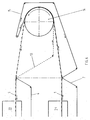
- Einzelheiten der Bandabsaugung vom Transportband und der Umlenkung des Transportbands einer Pulverbeschichtungseinheit in einer Seitenansicht;
- Fig. 2
- eine Pulverbeschichtungseinheit und nachfolgende Einbrenneinheit einer Pulverbeschichtungsanlage in einer Seitenansicht;
- Fig. 3
- Einzelheiten der Bandabsaugung für das durchlässige Band und das Stützband;
- Fig. 4
- in einer Seitenansicht Einzelheiten einer Pulverbeschichtungseinheit mit einem durchlässigen Transportband mit einem Stützband und einer Pulverabsaugung für das Absaugen von überschüssigem Pulver vom Transportband, von den Werkstücken und vom Stützband;
- Fig. 5.
- die schematische Aufsicht auf eine Pulverbeschichtungsanlage mit einer Pulverbeschichtungseinheit mit einer möglichen Anordnung der Anlagenstränge, wobei beide Anlagenstränge, parallel oder in Linie auf der gleichen Ebene liegen;
- Fig. 6
- in einer Seitenansicht eine Wendeeinrichtung für die Werkstücke mit Wendetrommel sowie innerem und äusserem Trommelband ,wobei die Anlagenstränge übereinander liegen;
- Fig. 7
- in einer Seitenansicht den Bereich der Übergabe der mit Pulver beschichteten Werkstücke vom Förderband der Pulverbeschichtungseinheit, bei der das Transportband über eine gerundete Messerkante geführt und umgelenkt wird, auf die Fördereinrichtung der nachfolgenden Einbrenneinheit;
- Fig. 8
- die Seitenansicht einer weiteren Ausführungsform des Bereichs der Übergabe der Werkstücke von der Pulverbeschichtungseinheit auf die Einbrenneinheit, bei welcher das Transportband über einen Rundstab geführt und umgelenkt wird;
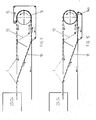
- Fig. 9
- in einer schematischen Seitenansicht Einzelheiten der Wendevorrichtung von Fig. 5, mit einer Wendeeinheit für die Werkstücke, mit einem inneren und einem äusseren Trommelband und einer Wendetrommel;
- Fig. 10
- in einer schematischen Seitenansicht Einzelheiten der Wendevorrichtung von Fig. 5 mit einer Wendeeinheit für die Werkstücke mit einem inneren Trommelband und einer magnetischen Wendetrommel.
- Fig. 11
- schematisch ein Transportband das von umlaufenden Drähten und oder Seilen gebildet wird;
- Fig. 12
- schematisch ein Transportband, das von einem maschigen Geflecht gebildet wird;
- Fig. 13
- schematisch ein Transportband, das aus ineinander gedrehten Federn gebildet ist, die quer zur Laufrichtung verlaufen,
- Fig. 13a
- zwei ineinander gedrehte Federn des Transportbandes von Fig. 13;
- Fig. 14
- ein Transportband mit Warenträger / Werkstückträger.
- Fig. 1
- Details of the belt suction from the conveyor belt and the deflection of the conveyor belt of a powder coating unit in a side view;
- Fig. 2
- a powder coating unit and subsequent stoving unit of a powder coating system in a side view;
- Fig. 3
- Details of band suction for the permeable band and the support band;
- Fig. 4
- in a side view details of a powder coating unit with a permeable conveyor belt with a support belt and a powder suction for the suction of excess powder from the conveyor belt, the workpieces and the support belt;
- Fig. 5.
- the schematic plan view of a powder coating system with a powder coating unit with a possible arrangement of the system lines, both system lines lying in parallel or in line on the same plane;
- Fig. 6
- a side view of a turning device for the workpieces with a turning drum and inner and outer drum belt, the system strands lying one above the other;
- Fig. 7
- in a side view the area of the transfer of the powder-coated workpieces from the conveyor belt of the powder coating unit, in which the conveyor belt is guided and deflected over a rounded knife edge, to the conveyor of the subsequent baking unit;
- Fig. 8
- the side view of another embodiment of the area of the transfer of the workpieces from the powder coating unit to the stoving unit, in which the conveyor belt is guided and deflected over a round rod;
- Fig. 9
- in a schematic side view details of the turning device of Figure 5, with a turning unit for the workpieces, with an inner and an outer drum belt and a turning drum.
- Fig. 10
- in a schematic side view details of the turning device of FIG. 5 with a turning unit for the workpieces with an inner drum belt and a magnetic turning drum.
- Fig. 11
- schematically a conveyor belt which is formed by circulating wires and or ropes;
- Fig. 12
- schematically a conveyor belt, which is formed by a mesh;
- Fig. 13
- schematically a conveyor belt which is formed from twisted springs which run transversely to the direction of travel,
- 13a
- two nested springs of the conveyor belt of Fig. 13;
- Fig. 14
- a conveyor belt with goods carrier / workpiece carrier.
Im Folgenden werden Verfahren und Einrichtungen sowie Einzelheiten davon
beschrieben, mit denen gestanzte, gebogene, gedrückte, gezogene,
geschweisste, gegossene, gespritzte oder gesinterte oder anderweitig geformte
Werkstücke 1 einseitig oder allseitig mit Pulver beschichtet werden. Die
Einrichtungen eignen sich in erster Linie für kleinere Werkstücke 1 die in
grösseren Stückzahlen pulverbeschichtet werden müssen. Mit diesen
Einrichtungen müssen die Werkstücke 1 nicht aufgehängt werden, sondern sie
können in einfacher Weise automatisch oder von Hand auf ein
Transportsystem 2 gelegt werden und durchlaufen anschliessend automatisch
mindestens einen Pulverapplikationsbereich 5 und einen Einbrennofen 19.The following are procedures and facilities, as well as details thereof
described with which punched, curved, pressed, drawn,
welded, cast, sprayed or sintered or otherwise shaped
Die Positionen 2, 5 und 19 werden im folgenden auch als Anlagenstrang
bezeichnet. Im Bereich der Pulverapplikation ist das Transportband im
Gegensatz zu bekannten Anlagen luft- und pulverdurchlässig gestaltet. Die auf
dem luft- und pulverdurchlässigen Transportband 4 liegenden Werkstücke 1
werden beim Durchlaufen des Pulverapplikationsbereiches von oben und/oder
von der Seite mit z.B. elektrostatischer Pulversprühpistolen besprüht. Das
Pulver lagert sich auf dem Werkstück 1 und dem luft- und pulverdurchlässigen
Transportband 4 ab und ein Teil des Pulvers gelangt durch das durchlässige
Band nach unten und in gelangt in den trichterförmigen Kabinenunterteil, von
wo des Pulver über Zyklone oder Filter zurückgewonnen wird.
Das mit Pulver behaftete, luft- und pulverdurchlässige Transportband 4
bestückt mit den ebenfalls pulverbehafteten Werkstücken 1 wird nun vor der
Umlenkung 10, 11 und 12 ausserhalb des Sprühbereichs mit einem
Saugbalken 6 von unten von Pulver gereinigt und das abgesaugte Pulver wird
ebenfalls mit Zyklon oder Filter zurückgewonnen. Dadurch werden das luft- und
pulverdurchlässige Transportband 4 sowie aufliegende Kanten oder Flächen
der Werkstücke 1 grossenteils von überschüssigem Pulver befreit, bevor die
Werkstücke 1 auf das wärmebeständige Transportband 6 des anschliessenden
Einbrennofens 19 übergeben werden. Das luft- und pulverdurchlässige
Transportband 4 wird mit Vorteil im Rücklauf in einer Nachreinigungseinheit 20
von etwa noch verbleibenden Pulverresten befreit (Fig. 1).The air and powder
Die Praxis hat gezeigt dass es in gewissen Fällen vorteilhaft ist, das luft- und
pulverdurchlässige Transportband 4 im Pulverapplikationsbereich durch ein
undurchlässiges Stützband 8 zu stützen (Fig. 2) und die Luftströmung seitlich
abzuleiten statt nach unten durch das luft- und pulverdurchlässige
Transportband 4. Dadurch lagert sich mehr Pulver an den senkrecht zum
Transportband 4 liegenden Flächen der Werkstücke 1 ab. Dies ist vor allem bei
hohen Werkstücken 1 vorteilhaft.Practice has shown that it is advantageous in certain cases that the air and
powder
Bei allseitiger Beschichtung muss das Werkstück 1 nach dem ersten
Beschichtungsvorgang (Pulverapplikation, Einbrennen und Kühlen) gewendet
werden und durchläuft nochmals den gleichen oder einen anschliessenden
zweiten Anlagenstrang, der gleich oder ähnlich gestaltet ist. Dies kann in zwei
übereinander liegenden Anlagensträngen 21; 22 erfolgen, wobei die
Werkstücke 1 zwischen den beiden Anlagensträngen 21, 22 mittels einer
Wendetrommel 14 automatisch gewendet werden, indem die Werkstücke
zwischen einem inneren Trommelband 13 und einem äusseren Trommelband
15 eingeklemmt und um die Wendetrommel 14 geführt werden (Fig. 6).With all-round coating, the
Sollen die beiden Anlagenstränge auf der gleichen horizontalen Ebene
angeordnet werden, wie in Fig. 5 gezeigt, so werden die Werkstücke 1 nach
dem ersten Anlagenstrang 23 über ein erstes 90 Grad Kurvenband 16 zur
Wendetrommel 14 gefahren, die im gezeigten Beispiel rechtwinklig zu den
beiden Anlagensträngen angeordnet ist, und anschliessend auf ein zweites
Kurvenband 17 von dem aus die Werkstücke 1 auf einen parallel oder in Linie
liegenden zweiten Anlagenstrang 24 gefahren werden wobei, die durch die
Wendetrommel verursachten Höhenunterschiede vor oder nach den
Kurvenbändern 16, 17 kompensiert werden können (Fig. 9 und 10)
Mit den gezeigten Vorrichtung und dem beschriebenen Verfahren müssen zu
beschichtende Werkstücke 1 nicht aufgehängt werden und können trotzdem
allseitig beschichtet werden. Es eignet sich daher vor allem dort wo sehr
grosse Mengen von gleichen oder ähnlichen, kleinen Werkstücken beschichtet
werden müssen, z.B. Beschläge, Auswuchtgewichte, Ferrit-Ringe, Schrauben,
Scheiben etc. Das Entlacken von Gehängen entfällt bei diesem Verfahren.
Werkzeuge werden im Normalfall nicht gebraucht.The two lines of equipment should be on the same horizontal level
are arranged, as shown in Fig. 5, the
Fig. 11, Fig. 12 und Fig. 13 zeigen verschiedene Transportbänder. Das
Transportband von Fig. 11 wird von Drähten oder Seilen 411 gebildet, welche
um Rollen 412 bzw. gerundeten Messer 413 laufen und geführt sind. Das
Transportband von Fig. 12 ist ein Geflecht 421, das um Rollen 422 bzw.
gerundete Messer 413 laufen. Das Transportband von Fig. 13 schliesslich wird
von ineinander gedrehten Federn 431 gebildet, die quer zur Transportrichtung
verlaufen und um Rollen 432, bzw. gerundete Messer 433 laufen. Es versteht
sich, dass die Wahl von Rollen und Messern beliebig sein kann. Fig. 13a zeigt
in einer Vergrösserung zwei Federn 431' und 431'', die ineinander gedreht
sind. Das Transportband 431 ist derart aus Federn aufgebaut.
Die Seile, Drähte, Geflechte und Federn ,d.h. die Werkstoffe, aus denen diese
gefertigt sind, sind mit Vorteil elektrisch leitend. Der Werkstoff kann als solcher
leitend, z.B. ein Metall sein. Das Transportband 411, 421, 431 kann aber auch
aus nicht leitendem Werkstoff, wie beispielsweise einem Kunststoff gefertigt
sein, der mit einer Schicht aus leitendem Material beschichtet ist..11, 12 and 13 show different conveyor belts. The
11 is formed by wires or
Der Warenträger 25 auf dem Transportband (4) dient wie in Fig. 14 dargestellt,
zur Aufnahme der zu beschichtenden Werkstücke (1) bzw. zum Abstützen oder
Positionieren der Werkstücke. Das Umlenken des Transportbandes erfolgt
auch hier über Rollen und/oder gerundete Messer.The
Claims (10)
Applications Claiming Priority (4)
| Application Number | Priority Date | Filing Date | Title |
|---|---|---|---|
| CH6/97 | 1996-12-23 | ||
| CH317496 | 1996-12-23 | ||
| CH3174/96 | 1996-12-23 | ||
| CH697 | 1996-12-23 |
Publications (2)
| Publication Number | Publication Date |
|---|---|
| EP0858841A2 true EP0858841A2 (en) | 1998-08-19 |
| EP0858841A3 EP0858841A3 (en) | 1999-03-10 |
Family
ID=25683240
Family Applications (1)
| Application Number | Title | Priority Date | Filing Date |
|---|---|---|---|
| EP97811015A Withdrawn EP0858841A3 (en) | 1996-12-23 | 1997-12-22 | Powder coating unit, conveyor for such a unit and powder coating installation with the same |
Country Status (1)
| Country | Link |
|---|---|
| EP (1) | EP0858841A3 (en) |
Cited By (11)
| Publication number | Priority date | Publication date | Assignee | Title |
|---|---|---|---|---|
| WO2001085357A1 (en) * | 2000-05-12 | 2001-11-15 | Cefla Soc. Coop. A R.L. | Method and apparatus for the horizontal painting of wood products |
| EP1243340A2 (en) | 2001-03-22 | 2002-09-25 | CEFLA Soc. Coop. a r.l. | Machine for the horizontal painting of products |
| WO2003072265A1 (en) * | 2002-02-28 | 2003-09-04 | S.I.P.A. Societa' Industrializzazione Progettazione Automazione S.P.A. | A device and method for coating containers |
| EP1388373A3 (en) * | 2002-08-07 | 2006-08-02 | CEFLA Soc. Coop. a r.l. | Equipment for preparing for electrostatic painting three-dimensional articles with a predominantly flat extension |
| CN100411751C (en) * | 2003-06-26 | 2008-08-20 | 阿耐思特岩田株式会社 | Automatic rotary coating method and coating apparatus |
| ITBO20120077A1 (en) * | 2012-02-20 | 2013-08-21 | Cefla Coop | METHOD AND EQUIPMENT FOR PAINT FINISH OF PREVALENT EXTENSION OF FLAT PAINT |
| EP3120935A3 (en) * | 2015-08-20 | 2017-02-22 | Tianhe (Baotou) Advanced Tech Magnet Co., Ltd. | Spraying device and use thereof |
| EP3401022A1 (en) * | 2017-05-10 | 2018-11-14 | Dürr Systems AG | Conveyor, coating apparatus comprising a conveyor and method of operating the same |
| CN108855673A (en) * | 2018-08-06 | 2018-11-23 | 安徽星光标识系统有限公司 | High efficiency cutting, spraying, drying equipment for cystosepiment production |
| IT201800009428A1 (en) * | 2018-10-15 | 2020-04-15 | Elmag Spa | Machine for painting pieces and relative method. |
| CN113318888A (en) * | 2021-08-02 | 2021-08-31 | 山东科技职业学院 | Upset spraying device |
Citations (1)
| Publication number | Priority date | Publication date | Assignee | Title |
|---|---|---|---|---|
| EP0405164B1 (en) | 1989-05-31 | 1995-12-13 | SFB Spezialfilter und Anlagenbau AG | Installation and method for making coated flat pieces, in particular flat metal sheets |
Family Cites Families (6)
| Publication number | Priority date | Publication date | Assignee | Title |
|---|---|---|---|---|
| GB1492092A (en) * | 1976-06-03 | 1977-11-16 | Plastic Coatings Ltd | Method and apparatus for sintering plastics coatings applied to articles |
| US4495217A (en) * | 1982-04-19 | 1985-01-22 | Schrum Timothy J | Method for applying powdered coatings |
| JPS6138653A (en) * | 1984-07-31 | 1986-02-24 | Matsuo Sangyo Kk | Electrostatic painting booth provided with both filter band and wire-net conveyor |
| DE3631270A1 (en) * | 1986-09-13 | 1988-03-24 | Kopperschmidt Mueller & Co | DEVICE FOR SPRAY COATING WORKPIECES |
| US5264037A (en) * | 1990-02-28 | 1993-11-23 | Blodgett & Blodgett, P.C. | Powder coating system |
| JP3355446B2 (en) * | 1993-12-07 | 2002-12-09 | 日本パーカライジング株式会社 | Electrostatic powder coating method and apparatus |
-
1997
- 1997-12-22 EP EP97811015A patent/EP0858841A3/en not_active Withdrawn
Patent Citations (1)
| Publication number | Priority date | Publication date | Assignee | Title |
|---|---|---|---|---|
| EP0405164B1 (en) | 1989-05-31 | 1995-12-13 | SFB Spezialfilter und Anlagenbau AG | Installation and method for making coated flat pieces, in particular flat metal sheets |
Cited By (13)
| Publication number | Priority date | Publication date | Assignee | Title |
|---|---|---|---|---|
| WO2001085357A1 (en) * | 2000-05-12 | 2001-11-15 | Cefla Soc. Coop. A R.L. | Method and apparatus for the horizontal painting of wood products |
| EP1243340A2 (en) | 2001-03-22 | 2002-09-25 | CEFLA Soc. Coop. a r.l. | Machine for the horizontal painting of products |
| WO2003072265A1 (en) * | 2002-02-28 | 2003-09-04 | S.I.P.A. Societa' Industrializzazione Progettazione Automazione S.P.A. | A device and method for coating containers |
| EP1388373A3 (en) * | 2002-08-07 | 2006-08-02 | CEFLA Soc. Coop. a r.l. | Equipment for preparing for electrostatic painting three-dimensional articles with a predominantly flat extension |
| CN100411751C (en) * | 2003-06-26 | 2008-08-20 | 阿耐思特岩田株式会社 | Automatic rotary coating method and coating apparatus |
| ITBO20120077A1 (en) * | 2012-02-20 | 2013-08-21 | Cefla Coop | METHOD AND EQUIPMENT FOR PAINT FINISH OF PREVALENT EXTENSION OF FLAT PAINT |
| EP3120935A3 (en) * | 2015-08-20 | 2017-02-22 | Tianhe (Baotou) Advanced Tech Magnet Co., Ltd. | Spraying device and use thereof |
| EP3401022A1 (en) * | 2017-05-10 | 2018-11-14 | Dürr Systems AG | Conveyor, coating apparatus comprising a conveyor and method of operating the same |
| CN108855673A (en) * | 2018-08-06 | 2018-11-23 | 安徽星光标识系统有限公司 | High efficiency cutting, spraying, drying equipment for cystosepiment production |
| IT201800009428A1 (en) * | 2018-10-15 | 2020-04-15 | Elmag Spa | Machine for painting pieces and relative method. |
| EP3639931A1 (en) * | 2018-10-15 | 2020-04-22 | Elmag S.P.A. | Device for coating and method thereof |
| CN113318888A (en) * | 2021-08-02 | 2021-08-31 | 山东科技职业学院 | Upset spraying device |
| CN113318888B (en) * | 2021-08-02 | 2021-11-12 | 山东科技职业学院 | Upset spraying device |
Also Published As
| Publication number | Publication date |
|---|---|
| EP0858841A3 (en) | 1999-03-10 |
Similar Documents
| Publication | Publication Date | Title |
|---|---|---|
| EP2094593B1 (en) | Workpiece carrier for conveying a workpiece to be painted | |
| DE10115376B4 (en) | Plant for powder coating of objects | |
| EP0858841A2 (en) | Powder coating unit, conveyor for such a unit and powder coating installation with the same | |
| EP1745858A2 (en) | Coating process and corresponding apparatus | |
| EP3186013B1 (en) | Device for treating objects | |
| EP0745001B1 (en) | Painting process and spray painting device suitable for implementing the process | |
| DE102010032144A1 (en) | Treatment unit and facility for surface treatment of objects | |
| DE4217615A1 (en) | METHOD FOR COATING WORKPIECES WITH COLOR BY ELECTROLYTIC DEPOSITION | |
| DE3340510C2 (en) | Electrostatic powder coating device | |
| EP2866916B1 (en) | Filter device for the dry separation of adhesive particles | |
| WO2007131752A1 (en) | Method for carrying out a cleaning process and device for carrying out said method | |
| DE4430542C2 (en) | Transport system for transporting helical compression springs through a shot peening system | |
| EP0634225B1 (en) | Device for discharging the walls of a plastic booth | |
| EP3147033B1 (en) | Device for removing the overspray from a chamber | |
| EP1378294A2 (en) | Powder coating installation | |
| DE1190368B (en) | Device for the electrostatic application of liquid to essentially flat workpiece surfaces | |
| DE2323572A1 (en) | SPRAY COATING DEVICE | |
| EP0382945B1 (en) | Method for coating objects | |
| DE4430749A1 (en) | Powder recuperation device for powder application plant | |
| DE19819486B4 (en) | Carrier assembly for painting and painting | |
| DE10231503A1 (en) | Process for coating, in particular painting objects | |
| DE102005032713B4 (en) | Method and device for treating a machined workpiece and conveying means | |
| DE2535584C2 (en) | Conveyor device, in particular for ceramic objects | |
| DE19704421A1 (en) | Apparatus for forming bundles from loops of rolled wire | |
| DE19511900C2 (en) | Device for electro-dip painting |
Legal Events
| Date | Code | Title | Description |
|---|---|---|---|
| PUAI | Public reference made under article 153(3) epc to a published international application that has entered the european phase |
Free format text: ORIGINAL CODE: 0009012 |
|
| AK | Designated contracting states |
Kind code of ref document: A2 Designated state(s): AT BE CH DE DK LI |
|
| AX | Request for extension of the european patent |
Free format text: AL;LT;LV;MK;RO;SI |
|
| PUAL | Search report despatched |
Free format text: ORIGINAL CODE: 0009013 |
|
| AK | Designated contracting states |
Kind code of ref document: A3 Designated state(s): AT BE CH DE DK ES FI FR GB GR IE IT LI LU MC NL PT SE |
|
| AX | Request for extension of the european patent |
Free format text: AL;LT;LV;MK;RO;SI |
|
| AKX | Designation fees paid | ||
| 17P | Request for examination filed |
Effective date: 19990910 |
|
| RBV | Designated contracting states (corrected) |
Designated state(s): AT BE CH DE DK LI |
|
| RBV | Designated contracting states (corrected) |
Designated state(s): DE ES FR GB IT |
|
| 17Q | First examination report despatched |
Effective date: 20020117 |
|
| GRAH | Despatch of communication of intention to grant a patent |
Free format text: ORIGINAL CODE: EPIDOS IGRA |
|
| RTI1 | Title (correction) |
Free format text: POWDER COATING UNIT AND POWDER COATING INSTALLATION WITH THE SAME |
|
| GRAH | Despatch of communication of intention to grant a patent |
Free format text: ORIGINAL CODE: EPIDOS IGRA |
|
| GRAH | Despatch of communication of intention to grant a patent |
Free format text: ORIGINAL CODE: EPIDOS IGRA |
|
| RAP1 | Party data changed (applicant data changed or rights of an application transferred) |
Owner name: SEILER, DANIEL |
|
| RIN1 | Information on inventor provided before grant (corrected) |
Inventor name: SEILER, DANIEL |
|
| STAA | Information on the status of an ep patent application or granted ep patent |
Free format text: STATUS: THE APPLICATION IS DEEMED TO BE WITHDRAWN |
|
| 18D | Application deemed to be withdrawn |
Effective date: 20030701 |