EP0858571B1 - Tragvorrichtung mit einstellbarer neigung und insbesondere mit haltung in horizontaler stellung - Google Patents
Tragvorrichtung mit einstellbarer neigung und insbesondere mit haltung in horizontaler stellung Download PDFInfo
- Publication number
- EP0858571B1 EP0858571B1 EP96934978A EP96934978A EP0858571B1 EP 0858571 B1 EP0858571 B1 EP 0858571B1 EP 96934978 A EP96934978 A EP 96934978A EP 96934978 A EP96934978 A EP 96934978A EP 0858571 B1 EP0858571 B1 EP 0858571B1
- Authority
- EP
- European Patent Office
- Prior art keywords
- jacks
- upright
- plate
- inclination
- pivot pin
- Prior art date
- Legal status (The legal status is an assumption and is not a legal conclusion. Google has not performed a legal analysis and makes no representation as to the accuracy of the status listed.)
- Expired - Lifetime
Links
- 230000005484 gravity Effects 0.000 claims description 5
- 230000000712 assembly Effects 0.000 claims description 2
- 238000000429 assembly Methods 0.000 claims description 2
- 238000010276 construction Methods 0.000 description 2
- 230000007246 mechanism Effects 0.000 description 2
- 238000010586 diagram Methods 0.000 description 1
- 239000006185 dispersion Substances 0.000 description 1
- 238000006073 displacement reaction Methods 0.000 description 1
- 238000009434 installation Methods 0.000 description 1
- 239000007788 liquid Substances 0.000 description 1
- 238000012423 maintenance Methods 0.000 description 1
- QSHDDOUJBYECFT-UHFFFAOYSA-N mercury Chemical compound [Hg] QSHDDOUJBYECFT-UHFFFAOYSA-N 0.000 description 1
- 229910052753 mercury Inorganic materials 0.000 description 1
- 238000004321 preservation Methods 0.000 description 1
- 230000035945 sensitivity Effects 0.000 description 1
- 238000004904 shortening Methods 0.000 description 1
Images


Classifications
-
- F—MECHANICAL ENGINEERING; LIGHTING; HEATING; WEAPONS; BLASTING
- F16—ENGINEERING ELEMENTS AND UNITS; GENERAL MEASURES FOR PRODUCING AND MAINTAINING EFFECTIVE FUNCTIONING OF MACHINES OR INSTALLATIONS; THERMAL INSULATION IN GENERAL
- F16M—FRAMES, CASINGS OR BEDS OF ENGINES, MACHINES OR APPARATUS, NOT SPECIFIC TO ENGINES, MACHINES OR APPARATUS PROVIDED FOR ELSEWHERE; STANDS; SUPPORTS
- F16M11/00—Stands or trestles as supports for apparatus or articles placed thereon ; Stands for scientific apparatus such as gravitational force meters
- F16M11/02—Heads
- F16M11/18—Heads with mechanism for moving the apparatus relatively to the stand
-
- F—MECHANICAL ENGINEERING; LIGHTING; HEATING; WEAPONS; BLASTING
- F16—ENGINEERING ELEMENTS AND UNITS; GENERAL MEASURES FOR PRODUCING AND MAINTAINING EFFECTIVE FUNCTIONING OF MACHINES OR INSTALLATIONS; THERMAL INSULATION IN GENERAL
- F16M—FRAMES, CASINGS OR BEDS OF ENGINES, MACHINES OR APPARATUS, NOT SPECIFIC TO ENGINES, MACHINES OR APPARATUS PROVIDED FOR ELSEWHERE; STANDS; SUPPORTS
- F16M11/00—Stands or trestles as supports for apparatus or articles placed thereon ; Stands for scientific apparatus such as gravitational force meters
- F16M11/02—Heads
- F16M11/04—Means for attachment of apparatus; Means allowing adjustment of the apparatus relatively to the stand
- F16M11/06—Means for attachment of apparatus; Means allowing adjustment of the apparatus relatively to the stand allowing pivoting
- F16M11/10—Means for attachment of apparatus; Means allowing adjustment of the apparatus relatively to the stand allowing pivoting around a horizontal axis
Definitions
- this provision known has various disadvantages including the main relate to positioning games which, while weak, are too important to ensure positioning precise and stable camera.
- this device known which only allows to maintain or restore its horizontality is of complicated construction while the arrangement of cylinders and upright connected in an articulated manner to the plates does not allow an easy installation inclinometers and electronic circuits to be able to then have sufficient and clear space for fixing the support on the base and for fixing a camera on this support.
- the object of the present invention is in particular to remedy these drawbacks and to this end concerns a support device of this type, characterized in that the cylinders and the upright are rigidly fixed on one of the trays, said lower tray, and are connected to each other tray, called upper tray, by a set articulation comprising a universal joint and a pivot axis, each pivot axis being located parallel to the opposite side of the triangle delimited on this plate.
- the three sets of universal joint and pivot axis are the same.
- the gimbals are arranged on the end side of the cylinders and the upright while the pivot axes are arranged on the side of the upper plate.
- the device has two double inclinometers arranged each in the supply circuit of one of the cylinders, this circuit comprising a contactor assembly sensitive to the gravity, suitable for adjusting the inclination of the device in its upright or inverted position.
- the cylinders include mechanical, manual adjustment means, of their length.
- the present invention therefore aims to realization of a support device which is of adjustable inclination and which can validly be used to support a camera.
- This support device has for this purpose zero play in the three directions from space.
- This device is also of simple construction and can be used either in an upright position or in an inverted position, the inclination being adjustable in both directions, either manually or automatically. In the latter case of automatic adjustment, the device maintains the horizontality of the support relative to on the ground.
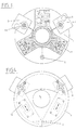
- the device comprises a lower plate 1 and an upper plate 2 which are connected by two jacks electrical 3 and 4 and by a constant length upright 5.
- cylinders and upright 3, 4 and 5 together define a triangle, preferably an equilateral triangle, and are rigidly fixed, perpendicularly, to the lower plate while they are connected to the upper plate by three articulation sets 6.
- These articulation assemblies which are identical include a cardan joint 6 1 and a hinge pin 6 2 .
- the gimbal 6 1 is supported by one end 3 1 , 4 1 (not shown) of the jacks and 5 1 of the upright while the hinge pins 6 2 are mounted on the upper plate 2 and define the vertices of the aforementioned triangular structure .
- These axes 6 2 are each arranged parallel to the opposite side 7 of this triangular arrangement.
- the articulation axes 6 2 are arranged relative to the gimbal 6 1 so that the parts 8 which connect the axes to the gimbals are inclined at an angle ⁇ relative to the vertical axis x of the device (see figure 2).
- This arrangement also makes it possible to reduce the bulk to the interior of the volume delimited by the two trays to facilitate the establishment of the mechanisms ensuring the functioning of the support, as well as mechanisms supporting or supported by it device.
- the manual adjustment of the tilt of the upper plate 2 or the automatic adjustment to maintain its horizontality is obtained from electric cylinders 2 which include a manual adjustment button 9 of the motorization arranged on the output axis of the gear motor 10, this axis also comprising a pinion 11 which meshes with a second pinion 12 secured to a nut 13 engaged on the rod threaded 14 kept fixed in rotation.
- Spirit levels 15, preferably three in number, are arranged at the periphery of the upper plate 2 between the jacks 3, 4 and the upright 5 in order to facilitate viewing of the horizontality, in particular during manual adjustment.
- two sensitive double monoaxial inclinometers 16 are provided. under gravity, arranged each time between a jack and the upright, the working axis 16 1 of these double inclinometers being each time parallel to the adjacent side 7 of the above-mentioned triangular structure.
- These double inclinometers which are fixed under the underside of the upper plate 2 each comprise two elements sensitive to gravity, known in themselves and which produce a signal as a function of the inclination in measuring the conductivity of a liquid by a magnetic dispersion field in order to determine the filling level first and then, according to a differential mode, tilt angle.
- the electronic circuit ensuring the control of each of the jacks 3 from one of the double inclinometers 16 is fixed on the upper face of the lower plate 1 by means of a printed circuit 17 and occupies a triangular arrangement between the jacks 3 , 4 and the amount 5 (see Figure 3) so as to achieve a rational layout, mechanically protected in the space of the support device and clearing the central orifice 1 1 of the lower plate 1 with the help of which the support device adapts fixedly, for example to a base.
- the supply of this circuit will preferably be carried out from batteries.
- the electronic control circuit of each motor 10 of the cylinders 3 and 4 from the inclinometers 16 1 and 16 2 of each double inclinometer 16, comprises a reversing contactor 19 operating by gravity, preferably of the mercury contact type, which is connected to each of the inclinometer elements 16 1 and 16 2 in order to switch one of them according to whether the support device occupies a normal position (the upper plate being arranged at the top), or an inverted position (the upper plate being placed under the lower plate).
- This circuit also includes a reversing contactor 20 intended either to switch on the inclinometer elements 16 1 and 16 2 by means of the contactor 19 to ensure automatic maintenance of the horizontality of the support, or to switch reversing contactors 21 and 22 in order to allow the power to the motor 10 of the jack concerned, either to ensure the extension of the jack (contactor 21), or to ensure its shortening (contactor 22).
- a reversing contactor 20 intended either to switch on the inclinometer elements 16 1 and 16 2 by means of the contactor 19 to ensure automatic maintenance of the horizontality of the support, or to switch reversing contactors 21 and 22 in order to allow the power to the motor 10 of the jack concerned, either to ensure the extension of the jack (contactor 21), or to ensure its shortening (contactor 22).
- These contactors 21 and 22 are preferably constituted by push buttons.
- the inverter 20 When manual operation is selected by the inverter 20, the actuation of the push buttons 21 or 22 then supplies the motor 10 in a direction of rotation, or the opposite direction, via a stage 23 engine control and through a comparator 24.
- the motor 10 is supplied, in this case, via the motor controller 23 and a window comparator 25 from one or the other of the inclinometers 16 1 , 16 2 .
- inclinometers are also connected to potentiometer devices 26 and 27 for adjusting on the one hand the zero position, on the other hand the sensitivity of the device.
- the reference potentials of these comparators 24 and 25 are determined by a divider bridge comprising four resistors 28, 29, 30 and 31.
- the device according to the invention allows therefore manual and mechanical adjustment of the inclination by buttons 9, manual and electrical adjustment of tilt by contactors 21 and 22 and an adjustment automatic with horizontality maintained by actuation of the reversing contactor 20.
- the device according to the invention will include also a ball contactor shown schematically at 30 in the figure 5, this ball contactor being intended to prohibit power to motor 10 one way or the other when the inclination of the upper plate relative to the lower plate exceeds a determined value and, for example ⁇ 10 °, beyond which the cylinders do not allow more to catch up on horizontality.
Landscapes
- Engineering & Computer Science (AREA)
- General Engineering & Computer Science (AREA)
- Mechanical Engineering (AREA)
- Details Of Measuring And Other Instruments (AREA)
- Vehicle Body Suspensions (AREA)
- Attitude Control For Articles On Conveyors (AREA)
- Accommodation For Nursing Or Treatment Tables (AREA)
- Automatic Assembly (AREA)
- Spinning Or Twisting Of Yarns (AREA)
- Accessories Of Cameras (AREA)
- Shaping Of Tube Ends By Bending Or Straightening (AREA)
Claims (8)
- Trägervorrichtung mit einstellbarer Neigung und insbesondere mit Erhaltung ihrer Horizontalität, die zwei übereinander angeordnete Platten (1 und 2) aufweist, die durch zwei Zylinder (3 und 4) mit elektrischer Steuerung und einstellbarer Länge und einen Pfosten mit konstanter Länge verbunden sind, die an diesen Platten die Spitzen von Dreiecken bilden, dadurch gekennzeichnet, dass die Zylinder und der Pfosten an einer der Platten (1), untere Platte genannt, starr befestigt und mit der anderen Platte (2), obere Platte genannt, über eine Gelenkeinheit (6) verbunden sind, die ein Kardangelenk (61) und einen Schwenkbolzen (62) umfasst, wobei jeder Schwenkbolzen (62) zur entgegengesetzten Seite (7) des abgegrenzten Dreiecks auf dieser Platte parallel liegt, und dass für jede Gelenkeinheit entweder das Kardangelenk oder der Schwenkbolzen an der oberen Platte angebracht ist.
- Vorrichtung nach Anspruch 1, dadurch gekennzeichnet, dass die drei Gelenkeinheiten (6) mit Kardangelenk und Schwenkbolzen identisch sind.
- Vorrichtung nach einem der vorhergehenden Ansprüche, dadurch gekennzeichnet, dass sie zwei doppelte (161, 162) Neigungsmesser (16) aufweist, die jeweils im Speisestromkreis eines der Zylinder (3, 4) angeordnet sind, wobei dieser Stromkreis eine für die Schwere empfindliche Schaltereinheit (19) aufweist, die geeignet ist die Einstellung der Neigung der Vorrichtung in ihre gerade oder gekippte Position sicherzustellen.
- Vorrichtung nach dem vorhergehenden Anspruch, dadurch gekennzeichnet, dass der elektrische Speisestromkreis der Zylinder (3, 4) einen Wendeschalter (20) aufweist, um Neigungsmesser in/außerhalb des Stromskreises zu setzen, und umgekehrt, um zwei Schalter (21 und 22) für die direkte Versorgung der Zylinder außerhalb/in den Stromkreis zu setzen.
- Vorrichtung nach einem der vorhergehenden Ansprüche, dadurch gekennzeichnet, dass die Zylinder (3, 4) Mittel (9) zur mechanischen Einstellung ihrer Länge von Hand aufweisen.
- Vorrichtung nach Anspruch 3, dadurch gekennzeichnet, dass die elektronische Versorgungsschaltung der Zylinder an der unteren Platte (1) befestigt und mit den Neigungsmessern (16), die an der oberen Platte befestigt sind, durch leitende Verbindungen (18) verbunden ist, die im Inneren des Pfostens (5) mit konstanter Höhe angeordnet sind.
- Vorrichtung nach einem der vorhergehenden Ansprüche, dadurch gekennzeichnet, dass der elektrische Speisestromkreis der Zylinder (3, 4) an der Oberseite der unteren Platte (1) um eine zentrale Bohrung (11) dieser Platte herum und zwischen den Zylindern und dem Pfosten befestigt ist.
- Vorrichtung nach einem der vorhergehenden Ansprüche, dadurch gekennzeichnet, dass der Schwenkbolzen (62) und das Kardangelenk (61) jeder Gelenkeinheit (6) über ein Teil (8) verbunden sind, wobei diese Teile zur Achse (X-X) der Vorrichtung hin geneigt sind.
Applications Claiming Priority (3)
| Application Number | Priority Date | Filing Date | Title |
|---|---|---|---|
| FR9513792A FR2741421B1 (fr) | 1995-11-21 | 1995-11-21 | Dispositif de support a inclinaison reglable et notamment a conservation de son horizontalite |
| FR9513792 | 1995-11-21 | ||
| PCT/FR1996/001677 WO1997019291A1 (fr) | 1995-11-21 | 1996-10-25 | Dispositif de support a inclinaison reglable et notamment a conservation de son horizontalite |
Publications (2)
| Publication Number | Publication Date |
|---|---|
| EP0858571A1 EP0858571A1 (de) | 1998-08-19 |
| EP0858571B1 true EP0858571B1 (de) | 2001-08-22 |
Family
ID=9484769
Family Applications (1)
| Application Number | Title | Priority Date | Filing Date |
|---|---|---|---|
| EP96934978A Expired - Lifetime EP0858571B1 (de) | 1995-11-21 | 1996-10-25 | Tragvorrichtung mit einstellbarer neigung und insbesondere mit haltung in horizontaler stellung |
Country Status (8)
| Country | Link |
|---|---|
| EP (1) | EP0858571B1 (de) |
| JP (1) | JP2000500555A (de) |
| AT (1) | ATE204633T1 (de) |
| AU (1) | AU7308796A (de) |
| DE (1) | DE69614703T2 (de) |
| FR (1) | FR2741421B1 (de) |
| MA (1) | MA24003A1 (de) |
| WO (1) | WO1997019291A1 (de) |
Families Citing this family (9)
| Publication number | Priority date | Publication date | Assignee | Title |
|---|---|---|---|---|
| EP1207369A1 (de) * | 2000-11-17 | 2002-05-22 | Leica Geosystems AG | Sensorträger zur Durchführung zentrierter Aufstellungen |
| US8256169B2 (en) | 2009-03-20 | 2012-09-04 | Northern States Metals Company | Support system for solar panels |
| US8240109B2 (en) | 2009-03-20 | 2012-08-14 | Northern States Metals Company | Support system for solar panels |
| US8316590B2 (en) | 2009-03-20 | 2012-11-27 | Northern States Metals Company | Support system for solar panels |
| WO2010141740A2 (en) | 2009-06-05 | 2010-12-09 | First Solar, Inc. | Photovoltaic module ground mount |
| WO2012018360A1 (en) | 2010-08-06 | 2012-02-09 | First Solar, Inc. | Folding mount for photovoltaic modules |
| US8839573B2 (en) | 2011-02-11 | 2014-09-23 | Northern States Metals Company | Spring clip |
| US9303663B2 (en) | 2013-04-11 | 2016-04-05 | Northern States Metals Company | Locking rail alignment system |
| CN112253935B (zh) * | 2020-11-09 | 2022-05-13 | 无锡职业技术学院 | 一种千斤顶支撑座 |
Family Cites Families (5)
| Publication number | Priority date | Publication date | Assignee | Title |
|---|---|---|---|---|
| US3215391A (en) * | 1964-06-29 | 1965-11-02 | Collins Radio Co | Positioning device continuous in azimuth and elevation using multiple linear drives |
| DE2345894A1 (de) * | 1973-09-12 | 1975-03-20 | Spitzer Kg Ludwig Sen | Vorrichtung zur nivellierung von messeinrichtungen, insbesondere wiegevorrichtungen an fahrzeugen |
| US4370813A (en) * | 1979-06-05 | 1983-02-01 | Burniski Edward W | Automatic self-leveling instrument mount |
| CA1255616A (en) * | 1983-06-02 | 1989-06-13 | Ken-Ichi Yoshida | Positioning mechanism |
| GB2250109A (en) * | 1990-10-29 | 1992-05-27 | Martin Moore | Level control system |
-
1995
- 1995-11-21 FR FR9513792A patent/FR2741421B1/fr not_active Expired - Fee Related
-
1996
- 1996-10-25 AU AU73087/96A patent/AU7308796A/en not_active Abandoned
- 1996-10-25 EP EP96934978A patent/EP0858571B1/de not_active Expired - Lifetime
- 1996-10-25 JP JP9519428A patent/JP2000500555A/ja active Pending
- 1996-10-25 AT AT96934978T patent/ATE204633T1/de not_active IP Right Cessation
- 1996-10-25 WO PCT/FR1996/001677 patent/WO1997019291A1/fr not_active Ceased
- 1996-10-25 DE DE69614703T patent/DE69614703T2/de not_active Expired - Fee Related
- 1996-11-07 MA MA24388A patent/MA24003A1/fr unknown
Also Published As
| Publication number | Publication date |
|---|---|
| AU7308796A (en) | 1997-06-11 |
| DE69614703T2 (de) | 2002-06-20 |
| ATE204633T1 (de) | 2001-09-15 |
| DE69614703D1 (de) | 2001-09-27 |
| WO1997019291A1 (fr) | 1997-05-29 |
| FR2741421B1 (fr) | 1997-12-26 |
| EP0858571A1 (de) | 1998-08-19 |
| MA24003A1 (fr) | 1997-07-01 |
| FR2741421A1 (fr) | 1997-05-23 |
| JP2000500555A (ja) | 2000-01-18 |
Similar Documents
| Publication | Publication Date | Title |
|---|---|---|
| EP0858571B1 (de) | Tragvorrichtung mit einstellbarer neigung und insbesondere mit haltung in horizontaler stellung | |
| EP0132179B1 (de) | Operationstisch | |
| FR2540799A1 (fr) | Dispositif de propulsion pour echafaudages de travail | |
| EP2433085B1 (de) | Dreidimensionale messvorrichtung | |
| EP0379448B1 (de) | Kran mit anhebbarem Ausleger und mit einer Ausleger-Rückstossvorrichtung | |
| WO1996007513A1 (fr) | Systeme telescopique | |
| FR2609797A1 (fr) | Niveau a faisceau laser | |
| FR2668103A1 (fr) | Mecanisme de reglage d'attitude pour appareil de manutention sur camion. | |
| FR2601435A1 (fr) | Pied en particulier pour terminaux d'affichage | |
| EP0119910B1 (de) | Schwenkverfahrensvorrichtung für einen Untersuchungstisch | |
| EP0520872A1 (de) | Vibrationssimulator für Luftschraubenrotor eines Hubschraubers | |
| FR3133796A3 (fr) | Station de charge | |
| CA2084718A1 (fr) | Jambe de stabilisation formant pied d'appui pour une structure transportable telle qu'un abri technique par exemple | |
| FR2722893A1 (fr) | Appareil de prise de vue portable | |
| FR2808791A1 (fr) | Structure telescopique et nacelle elevatrice equipee d'une telle structure | |
| EP0196247A1 (de) | Vorrichtung an einem Fahrzeug zum Ausblick von einem erhöhten Niveau | |
| FR2527945A1 (fr) | Machine a secouer | |
| EP0426568A1 (de) | Gamma-Kameraeinrichtung mit zwei Detektorköpfen | |
| FR2627718A1 (fr) | Dispositif d'equilibrage des forces, notamment de pesanteur, agissant sur un bras de robot ou analogue | |
| EP1261463A1 (de) | Servogesteuerte lasthandhabungsvorrichtung | |
| WO1995028882A1 (fr) | Table d'examen echocardiographique | |
| FR2681155A1 (fr) | Dispositif permettant l'inclinaison d'une camera de prise de vues autour de son axe optique. | |
| FR2550520A1 (fr) | Dispositif d'interdiction automatique du deplacement dans une zone predeterminee d'un bras de levage orientable | |
| FR2828183A1 (fr) | Colonne telescopique, notamment pour installation de maintenance d'avion | |
| FR2615727A1 (fr) | Dispositif d'inclinaison pour sommier de lit medical, en particulier, et lit comportant un tel dispositif |
Legal Events
| Date | Code | Title | Description |
|---|---|---|---|
| PUAI | Public reference made under article 153(3) epc to a published international application that has entered the european phase |
Free format text: ORIGINAL CODE: 0009012 |
|
| 17P | Request for examination filed |
Effective date: 19980615 |
|
| AK | Designated contracting states |
Kind code of ref document: A1 Designated state(s): AT BE DE ES FR GB IE IT NL SE |
|
| 17Q | First examination report despatched |
Effective date: 19991125 |
|
| GRAG | Despatch of communication of intention to grant |
Free format text: ORIGINAL CODE: EPIDOS AGRA |
|
| GRAG | Despatch of communication of intention to grant |
Free format text: ORIGINAL CODE: EPIDOS AGRA |
|
| GRAH | Despatch of communication of intention to grant a patent |
Free format text: ORIGINAL CODE: EPIDOS IGRA |
|
| GRAH | Despatch of communication of intention to grant a patent |
Free format text: ORIGINAL CODE: EPIDOS IGRA |
|
| GRAA | (expected) grant |
Free format text: ORIGINAL CODE: 0009210 |
|
| AK | Designated contracting states |
Kind code of ref document: B1 Designated state(s): AT BE DE ES FR GB IE IT NL SE |
|
| PG25 | Lapsed in a contracting state [announced via postgrant information from national office to epo] |
Ref country code: NL Free format text: LAPSE BECAUSE OF FAILURE TO SUBMIT A TRANSLATION OF THE DESCRIPTION OR TO PAY THE FEE WITHIN THE PRESCRIBED TIME-LIMIT Effective date: 20010822 Ref country code: IT Free format text: LAPSE BECAUSE OF FAILURE TO SUBMIT A TRANSLATION OF THE DESCRIPTION OR TO PAY THE FEE WITHIN THE PRESCRIBED TIME-LIMIT;WARNING: LAPSES OF ITALIAN PATENTS WITH EFFECTIVE DATE BEFORE 2007 MAY HAVE OCCURRED AT ANY TIME BEFORE 2007. THE CORRECT EFFECTIVE DATE MAY BE DIFFERENT FROM THE ONE RECORDED. Effective date: 20010822 |
|
| REF | Corresponds to: |
Ref document number: 204633 Country of ref document: AT Date of ref document: 20010915 Kind code of ref document: T |
|
| REF | Corresponds to: |
Ref document number: 69614703 Country of ref document: DE Date of ref document: 20010927 |
|
| REG | Reference to a national code |
Ref country code: IE Ref legal event code: FG4D Free format text: FRENCH |
|
| PGFP | Annual fee paid to national office [announced via postgrant information from national office to epo] |
Ref country code: IE Payment date: 20011023 Year of fee payment: 6 |
|
| PGFP | Annual fee paid to national office [announced via postgrant information from national office to epo] |
Ref country code: AT Payment date: 20011024 Year of fee payment: 6 |
|
| PG25 | Lapsed in a contracting state [announced via postgrant information from national office to epo] |
Ref country code: BE Free format text: LAPSE BECAUSE OF NON-PAYMENT OF DUE FEES Effective date: 20011031 |
|
| PG25 | Lapsed in a contracting state [announced via postgrant information from national office to epo] |
Ref country code: SE Free format text: LAPSE BECAUSE OF FAILURE TO SUBMIT A TRANSLATION OF THE DESCRIPTION OR TO PAY THE FEE WITHIN THE PRESCRIBED TIME-LIMIT Effective date: 20011122 |
|
| GBT | Gb: translation of ep patent filed (gb section 77(6)(a)/1977) |
Effective date: 20011120 |
|
| REG | Reference to a national code |
Ref country code: GB Ref legal event code: IF02 |
|
| NLV1 | Nl: lapsed or annulled due to failure to fulfill the requirements of art. 29p and 29m of the patents act | ||
| PG25 | Lapsed in a contracting state [announced via postgrant information from national office to epo] |
Ref country code: ES Free format text: LAPSE BECAUSE OF FAILURE TO SUBMIT A TRANSLATION OF THE DESCRIPTION OR TO PAY THE FEE WITHIN THE PRESCRIBED TIME-LIMIT Effective date: 20020228 |
|
| BERE | Be: lapsed |
Owner name: RIVAGES PRODUCTIONS S.A.R.L. Effective date: 20011031 |
|
| PLBE | No opposition filed within time limit |
Free format text: ORIGINAL CODE: 0009261 |
|
| STAA | Information on the status of an ep patent application or granted ep patent |
Free format text: STATUS: NO OPPOSITION FILED WITHIN TIME LIMIT |
|
| 26N | No opposition filed | ||
| PG25 | Lapsed in a contracting state [announced via postgrant information from national office to epo] |
Ref country code: IE Free format text: LAPSE BECAUSE OF NON-PAYMENT OF DUE FEES Effective date: 20021025 Ref country code: AT Free format text: LAPSE BECAUSE OF NON-PAYMENT OF DUE FEES Effective date: 20021025 |
|
| REG | Reference to a national code |
Ref country code: IE Ref legal event code: MM4A |
|
| PGFP | Annual fee paid to national office [announced via postgrant information from national office to epo] |
Ref country code: GB Payment date: 20041126 Year of fee payment: 9 |
|
| PGFP | Annual fee paid to national office [announced via postgrant information from national office to epo] |
Ref country code: DE Payment date: 20041215 Year of fee payment: 9 |
|
| PG25 | Lapsed in a contracting state [announced via postgrant information from national office to epo] |
Ref country code: GB Free format text: LAPSE BECAUSE OF NON-PAYMENT OF DUE FEES Effective date: 20051025 |
|
| REG | Reference to a national code |
Ref country code: FR Ref legal event code: TP |
|
| PG25 | Lapsed in a contracting state [announced via postgrant information from national office to epo] |
Ref country code: DE Free format text: LAPSE BECAUSE OF NON-PAYMENT OF DUE FEES Effective date: 20060503 |
|
| GBPC | Gb: european patent ceased through non-payment of renewal fee |
Effective date: 20051025 |
|
| PGFP | Annual fee paid to national office [announced via postgrant information from national office to epo] |
Ref country code: FR Payment date: 20071031 Year of fee payment: 12 |
|
| REG | Reference to a national code |
Ref country code: FR Ref legal event code: ST Effective date: 20090630 |
|
| PG25 | Lapsed in a contracting state [announced via postgrant information from national office to epo] |
Ref country code: FR Free format text: LAPSE BECAUSE OF NON-PAYMENT OF DUE FEES Effective date: 20081031 |