EP0857074B2 - Hemodialysis monitoring system for hemodialysis machines - Google Patents
Hemodialysis monitoring system for hemodialysis machines Download PDFInfo
- Publication number
- EP0857074B2 EP0857074B2 EP97921358A EP97921358A EP0857074B2 EP 0857074 B2 EP0857074 B2 EP 0857074B2 EP 97921358 A EP97921358 A EP 97921358A EP 97921358 A EP97921358 A EP 97921358A EP 0857074 B2 EP0857074 B2 EP 0857074B2
- Authority
- EP
- European Patent Office
- Prior art keywords
- dialysate
- hemodialysis
- urea
- dialysis
- dialyzer
- Prior art date
- Legal status (The legal status is an assumption and is not a legal conclusion. Google has not performed a legal analysis and makes no representation as to the accuracy of the status listed.)
- Expired - Lifetime
Links
Images

Classifications
-
- A—HUMAN NECESSITIES
- A61—MEDICAL OR VETERINARY SCIENCE; HYGIENE
- A61M—DEVICES FOR INTRODUCING MEDIA INTO, OR ONTO, THE BODY; DEVICES FOR TRANSDUCING BODY MEDIA OR FOR TAKING MEDIA FROM THE BODY; DEVICES FOR PRODUCING OR ENDING SLEEP OR STUPOR
- A61M1/00—Suction or pumping devices for medical purposes; Devices for carrying-off, for treatment of, or for carrying-over, body-liquids; Drainage systems
- A61M1/14—Dialysis systems; Artificial kidneys; Blood oxygenators ; Reciprocating systems for treatment of body fluids, e.g. single needle systems for hemofiltration or pheresis
- A61M1/16—Dialysis systems; Artificial kidneys; Blood oxygenators ; Reciprocating systems for treatment of body fluids, e.g. single needle systems for hemofiltration or pheresis with membranes
- A61M1/1601—Control or regulation
- A61M1/1603—Regulation parameters
- A61M1/1605—Physical characteristics of the dialysate fluid
- A61M1/1609—Physical characteristics of the dialysate fluid after use, i.e. downstream of dialyser
-
- A—HUMAN NECESSITIES
- A61—MEDICAL OR VETERINARY SCIENCE; HYGIENE
- A61M—DEVICES FOR INTRODUCING MEDIA INTO, OR ONTO, THE BODY; DEVICES FOR TRANSDUCING BODY MEDIA OR FOR TAKING MEDIA FROM THE BODY; DEVICES FOR PRODUCING OR ENDING SLEEP OR STUPOR
- A61M1/00—Suction or pumping devices for medical purposes; Devices for carrying-off, for treatment of, or for carrying-over, body-liquids; Drainage systems
- A61M1/14—Dialysis systems; Artificial kidneys; Blood oxygenators ; Reciprocating systems for treatment of body fluids, e.g. single needle systems for hemofiltration or pheresis
- A61M1/16—Dialysis systems; Artificial kidneys; Blood oxygenators ; Reciprocating systems for treatment of body fluids, e.g. single needle systems for hemofiltration or pheresis with membranes
- A61M1/1601—Control or regulation
- A61M1/1613—Profiling or modelling of patient or predicted treatment evolution or outcome
-
- A—HUMAN NECESSITIES
- A61—MEDICAL OR VETERINARY SCIENCE; HYGIENE
- A61M—DEVICES FOR INTRODUCING MEDIA INTO, OR ONTO, THE BODY; DEVICES FOR TRANSDUCING BODY MEDIA OR FOR TAKING MEDIA FROM THE BODY; DEVICES FOR PRODUCING OR ENDING SLEEP OR STUPOR
- A61M1/00—Suction or pumping devices for medical purposes; Devices for carrying-off, for treatment of, or for carrying-over, body-liquids; Drainage systems
- A61M1/14—Dialysis systems; Artificial kidneys; Blood oxygenators ; Reciprocating systems for treatment of body fluids, e.g. single needle systems for hemofiltration or pheresis
- A61M1/16—Dialysis systems; Artificial kidneys; Blood oxygenators ; Reciprocating systems for treatment of body fluids, e.g. single needle systems for hemofiltration or pheresis with membranes
- A61M1/1601—Control or regulation
- A61M1/1615—Control or regulation using measurements made at different flow rates
-
- A—HUMAN NECESSITIES
- A61—MEDICAL OR VETERINARY SCIENCE; HYGIENE
- A61M—DEVICES FOR INTRODUCING MEDIA INTO, OR ONTO, THE BODY; DEVICES FOR TRANSDUCING BODY MEDIA OR FOR TAKING MEDIA FROM THE BODY; DEVICES FOR PRODUCING OR ENDING SLEEP OR STUPOR
- A61M1/00—Suction or pumping devices for medical purposes; Devices for carrying-off, for treatment of, or for carrying-over, body-liquids; Drainage systems
- A61M1/14—Dialysis systems; Artificial kidneys; Blood oxygenators ; Reciprocating systems for treatment of body fluids, e.g. single needle systems for hemofiltration or pheresis
- A61M1/16—Dialysis systems; Artificial kidneys; Blood oxygenators ; Reciprocating systems for treatment of body fluids, e.g. single needle systems for hemofiltration or pheresis with membranes
- A61M1/1601—Control or regulation
- A61M1/1619—Sampled collection of used dialysate, i.e. obviating the need for recovery of whole dialysate quantity for post-dialysis analysis
-
- A—HUMAN NECESSITIES
- A61—MEDICAL OR VETERINARY SCIENCE; HYGIENE
- A61M—DEVICES FOR INTRODUCING MEDIA INTO, OR ONTO, THE BODY; DEVICES FOR TRANSDUCING BODY MEDIA OR FOR TAKING MEDIA FROM THE BODY; DEVICES FOR PRODUCING OR ENDING SLEEP OR STUPOR
- A61M1/00—Suction or pumping devices for medical purposes; Devices for carrying-off, for treatment of, or for carrying-over, body-liquids; Drainage systems
- A61M1/14—Dialysis systems; Artificial kidneys; Blood oxygenators ; Reciprocating systems for treatment of body fluids, e.g. single needle systems for hemofiltration or pheresis
- A61M1/16—Dialysis systems; Artificial kidneys; Blood oxygenators ; Reciprocating systems for treatment of body fluids, e.g. single needle systems for hemofiltration or pheresis with membranes
- A61M1/1621—Constructional aspects thereof
- A61M1/165—Constructional aspects thereof with a dialyser bypass on the dialysis fluid line
-
- A—HUMAN NECESSITIES
- A61—MEDICAL OR VETERINARY SCIENCE; HYGIENE
- A61M—DEVICES FOR INTRODUCING MEDIA INTO, OR ONTO, THE BODY; DEVICES FOR TRANSDUCING BODY MEDIA OR FOR TAKING MEDIA FROM THE BODY; DEVICES FOR PRODUCING OR ENDING SLEEP OR STUPOR
- A61M1/00—Suction or pumping devices for medical purposes; Devices for carrying-off, for treatment of, or for carrying-over, body-liquids; Drainage systems
- A61M1/36—Other treatment of blood in a by-pass of the natural circulatory system, e.g. temperature adaptation, irradiation ; Extra-corporeal blood circuits
- A61M1/3607—Regulation parameters
- A61M1/3609—Physical characteristics of the blood, e.g. haematocrit, urea
-
- A—HUMAN NECESSITIES
- A61—MEDICAL OR VETERINARY SCIENCE; HYGIENE
- A61M—DEVICES FOR INTRODUCING MEDIA INTO, OR ONTO, THE BODY; DEVICES FOR TRANSDUCING BODY MEDIA OR FOR TAKING MEDIA FROM THE BODY; DEVICES FOR PRODUCING OR ENDING SLEEP OR STUPOR
- A61M2202/00—Special media to be introduced, removed or treated
- A61M2202/04—Liquids
- A61M2202/0496—Urine
- A61M2202/0498—Urea
-
- A—HUMAN NECESSITIES
- A61—MEDICAL OR VETERINARY SCIENCE; HYGIENE
- A61M—DEVICES FOR INTRODUCING MEDIA INTO, OR ONTO, THE BODY; DEVICES FOR TRANSDUCING BODY MEDIA OR FOR TAKING MEDIA FROM THE BODY; DEVICES FOR PRODUCING OR ENDING SLEEP OR STUPOR
- A61M2205/00—General characteristics of the apparatus
- A61M2205/15—Detection of leaks
-
- A—HUMAN NECESSITIES
- A61—MEDICAL OR VETERINARY SCIENCE; HYGIENE
- A61M—DEVICES FOR INTRODUCING MEDIA INTO, OR ONTO, THE BODY; DEVICES FOR TRANSDUCING BODY MEDIA OR FOR TAKING MEDIA FROM THE BODY; DEVICES FOR PRODUCING OR ENDING SLEEP OR STUPOR
- A61M2205/00—General characteristics of the apparatus
- A61M2205/33—Controlling, regulating or measuring
- A61M2205/3331—Pressure; Flow
- A61M2205/3334—Measuring or controlling the flow rate
-
- Y—GENERAL TAGGING OF NEW TECHNOLOGICAL DEVELOPMENTS; GENERAL TAGGING OF CROSS-SECTIONAL TECHNOLOGIES SPANNING OVER SEVERAL SECTIONS OF THE IPC; TECHNICAL SUBJECTS COVERED BY FORMER USPC CROSS-REFERENCE ART COLLECTIONS [XRACs] AND DIGESTS
- Y10—TECHNICAL SUBJECTS COVERED BY FORMER USPC
- Y10S—TECHNICAL SUBJECTS COVERED BY FORMER USPC CROSS-REFERENCE ART COLLECTIONS [XRACs] AND DIGESTS
- Y10S210/00—Liquid purification or separation
- Y10S210/929—Hemoultrafiltrate volume measurement or control processes
Definitions
- the present invention relates generally to hemodialysis machines and methods for on-line, real time monitoring of the effectiveness of the hemodialysis treatment, and more particularly, for obtaining the intercompartmental transfer coefficient for two pool kinetics in hemodialysis.
- dialyzers with hemodialysis machines to remove blood-borne toxins and by-products of metabolism has been conventional for many years.
- a dialyzer contains a pair of chambers separated by a semipermeable membrane. Blood is perfused through the first chamber returned to the patient. The dialysate solution is simultaneously circulated in the opposite direction through the second chamber. A concentration gradient thereby is established which causes waste products carried in the blood to diffuse through the semipermeable membrane and into the dialysate solution to form the dialysate effluent.
- the principle of hemodialysis has been refined extensively.
- a number of semipermeable, hollow fiber membranes are now utilized in dialyzers to greatly increase the total membrane surface area to facilitate diffusion across the membrane structure.
- the hollow fiber membranes include a variety of materials including, for example, cellulose acetate, cellulose triacetate, polyacrylonitrile, polysulfone, and regenerated cellulose.
- dialyzers A number of factors can have a substantial effect on treatment adequacy. For example, it is common practice in the field of hemodialysis to reuse the dialyzers. There is technology available for cleaning, disinfecting, or sterilizing used dialyzers, for example, as illustrated in U.S. Patent No. 4,695,385 . Eventually, however, an individual dialyzer must be discarded because it loses its dialyzing competency. At the present time, the competency of dialyzers is difficult to assess and, therefore, often is not rigorously monitored, and a dialyzer cartridge is often not discarded until it visually appears unclean after reprocessing, or when fiber bundle volumes or ultrafiltration rates are reduced below a predetermined threshold.
- V is the volume of distribution of urea which is approximately equal to total body water volume. V is sometimes derived for an individual patient from height, weight, and sex.
- K is the effective urea clearance of the particular dialyzer in use in milliliters (ml) of blood cleared of urea each minute.
- T is the treatment time. K is often obtained from the typical product insert enclosed with a case of dialyzers, and contains a graph of urea clearance versus blood flow rate obtained by random testing of a sample of dialyzers from a particular manufacturing lot. Upon incorporating these values into the above equation, the minimum treatment time can be calculated for a given KT/V value.
- Other parameters that may be varied to achieve adequate dialysis include blood flow rate, dialysis solution flow rate, and dialyzer performance.
- URR Urea Reduction Ratio
- SRI Solute Removal Index
- SRI (unlike KT/V)
- KT/V can indicate the adequacy of a dialysis treatment, irrespective of modality (i.e., peritoneal or hemodialysis), and intermittence.
- modality i.e., peritoneal or hemodialysis
- SRI have been validated as extensively as KT/V as measures of dialysis adequacy.
- urea is a toxic metabolite.
- urea is a major metabolite of protein catabolism and serves as a convenient marker to monitor treatment adequacy.
- Urea has a molecular weight of 60 Daltons, while some of the other protein catabolites may be much larger. It has, therefore, become a subject of controversy whether the relationship between KT/V and morbidity, established with the tighter cellulosic membranes, is applicable to the more open membranes used for hemofiltration and high flux hemodialysis or to the natural peritoneal membrane.
- Prior art hemodialysis machines have not had the capability of on-line monitoring of the hemodialysis treatment. Further, the prior art techniques generally have required the taking of blood samples from the hemodialysis patient.
- the Baxter BioStat 1000TM urea monitor is a noninvasive device which connects to the dialysate outflow of the dialyzer and measures the concentration of urea in discrete samples of dialysate. From these concentrations, the amount of urea removed from a patient and various kinetic parameters, such as KT/V (clearance time divided by volume of distribution), can be, and are, calculated. In order to separate clearance (K) from volume (V), an equilibration sample is taken prior to the start of dialysis.
- KT/V tolerance time divided by volume of distribution
- the device according to the invention provides an automated bypass and equilibration function which automates the current manual process of obtaining a predialysis equilibration sample.
- the device also allows the equilibration sample to be obtained with machines that are incompatible with the manual procedure.
- a desirable and reliable noninvasive, on-line real time monitoring of the hemodialysis treatment would be provided, both before and while the patient is attached to the hemodialysis machine.
- the treatment when based upon urea kinetics, preferably would require measurements of effluent dialysate concentrations and flow but not of blood samples.
- the treatment would yield as outputs the KT/V, URR, and SRI indices of therapy adequacy, the urea removal and the normalized protein catabolic rate (nPCR), which then could be utilized to assess dietary compliance and adequacy of treatment in real time. Equilibration is achieved automatically and reliably prior to commencing dialysis to result in a highly reliable treatment regimen.
- US-A-5,518,623 U.S. application Serial No. 08/239,936, filed May 9,1994
- WO-A-94 108641 is directed to an improved on-line, real time hemodialysis monitoring method and system for hemodialysis machines.
- the hemodialysis monitoring system quantitates the rate and amount of urea removed during the hemodialysis treatment by measuring the urea concentration in the spent dialysate effluent as a function of time.
- the dialysate effluent line from the hemodialysis machine is sampled periodically to remove a small volume of the spent dialysate effluent when a sufficient fluid flow is sensed.
- the urea concentration-time profile is determined and analyzed to determine the urea removal, KT/V, URR, and normalized protein catabolic rate (nPCR).
- the hemodialysis monitoring system and urea monitor configuration can be changed to allow equilibration of blood with the dialysate effluent prior to the start of and at the end of a hemodialysis treatment.
- the hemodialysis monitoring system also can include a two-pool analysis, taking into account the different degree of urea depletion from the extracellular and intracellular spaces in the hemodialysis patient during treatment. This allows the calculation of the solute removal index (SRI).
- SRI solute removal index
- the present invention adds to the invention of US-A-5,518,623 (application Serial No. 08/239,936 ) by providing a device for obtaining the intercompartmental transfer coefficient (K I ) for a patient undergoing hemodialysis treatment.
- an apparatus for conducting equilibration of dialyoate with a patient's blood for a patient undergoing hemodialysis according to claim 1.
- a dialysate flow to a dialyzer is stopped while the blood pump is allowed to run and ultrafiltration to take place from the blood of a patient.
- the concentration of a selected metabolite, typically urea is measured initially, after partial equilibration, to obtain a first sample from which the concentration is measured.
- the metabolite concentration is measured in an obtained second sample after a specified time has passed. The two measured concentrations are compared, and sampling/measuring is continued until the difference between two successive samples is less than a specified amount.
- the method of obtaining an equilibrated dialysate sample is first conducted. Thereafter, the blood pump continues to run with the dialysis machine in bypass mode, and samples which have been equilibrated are taken at regular time intervals.
- the rate of change of metabolite concentration, typically urea, after the end of a hemodialysis treatment is determined from the measurements.
- the ratio of the extra- and intra-cellular volume (R V ) of a patient is determined from the rate of change of metabolite concentration in the patient's blood.
- Preferably blood concentration (C bew ) of metabolite is measured at intervals during dialysis.
- K I and/or the intra- and extra-cellular volumes of a patient can be obtained from the obtained equilibration samples and the blood concentration (C bew ) measurements.
- a pre-run equilibration sample can be obtained to separate K and V once the ratio of K/V is known.
- a mid-run equilibration can be obtained to estimate K. While the method has been described in the context of periodic sampling, it can also be employed in hemodialysis machines which conduct continuous sampling. Samples at discrete time periods can be used to practice the methods
- the invention relates to a device suitable for conducting the above-described method.
- the device includes a bypass device connectable between the inlet and outlet of the dialyzer and dialysate ports of a dialysis machine.
- a valve is provided for selectively shunting dialysate fluid from the dialysis machine away from the dialyzer.
- a positive trans-membrane pressure then causes an ultrafiltrate to pass from the blood into the dialysate.
- ongoing diffusion and the presence of high concentration ultrafiltrate causes the metabolite concentration of the dialysate to reach the plasma water metabolite concentration.
- a flow meter is provided to obtain the dialysate flow rate while it is shunted away from the dialyzer. As a consequence, the user no longer has to enter the dialysate flow rate by hand.
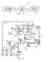
- a hemodialysis monitoring system is designated generally by the reference numeral 10.
- the monitor 10 includes an input module 12, which can preferably be a urea sensor or an appropriate sensor for sensing a different molecule or constituent to be cleared.
- the module 12 samples a volume of the dialysate effluent intermittently, as desired.
- the module 12 couples the dialysate sample volume to a sensor 14 via a line 16.
- the sensor 14 generates a signal which is proportional to the monitored constituent concentration and couples that signal to a constituent signal analyzer 18 via a line 20.
- the module 12 can be any type of sampling device which is coupled, preferably permanently, to the dialysate effluent line (not illustrated).
- a preferred input module 12 is disclosed and described in US-A-5,442,969 (which is a continuation application derived from (docket number Serial No. 07/960,088, filed October 12, 1992 , entitled “FLUID SAMPLING MODULE,” filed concurrently herewith).
- the urea sensor 14 can be a sensor, such as described in U.S. Patent No.
- a urea sensor that includes a urease layer associated with an electrode adapted to generate output in response to ammonium ions.
- the urease layer converts a portion of the urea in the sample to ammonium ions, and the ions contact the electrode to generate output related to the urea concentration in the sample.
- the sensor 14 is described herein, for example purposes, as a urea sensor.
- Urea is just one of a number of identifiable constituents generally related to uremia in a patient's blood, which can be utilized as a marker or measure of the effectiveness of the hemodialysis treatment, i.e., the removal of toxins.
- Such other constituents are, for example, creatinine, uric acid, phosphate, calcium, sodium, potassium, glucose, beta 2 micro globulin, among others.
- Other types of sensors also can be utilized in the hemodialysis monitoring system of the present invention, which sense the required fluid constituent(s) direct or indirectly.
- the most direct configuration is location of the urea sensor in the effluent dialysate stream.
- Another direct configuration is taking the sample volume from the fluid stream and flowing the sample volume past the sensor.
- Other configurations could include:
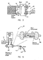
- the module 30 includes a sample port 32, which preferably forms a part of a discharge or dialysate effluent line 34.
- the module 30 taps into the dialysate effluent line 34 via a junction 36 coupled to a sampling line 38.
- the module 30 samples the dialysate effluent by activating a self-occluding peristaltic or roller pump 40.
- the line 38 is coupled to a junction 42 and to a normally closed valve 44.
- the junction 42 also is coupled to a line 46, which includes a storage coil 48.
- the storage coil 48 is first filled with the dialysate effluent, with the excess dialysate effluent continuing through the line 46 to a separator 50.
- the separator 50 includes an air gap, which prevents a backup of dialysate effluent and also prevents an electrical short through the line 52.
- the pump 40 is stopped, which closes the line 38 from the junction 36.
- the valve 44 then is opened, allowing the sample dialysate to flow through the valve into a line 54, and then to and past the urea sensor 14.
- the sample dialysate is caused to flow by a sample pump 56, which is coupled between the urea sensor 14 and the discharge separator 50 by a line 58.
- sample dialysate preferably is input to the urea sensor 14 and flushed through the separator 50 several times to ensure a good sample value.
- the sample dialysate is pumped through the urea sensor 14, a reference fluid from a source 60 also is pumped into the urea sensor 14 via a line 62 and a second pump 64.
- the second pump 64 preferably can be a second roller head on the sample pump 56, but could also be a second pump coupled to operate at the same time as the sample pump 56.
- the urea sensor 14 includes an air detector 66 to determine if the sample dialysate is present in the urea sensor 14.
- the sensor 14 employs an electrode 68 with a membrane (not illustrated) which is specific to ammonium.
- the electrode 68 senses dialysate urea nitrogen (DUN) which is compared to a reference electrode 70.
- DUN dialysate urea nitrogen
- both a low reference standard and a high reference standard are run on the module 30 to calibrate the module 30.
- the valve 44 remains closed and a valve 72 is opened to allow the second pump 64 to draw in the low standard fluid from a source 74 via a line 76.
- the urea sensor 14 measure the low standard, which is compared to an expected range of values to ensure that the urea sensor 14 is calibrated correctly.
- the low standard also can be utilized to test the integrity of the system during treatment.
- a similar operation is performed with a high reference standard.
- all the valves are closed, except for a high standard valve 78.
- the open valve 78 allows the second pump 64 to draw a high standard fluid from a source 80 via a line 82.
- the high standard fluid is measured in the urea sensor 14 and compared to an expected range of values to ensure that the urea sensor also is operating correctly at a high standard range.
- the module 30 closes the valves 44, 72, and 78, and opens an air valve 84 for a period of time, which allows the sample pump 64 to draw air into a line 86 through the valve 84, the urea sensor 14, and out the discharge line 52.
- This air segment between each fluid segment helps ensure that the urea sensor 14 and the lines 54 and 58 are clean and empty of any substantial amount of residual fluid.
- a schematic embodiment of the operation of the hemodialysis monitoring system 10 is designated generally by the reference character 90.
- the system 90 is depicted diagrammatically as including an intracellular space (ICW) 92 and an extracellular space (ECW) 94, which spaces are representative of the body pools in a hemodialysis patient.
- the hemodialysis kinetic parameters in the system 90 are calculated from the spent dialysate of a patient undergoing a typical dialysis treatment.
- the urea is generated in the liver, which is illustrated as being a portion of the ECW 94.
- urea may be removed by the patient's kidneys, if there is a residual renal function, as indicated by an arrow 96. the majority of the urea, however, is removed by the hemodialysis treatment after first contacting the blood 98 in the ECW 94, as indicated by an arrow 100. Urea also enters the ECW 94 from the ICW 92, as indicated by an arrow 102.
- the blood is removed during the hemodialysis treatment by flowing through a line 104 into a dialyzer 106.
- the dialyzer 106 diagrammatically includes a dialyzer membrane 108 across which urea diffuses into the dialysate.
- a sample volume of the dialysis effluent is removed through the line 38 and then is sensed by the urea sensor 14, as above described.
- the blood return to the patient via a line 110.
- the total amount of urea removed during the hemodialysis treatment and sensed by the urea sensor 14 is equal to the rate of generation of urea in the patient's body in ECW 94.
- This allows the calculation of the normalized protein catabolic rate (nPCR) or the number of grams of urea generated per kilogram of body mass in a twenty-four hour period.
- nPCR normalized protein catabolic rate
- KT/V clearance-time/body water index
- FIG. 4 illustrates a urea concentration time profile of a typical patient as detected by the urea sensor 14.
- Applicants have discovered that the urea-concentration time profile can be closely matched to an early fit exponential curve 112 and to a late fit exponential curve 114.
- the two curves 112 and 114 are exponential fits of the urea concentration data pre and post thirty (30) minutes into the hemodialysis treatment.
- An empirically determined "inflection" point 116 is indicative of the differences in the fits 112 and 114, which is gradual shift caused by the two-pool nature of the urea removal from the patient's ICW 92 and ECW 94.
- the system 90 removes urea quite rapidly from the patient's blood and from the ECW 94 with which the blood 98 is in intimate contact.
- the initial fit 112, before the point 116 is a fairly steep slope.
- enough urea is removed from the ECW 94 to create a urea gradient between the ICW 92 and the ECW 94.
- the rate of urea removal from the ECW 94 decreases and the rate of urea removal from the cells in the ICW 92 increases.
- the latter is a result of a growing concentration differential between the ECW 94 and the ICW 92.
- the removal of urea from the patient's body is dependent upon the intercompartmental mass transfer area coefficient (iMTAC) (which controls mass transfer between the ICW 92 and ECW 94) and the dialyzer mass transfer area coefficient (dMTAC) (which controls the mass transfer between the ECW 94 and the dialysate flow).
- iMTAC intercompartmental mass transfer area coefficient
- dMTAC dialyzer mass transfer area coefficient
- the calculation of KT/V, URR, and SRI, employing the two-pool analysis in accordance with either of the systems 10 or 30, is as follows.
- the hemodialysis monitoring system 10 or 30 prior to initiating the hemodialysis treatment, is equilibrated with the patient's blood, as illustrated in FIG. 5 .
- the blood is pumped to the dialyzer 106 via the line 104, such as by a roller pump 118.
- the dialyzer 106 is connected to and forms a portion of a conventional dialysis machine 120.
- the dialysate flow is shunted past the dialyzer 106 or stopped, while the blood is pumped through the dialyzer 106. No dialysate flow is allowed between the dialyzer 106 and the dialysis machine 120, however, ultrafiltration does exist even with the dialysate flow in bypass.
- an elapsed time period such as five (5) minutes, during which the urea concentrations of the blood and the dialysate are allowed to equilibrate across the membrane, an equilibration sample is obtained and sensed by the urea sensor 14.
- the equilibration sample provides the urea concentration in the patient's blood before the dialysis treatment.
- the equilibrated concentration is utilized in conjunction with the dialyzer typical profiles, dialysate clearance (K), and total body water (V), to calculate KT/V, URR, nPCR, and the solute removal index (SRI).
- the first embodiment can be utilized when it is not possible or desirable to obtain an equilibration sample.
- the second embodiment can be utilized when it is possible to obtain an equilibration sample, especially when the system 10 is integrated with or is able to automatically control the hemodialysis machine.
- numbers 1 and 3 result in a KT/V that represents single pool urea kinetics
- the preferred embodiments, previously described and the further embodiment number 2 result in a KT/V that represents two pool urea kinetics.
- the hemodialysis monitoring system 10 can draw a sample volume at any predetermined time period. It empirically has been determined that a time period on the order of every ten (10) minutes is sufficient for the hemodialysis treatment, since the urea concentration values change at a relatively slow rate. The rate change is sufficiently slow, such that continuous sampling is not required and intermittent sampling is sufficiently accurate to represent real time. Thus, sampling the dialysis effluent every five (5) to ten (10) minute periods provides a real time urea concentration profile.
- a convenient sample volume, utilizing the urea sensor 14 is on the order of two (2) milliliters (ml) of dialysate effluent.
- the hemodialysis monitoring system 10 can also provide an equilibrated urea concentration value at the end of the hemodialysis treatment.
- the final urea concentration value can be projected. This mid-treatment projection then can be utilized to troubleshoot the hemodialysis treatment, if the final projected KT/V result is too low.
- the patient's blood will contain on the order of seventy (70) milligrams (mg) of urea in one hundred (100) ml of blood. After four (4) hours of the hemodialysis treatment, the patient's blood will contain on the order of thirty (30) mg of urea in one hundred (100) ml of blood.
- the dialysate On the dialysate side of the dialysate cartridge 106, the dialysate, after initiating treatment initially will contain on the order of twenty-five (25) mg of urea in one hundred (100) ml of dialysate.
- the dialysate will contain on the order of five (5) to seven (7) mg of urea in one hundred (100) ml of dialysate, since blood concentration decreases during the hemodialysis treatment.
- the urea change is exponential, such that about one-half of the urea is removed in about one-third of the total hemodialysis treatment time period. Since the urea change is exponential, it is convenient to sample more frequently in the initial part of the hemodialysis treatment time period. For example, during a four (4) hour hemodialysis treatment, the hemodialysis monitoring system 10 can be set to sample every five (5) minutes in the first hour and then every ten (10) minutes during the rest of the hemodialysis treatment.
- the two-pool analysis of the hemodialysis monitoring system 10 is on the order of twelve (12) to eighteen (18) percent more accurate then the conventional one-pool analysis.
- the hemodialysis monitoring system 10 also is set to monitor the dialysis effluent, only when the hemodialysis machine 120 is operating. Some prior art systems utilize a total clock period, without regard to dialysis shut down periods due to system alarms.
- the hemodialysis monitoring system 10 is prevented from sampling the dialysate effluent during a period of no or very low dialysate effluent flow. Sampling during a period of no or unstable flow, also can introduce errors into the analysis treatment.
- Urea is a convenient marker to utilize in the hemodialysis treatment, since it is related to other uremic toxin levels, but other well-known markers also can be utilized in the hemodialysis treatment as previously described.
- the prior art hemodialysis monitoring treatment typically draws a blood sample from the patient (an invasive treatment), typically on the order of once a month.
- the urea concentration value then is utilized as the initial hemodialysis treatment value.
- the final or post hemodialysis treatment value is obtained from a blood sample taken after the end of the hemodialysis treatment.
- the urea concentration ratio from these two blood samples then is utilized to determine the efficiency of the hemodialysis treatment, which provides a KT/V value which is not as accurate as that obtained utilizing the present invention.
- urea concentration in the ICW 92 attempts to equalize with that in the ECW 94, there is considerable time lag.
- the urea is removed rapidly from the blood, resulting in a significant differential between the urea concentration in the ICW 92 and in the ECW 94 at the end of the hemodialysis treatment.
- urea concentrations can be about forty (40) mg/dl in the ICW 92, and about thirty (30) mg/dl in the ECW 94.
- the ICW 92 has a total nominal volume greater than the ECW 94 total nominal volume, the final ECW 94 urea concentration value of about thirty (30) mg/dl can be very inaccurate.
- the single or one pool analysis does not take into account the difference between the final urea concentration in the ICW 92 and the ECW 94. Since the one pool analysis generally is based upon the urea concentration in the ECW 94, if an equalization or rebound period on the order of thirty (30) to sixty (60) minutes is not accounted for, the analysis will overestimate the true KT/V. Continued diffusion from the ICW 92 into the ECW 94 causes the concentration of the ECW 94 to rebound or increase with time.
- the hemodialysis monitoring system 10 is described as a separate unit, which is attached to the lines of the dialyzer 106, which is part of the dialysis machine 120.
- the hemodialysis monitoring system 10 also can be retrofit to the dialysis machine 120, or can be fully integrated into the dialysis machine 120.
- FIGS. 7 and 8 it becomes possible to obtain a plurality of pre-, post-, and mid-dialysis equilibrium samples on any dialysis machine.
- the device of FIGS. 7 and 8 can be, for example, attached to a dialysis machine such as that commercially marketed under the trade name Baxter BioStatTM 1000, the sampling portion of which is described with reference to FIGS. 1-6 , previously discussed herein.
- the intercompartmental transfer coefficient (K I ) for the two pool kinetics for a patient undergoing dialysis can be obtained to permit a much more precise adjustment of the prescriptive treatment for the patient undergoing dialysis.
- the equilibration volume is on the order of the size of the dialyzer dialysate compartment with a small amount of added tubing, i.e., approximately 150 milliliters, in the case of machines such as the German DT or the Hospal machine, larger or very large dialysate loops on the order of greater than 150 milliliters are encountered so that equilibration takes much longer than five (5) minutes, an amount of time which may be unacceptable in an ongoing dialysis treatment.
- post-run equilibration samples require additional manual intervention, and as a result may be either intentionally or inadvertently omitted even though they provide additional useful information for purposes of modifying and/or validating the prescribed treatment.
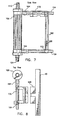
- bypass loop apparatus 160 as shown in side view in FIG. 7 and top view in FIG. 8 .
- the system is the same as that shown and described with reference to FIGS. 1-6 .
- the modification illustrated can be done, for example, on a urea monitor, such as the Baxter BioStat 1000TM urea monitor, to include a semiautomatic bypass system to allow automation of the equilibration sample.
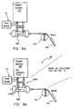
- the device is made up of a valve and flow detector which is connected, for example, to a Baxter BioStat 1000TM urea monitor as illustrated in FIGS. 9A and 9B .
- the device of the invention is described with specific reference to the Baxter BioStat 1000TM urea monitor, it will be readily apparent to those of ordinary skill in the art that it can also be used with other urea monitors to automate the operation thereof.
- a valve In use, when an operator energizes the device from its keypad, a valve opens and bypasses the dialyzer by directing dialysate flow back to the machine as is more clearly seen with reference to FIGS. 9A and 9B , described in greater detail hereafter in the text.
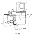
- the bypass loop apparatus 160 is connected to a dialysis cartridge 106 through standard couplings 164 such as Hanson connectors.
- a solenoid valve serves as a bypass valve 162 to divert dialysate flow through a flow meter 166, so as to allow the dialysate in the dialyzer 106 to equilibrate with the blood plasma water which is pumped through the blood side of the dialyzer 106.
- Dialysate in the dialyzer 106 remains at the set membrane pressure through the connecting arm 170 which allows the aforementioned ultrafiltrate to be sampled by the hemodialysis monitoring system 10. As further shown in FIG.
- the bypass loop apparatus 106 can be mounted on a saddle member 168, which is mounted on the dialysis monitoring system 10, which allows the entire unit to be assembled in a compact manner.
- Flow meter 166 allows reading of volumes of dialysate being passed through the dialysis machine to enable calculation of the various values necessary to the proper operation of the system in accordance with the invention.
- the bypass loop apparatus 160 which is attached to the dialysis machine and dialyzer 106 permits bypassing of the dialyzer 106 under conventional software control and appropriate conventional mechanical/electrical connections to permit blood to equilibrate with a smaller than normal dialysate pool in the dialyzer 106. This permits a dialysate sample to be taken which has the same plasma water concentration of a metabolite as the blood, i.e., what is conventionally known as an "equilibrium" or "equilibration" sample.
- the equilibration sample can be used in various ways. Initially, it is desired to use a pre-run equilibration sample to separate the values for K and V as previously described herein with reference to FIGS. 1-6 .
- the rate at which the blood urea nitrogen (BUN) concentration rises in the blood, from corresponding post-run equilibration samples after dialysis treatment is directly related to the intracellular to extracellular transfer rate of metabolite within the body of the patient. This rate has previously been described herein as the two-pool intercompartmental transfer coefficient which is used to predict the effect of intervention or changes in a dialysis treatment to improve dialysis efficiency.
- a mid-run equilibration sample can be used to check dialyzer clearance to ensure that slow changes in clearance due to, for example, clotting, are not occurring.
- dialysate flow rate e.g. 200 ml/minutes
- the user collect out flow dialysate for a given period of time and/or rely upon the initial flow calibration of the machine.
- these types of machines frequently have different flow rates and/or collecting dialysis out flow is inconvenient, erroneous data is often obtained.
- the flow meter 166 it become possible to immediately determine what the dialysis flow rate is at any time that equilibration is being conducted.
- the dialysis flow bypass can be created by placing solenoid value 162 in the bypass position.
- This bypassed dialysate flows away from the dialyzer 106 allowing the dialysate compartment of the dialyzer 106 to equilibrate with blood passing therethrough. No manual intervention is required therefore to run equilibration samples, before, during, or after a dialysis run.
- the multiple equilibration samples obtained can be used to calculate the intercompartmental transfer coefficient of a particular patient, i.e., (K I ), as well as do a separate mid-run check of the dialyzer 106 clearance (K).
- dialysate flow can be read directly from the apparatus 160 by viewing the flow meter 166, as opposed to relying upon timed collections or manual entry.
- the apparatus of Figures 1-6 can be used in conjunction with the apparatus of Figures 7 and 8 to measure the metabolite in the equilibrated dialysate.
- K I intercompartmental transfer coefficient
- a physician or dialysis nurse/technician must measure KT/V, change the prescription, measure KT/V again, and make another prescription change, and so on, until an optimum therapy for the patient is obtained.
- the two-pool parameters explicitly, i.e., the intercompartmental transfer coefficient K l of a patient, this allows the number of interactions necessary to obtain an optimum prescription to be decreased.
- a consequent advantage is that a more efficient use of staff time and lab facilities is obtained.
- bypass solenoid valve 162 In operation, when it is desired to equilibrate dialysate in the dialyzer 106, the bypass solenoid valve 162 is actuated. This shuts the flow off from the bottom of the dialyzer 106 and reroutes it through the flowmeter 166 in the central column where it is subsequently returned to the dialysis machine. The flow through the central column of the flowmeter 166 maintains the system at a transmembrane pressure set by the dialysis machine. This causes the ultrafiltration which facilitates the equilibration of the dialysate with the blood flowing through the dialyzer 106.
- the bypass apparatus 160 can be constructed in a telescoping arrangement to account for different size dialysis cartridges 106.
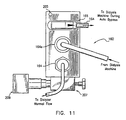
- FIGS. 10 and 11 illustrates an alternative embodiment of the device of the invention.
- a bypass valve/unit 160 is connected to the dialysate inflow line, at a Hansen-type connection 164a. From there, depending upon the position of bypass valve apparatus 160, dialysate flows to dialyzer 106 to which the bypass valve apparatus is connected at connector 164, or bypasses the dialyzer 106 to be caused to flow through a flow meter 166 connected at connection 164 to the dialysis machine during automatic bypass.
- a status light 205 indicates apparatus 160 position.
- the bypass valve apparatus 160 is mounted to the dialysis machine 120, for example, through a mounting block 207 onto a rod thereof, and the dialyzer clamp 209 serves to hold the dialyzer 106. In bypass mode, flow from the bypass valve apparatus 160 connects at a T connection 201 to return dialysis flow to the dialysis machine 120 at a mounting pole.
- the bypass system is made up of two major components.
- a first component is the bypass apparatus 160, and a second part is the bypass tube set, for example, as the tubes shown with replaceable tubes connected to the various units through Hansen connectors 164 and 164a.
- the bypass apparatus 160 includes a valve, the flow detector 166 (replaceable), and a saddle therefor, and the status light 205.
- An equilibration sample can be obtained by placing the dialysis machine into bypass mode by activating valve 162 to produce a dialysate bypass with the blood pump running. Ultrafiltration and diffusion take place from the blood compartment of the dialyzer 106 to the dialysate compartment so that after a set equilibration time (t equil ), the dialysate concentration in the dialyzer 106 would be the same as the plasma water concentration of the blood. Since t equil is not necessarily known, however, dialysate samples are taken sequentially until the measured concentrations only differ by a small amount (C Delta ). The higher of the last two samples is then assumed to be the equilibration sample. This procedure can be followed prior to, during, or after the completion of dialysis. When performed during or after dialysis C Delta is less than C Delta prior to the start of dialysis due to the fall in BUN.
- one equilibration sample will be taken at the beginning of dialysis in order to separate clearance (K) from the volume of urea distribution (V).
- Three or more additional equilibration samples (C t ) taken serially at specified intervals after the completion of dialysis, or after the blood pump is shut off midway through dialysis, will allow the intercompartmental transfer coefficient (K I ) to be obtained.
- the sampling interval would be every five (5) minutes, although shorter time intervals (e.g., two (2) minutes) could be used to reduce the total time the patient is in the unit.
- C t is the post-dialysis equilibration concentration at time t, where zero time is the end time of dialysis, C 0 is the concentration immediately post-dialysis (which is an immeasurable value since a given concentration value requires a finite equilibration time and there will have been no equilibration time immediately post dialysis), C ⁇ is the concentration at infinite time and ⁇ is a time constant.
- ⁇ , C 0 , and C ⁇ can be obtained from the fitting procedure. The urea generation rate and residual renal function are not included in this formula.
- V e and i V are the intra- and extra-cellular volumes respectively, and V T is obtained using the pre-dialysis equilibration sample and the algorithm previously described with reference to FIGS. 1-6 .
- K I can also be obtained by obtaining equilibration samples as before, by initially placing the dialysis machine into bypass with the blood pump running so that ultrafiltration and diffusion can take place to equilibrate dialysate in the dialyzer 106 and then sampling until successive measured concentrations differ by only a small amount. At least one, but preferably two or more equilibration samples (C t ), can then be taken during but preferably after the end of dialysis.
- this method differs in that unlike the previously described situation which determined K I based purely on data obtained during a period when dialysis has ceased, e.g., when the blood pump is shut off, the intra-dialytic concentration information is also used to calculate K I . This will tend to give more reliable estimates of K I and is to be preferred over the earlier method. Moreover, unlike the previously described situation where the ratio of V e to V I is assumed to have a specific value, nonlinear-fitting techniques can also be used to compare the dialysis and post-dialysis concentrations of metabolite to the measured concentrations to obtain the best value for K I and V e /V i , assuming current values for G, K, K R , and V T . These values are obtained using the pre-dialysis equilibration sample and the algorithm previously described with reference to FIGS. 1-6 .
- SSQ is the sum of the square of the differences between C e and the equivalent measured blood concentrations (C Beq ) during dialysis and the equilibration concentrations (C eq ) after dialysis.
- C Beq is obtained from the measured dialysate concentrations.
- SSQ may be minimized through a variety of numerical techniques and the best fitting values of K I and R V are each varied through their appropriate ranges (200-1,600 ml/minutes for K I ) and (0.5 to 0.9 for R V ) in specific increments, and SSQ is computed for each pair of values. The best value for K I and R V is then the pair of values which result in the minimum SSQ.
- the limitation of this technique is that many calculations are required if the increment is small. For example, if K l is varied in 50 ml/minute increments and R V is varied in 0.05 increments, then 28 ⁇ 8 or 224, computations of SSQ have to be performed.
- K I and R V are more precise than the given increments.
- a more elaborate method needs to be employed, as will be readily apparent and known to those of ordinary skill in the art.
- Such methods can include conjugate gradient methods, quasi-Newton methods, downhill simplex methods, and direction-set methods. All such methods allow the parameters to be predicted, i.e., K I and R V , to be varied in a predictable fashion so that precise values may be determined.
- the invention describes an apparatus which allows an equilibration sample to be automatically obtained on any type of hemodialysis machine thereby eliminating operator error and verifying the constancy of "K" (and thus the lack of gradual dialyzer clotting).
- K I the intercompartmental transfer coefficient
- R V the ratio of the extra- to intra-cellular volumes.
- knowing R V also implies explicit knowledge of the actual intra- and extra- cellular volumes.
- K I is not strictly necessary to perform dialysis or assess dialysis adequacy, however, it provides valuable information as to how a given intervention will affect outcome. For example, a higher KT/V can be obtained by either increasing K or T. Increasing time (which implies increased staff time and poorer utilization of dialysis facilities), however, is usually done secondary to increasing clearance (K) which can be raised, for example, by increasing blood flow, dialysate flow or dialyzer size. Patients with an extremely low intercompartmental transfer coefficient (K I ) will not, however, respond adequately to purely an increase in clearance.
- Knowing K I will enable a user to ascertain a priori the effect of a given intervention on the dialysis prescription, measure the KT/V again, make another prescription change, etc., in order to obtain an optimum therapy for the patient. Knowing the two-pool parameters (i.e., intercompartmental transfer coefficient) for a given patient will decrease the number of iterations necessary to obtain an optimum dialysis prescription. This will make more efficient use of staff time and laboratory facilities.
- R V gives some indication of the state of patient hydration. Generally, dialysis patients have expanded extracellular volumes which consequently results in a higher value of R V . If, however, R V is low, the probability of intra dialytic hypotension increases. Knowing R V can help to avoid this. Even more important is the value of the intra-cellular volume which can be obtained from R V . The latter parameter is an indication of body cell mass. When dialysis patients are maintained on hemodialysis for an extended period of time, there is often "wasting" or a shrinkage of the muscle mass. By tracking intra-cellular volume over time, nutritional interventions can be made before malnutrition becomes a significant problem.
- a clock in the system counts up and the urea monitor takes its first sample at two (2) minutes and continues to sample every two (2) minutes until the change in concentration between two (2) consecutive samples is two (2) mg/dl or less when the procedure is performed prior to the start of dialysis, or less than a proportionately smaller difference when the procedure is performed later in the dialysis treatment when the level of BUN has fallen.
- the urea monitor uses the higher of the last two samples as its equilibration sample result, prints the equilibration result and automatically turns off the bypass apparatus 160 valve and starts the treatment clock.
- the urea monitor If the concentration difference between two (2) samples does not fall below the specified minimum concentration difference by the end of the twelve (12) minute sample (12 minutes is the maximum time for equilibration with the bypass apparatus 160 valve), the urea monitor then prints "Equil. unsuccessful,” and automatically turns off the bypass apparatus 160 valve, and starts the treatment clock. Sensors and safety devices of a conventional nature are incorporated to alert a user of a bypass apparatus 160 valve failure.
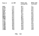
- hemodialysis patients were enrolled in a feasibility study. Patients were studied during the first fifteen (15) minutes of a single dialysis session. A two (2) ml blood sample was taken from the patients' access device after needles were in place. The patients were then put on dialysis in a normal manner. Prior to the start of the run, a bypass apparatus 160 valve was connected to the inflow and outflow dialysate lines of the dialysis machine 120. The apparatus 160 valve bypassed dialysate from the dialyzer 120 from reaching the cartridge 106. Upon initiation of dialysis, the urea monitor commenced sampling the equilibrated dialysate. As soon as the measured urea concentration became constant, the concentration was recorded, and the bypass apparatus 160 valve shut off or removed to allow the dialysis session to continue as normal.
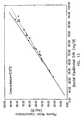
- FIG. 12 shows in table form the predialysis urea concentration as measured by the modified urea sensor of the invention, with the bypass valve system, compared to BUN measured in a clinical laboratory by use of the commercially available analyzer known under the trade name "Beckman CX3 analyzer," and the plasma water corrected labortory results (measured BUN divided by 0.93).
Abstract
Description
- The present invention relates generally to hemodialysis machines and methods for on-line, real time monitoring of the effectiveness of the hemodialysis treatment, and more particularly, for obtaining the intercompartmental transfer coefficient for two pool kinetics in hemodialysis.
- The use of dialyzers with hemodialysis machines to remove blood-borne toxins and by-products of metabolism has been conventional for many years. Typically, such a dialyzer contains a pair of chambers separated by a semipermeable membrane. Blood is perfused through the first chamber returned to the patient. The dialysate solution is simultaneously circulated in the opposite direction through the second chamber. A concentration gradient thereby is established which causes waste products carried in the blood to diffuse through the semipermeable membrane and into the dialysate solution to form the dialysate effluent.
- The principle of hemodialysis has been refined extensively. A number of semipermeable, hollow fiber membranes are now utilized in dialyzers to greatly increase the total membrane surface area to facilitate diffusion across the membrane structure. The hollow fiber membranes include a variety of materials including, for example, cellulose acetate, cellulose triacetate, polyacrylonitrile, polysulfone, and regenerated cellulose.
- One of the most basic considerations in treating a patient with hemodialysis revolves around treatment adequacy, for instance, the length of time a given patient should be dialyzed on a given day. A number of medically adverse effects may result from an inadvertent failure to sufficiently dialyze the patient. At the present time, the average dialysis patient has a life expectancy of only about five years. One reason these patients tend to have a short life expectancy is the deleterious effect of a chronic buildup of various toxins that either are not eliminated at all, i.e., do not pass through the hollow fibers, or are not sufficiently reduced to nontoxic levels. The identity of many of these supposed toxins is not known, although those species known to be eliminated in urine, such as urea, creatinine, phosphate, hydrogen ions, etc., are associated with serious medical consequences when permitted to accumulate in excess of normal levels.
- A number of factors can have a substantial effect on treatment adequacy. For example, it is common practice in the field of hemodialysis to reuse the dialyzers. There is technology available for cleaning, disinfecting, or sterilizing used dialyzers, for example, as illustrated in
U.S. Patent No. 4,695,385 . Eventually, however, an individual dialyzer must be discarded because it loses its dialyzing competency. At the present time, the competency of dialyzers is difficult to assess and, therefore, often is not rigorously monitored, and a dialyzer cartridge is often not discarded until it visually appears unclean after reprocessing, or when fiber bundle volumes or ultrafiltration rates are reduced below a predetermined threshold. It now is known that severe dialyzer dysfunction can occur even when appearance, fiber bundle volume, and ultra filtration rates are normal, as reported by Delmez et al., "Severe dialyzer dysfunction during reuse," Kidney International, 35:244 (1989). It is also known that dialyzer competency can not be accurately predicted by the age of the dialyzer cartridge or the number of uses. - Notwithstanding the condition of the dialyzer, one measure of adequacy of dialysis for the individual patient during a given treatment is calculated from the following equation:

- It has been determined empirically that KT/V values of about 0.8 or greater are associated with low levels of morbidity. See Gotch, L.A., Sargent, J.A. Kidney International, 28:526-537 (1985). Even with the use of new dialyzers there is some risk that a unit selected from a particular lot will have a significantly lower K value than the value indicated in the product insert. The patient receiving treatment from such a dialyzer is therefore at risk of being under-dialyzed. The likelihood of under-dialysis increases upon reuse of the dialyzer because of the definite but unquantified loss of dialyzer competence with each successive use. Under-dialysis also may occur because of incompetency of access to the patient's circulation. Because of incompetency of the patient's blood access, desired blood flow rates may not be achieved which also can result in under-dialysis.
- Other parameters than KT/V have also been determined to assess the adequacy of dialysis. Among these are the Urea Reduction Ratio (URR) and Solute Removal Index (SRI). URR is defined as 1-(CB)pre/(CB)post. An ideal dialysis treatment will have a URR greater than 0.75, while a poor dialysis treatment will have a URR less than 0.50. Unfortunately, URR does not take into account generation of urea during dialysis, ultrafiltration, or the two-pool nature of removal. Consequently, SRI has been proposed as a generalized version of URR, which does account for these effects. SRI is defined as the amount of urea removed during a treatment as a fraction of the total body store. Like URR, a good dialysis treatment will have an SRI value greater than 0.75, while a poor dialysis treatment will have an SRI less than 0.50. Potentially, SRI, (unlike KT/V), can indicate the adequacy of a dialysis treatment, irrespective of modality (i.e., peritoneal or hemodialysis), and intermittence. Neither URR or SRI, however, have been validated as extensively as KT/V as measures of dialysis adequacy.
- Although the KT/V, URR, and SRI indices are indicative of urea removal and appear to correlate to therapy failure, that is not tantamount to saying that urea is a toxic metabolite. There is early literature to suggest that urea is not toxic, per se. However, urea is a major metabolite of protein catabolism and serves as a convenient marker to monitor treatment adequacy.
- Urea has a molecular weight of 60 Daltons, while some of the other protein catabolites may be much larger. It has, therefore, become a subject of controversy whether the relationship between KT/V and morbidity, established with the tighter cellulosic membranes, is applicable to the more open membranes used for hemofiltration and high flux hemodialysis or to the natural peritoneal membrane.
- There is a considerable body of literature on the urea kinetic model. Computer programs, programmable calculators, and time-shared computer services, have been developed to make urea kinetics more accessible to the dialysis clinician. It has recently been shown (Lindsay et al., 1989) that KT/V values of less than 0.8 may be associated with a low dietary protein intake that is intractable to nutritional counseling. However, increasing the KT/V to 1.0 or higher, in conjunction with nutritional counseling, is effective in improving dietary protein intake. As low dietary protein intake may be associated with increased morbidity, monitoring of the KT/V, and nPCR are useful adjuncts to other clinical assessments of the dialysis patient.
- Traditional urea kinetics entails numerous measurements and is considered mathematically complex by dialysis clinicians. The various measurements required for accurate kinetic measurements are summarized in Table 1.
TABLE 1 MEASUREMENTS REQUIRED FOR UREA KINETIC CALCULATIONS Pre dialysis BUN (C1) Post dialysis BUN (C2) Pre-dialysis BUN for next dialysis (C3) Dialyzer clearance (K) Blood flow rate Arterial BUN Venous BUN dialysate flow rate (effluent) (Qdo) Access recirculation Peripheral BUN Residual renal function Urine volume Urine concentration Dialysis duration (td) Off dialysis duration (tod) Ultrafiltration rate Weight gain between dialyses - Prior art hemodialysis machines have not had the capability of on-line monitoring of the hemodialysis treatment. Further, the prior art techniques generally have required the taking of blood samples from the hemodialysis patient.
- In considering the invention it is noted that, for example, the Baxter BioStat 1000™ urea monitor, on which the invention may be employed, is a noninvasive device which connects to the dialysate outflow of the dialyzer and measures the concentration of urea in discrete samples of dialysate. From these concentrations, the amount of urea removed from a patient and various kinetic parameters, such as KT/V (clearance time divided by volume of distribution), can be, and are, calculated. In order to separate clearance (K) from volume (V), an equilibration sample is taken prior to the start of dialysis. This involves placing the dialysis machine into dialysis bypass and starting blood flow and ultrafiltration for up to 10 minutes while the concentration of urea in the blood equilibrates with the concentration of urea in the dialysate. Because the process is under operator control, the amount of time and/or ultrafiltration can be either too little or too much. While this procedure is possible for most dialysis machines, there are some machines that do not allow an equilibration sample to be obtained.
- The device according to the invention provides an automated bypass and equilibration function which automates the current manual process of obtaining a predialysis equilibration sample. The device also allows the equilibration sample to be obtained with machines that are incompatible with the manual procedure.
- In accordance with the invention, a desirable and reliable noninvasive, on-line real time monitoring of the hemodialysis treatment would be provided, both before and while the patient is attached to the hemodialysis machine. The treatment, when based upon urea kinetics, preferably would require measurements of effluent dialysate concentrations and flow but not of blood samples. The treatment would yield as outputs the KT/V, URR, and SRI indices of therapy adequacy, the urea removal and the normalized protein catabolic rate (nPCR), which then could be utilized to assess dietary compliance and adequacy of treatment in real time. Equilibration is achieved automatically and reliably prior to commencing dialysis to result in a highly reliable treatment regimen.
- The invention of
US-A-5,518,623 (U.S. application Serial No.08/239,936, filed May 9,1994 ) and ofWO-A-94 108641 - The present invention adds to the invention of
US-A-5,518,623 (application Serial No.08/239,936 ) by providing a device for obtaining the intercompartmental transfer coefficient (KI) for a patient undergoing hemodialysis treatment. - According to the present invention, there is provided an apparatus for conducting equilibration of dialyoate with a patient's blood for a patient undergoing hemodialysis according to claim 1.
- When the dialysate flow bypasses the dialyzer with the blood pump running diffusion continues to occur, and an ultrafiltrate from the blood passes into the dialysate compartment of the dialyzer. Eventually, due to this diffusion and convection, the dialysate in the dialyzer reaches a metabolite concentration equal to the patient's plasma water concentration. At this time the dialysate may be sampled and measured. This process may occur prior to, during, and/or after the hemodialysis treatment. When such a concentration is obtained before dialysis, "K" and "V" may be separated. When at least one concentration is obtained after dialysis the intercompartmental transfer coefficient KI may be reliably determined.
- In a method of obtaining an equilibrated dialysate sample whose metabolite concentration is the same as that of the plasma water of the blood of a patient, a dialysate flow to a dialyzer is stopped while the blood pump is allowed to run and ultrafiltration to take place from the blood of a patient. The concentration of a selected metabolite, typically urea, is measured initially, after partial equilibration, to obtain a first sample from which the concentration is measured. The metabolite concentration is measured in an obtained second sample after a specified time has passed. The two measured concentrations are compared, and sampling/measuring is continued until the difference between two successive samples is less than a specified amount.
- In a method for automatically obtaining the intercompartmental transfer coefficient for a patient undergoing hemodialysis with a dialysis machine, the method of obtaining an equilibrated dialysate sample, as discussed above, is first conducted. Thereafter, the blood pump continues to run with the dialysis machine in bypass mode, and samples which have been equilibrated are taken at regular time intervals. The rate of change of metabolite concentration, typically urea, after the end of a hemodialysis treatment is determined from the measurements. The ratio of the extra- and intra-cellular volume (RV) of a patient is determined from the rate of change of metabolite concentration in the patient's blood.
- Preferably blood concentration (Cbew) of metabolite is measured at intervals during dialysis. By using non-linear fitting techniques, KI and/or the intra- and extra-cellular volumes of a patient can be obtained from the obtained equilibration samples and the blood concentration (Cbew) measurements. Yet more preferably, a pre-run equilibration sample can be obtained to separate K and V once the ratio of K/V is known. A mid-run equilibration can be obtained to estimate K. While the method has been described in the context of periodic sampling, it can also be employed in hemodialysis machines which conduct continuous sampling. Samples at discrete time periods can be used to practice the methods
- The invention relates to a device suitable for conducting the above-described method. The device includes a bypass device connectable between the inlet and outlet of the dialyzer and dialysate ports of a dialysis machine. A valve is provided for selectively shunting dialysate fluid from the dialysis machine away from the dialyzer. With the blood pump still running, a positive trans-membrane pressure then causes an ultrafiltrate to pass from the blood into the dialysate. Eventually, ongoing diffusion and the presence of high concentration ultrafiltrate causes the metabolite concentration of the dialysate to reach the plasma water metabolite concentration. A flow meter is provided to obtain the dialysate flow rate while it is shunted away from the dialyzer. As a consequence, the user no longer has to enter the dialysate flow rate by hand.
- These and other features and advantages of the invention will be more readily apparent upon reading the following description of a preferred exemplified embodiment of the invention and upon reference to the accompanying drawings, wherein:
-
FIG. 1 is a block diagram of a hemodialysis monitoring system ; -
FIG. 2 is a schematic diagram of a portion of the hemodialysis monitoring system ofFIG. 1 ; -
FIG. 3 is a partial block and partial schematic diagram of the fluid functions of the hemodialysis monitoring system; -
FIG. 4 is a urea concentration time profile of a typical patient illustrating a two-pool analysis of the patient; -
FIG. 5 is a functional block diagram illustrating the equilibration of the hemodialysis monitoring system; -
FIG. 6 is a flow chart -
FIG. 7 is a side view of the device in accordance with the invention shown connected to a dialyzer; -
FIG. 8 is a top schematic view of the device of the invention shown connected to a dialyzer, and mounted on a dialysis machine; -
FIG. 9A and 9B are views similar toFIG. 5 showing the device of the invention on a hemodialysis monitoring system, and respectively shown in a normal flow condition, and during equilibration; -
FIG. 10 is a detailed diagram showing alternate actual connections between the device of the invention, and a urea monitor, such as the one commercially available from Baxter Healthcare under the name BioStat 1000™, and a dialyzer; -
FIG. 11 is an enlarged view of the device ofFIG. 10 ; -
FIG. 12 is a table showing clinical data using the device of the invention; and -
FIG. 13 is a graph showing the relationship between plasma water concentration and equilibrated DUN using the device of the invention. - Referring to
FIG. 1 , a hemodialysis monitoring system is designated generally by thereference numeral 10. Such a system is part of a dialysis machine which is currently commercially available through Baxter Healthcare Corporation, under the trade name BioStat™ 1000. Themonitor 10 includes aninput module 12, which can preferably be a urea sensor or an appropriate sensor for sensing a different molecule or constituent to be cleared. Themodule 12 samples a volume of the dialysate effluent intermittently, as desired. Themodule 12 couples the dialysate sample volume to asensor 14 via aline 16. Thesensor 14 generates a signal which is proportional to the monitored constituent concentration and couples that signal to aconstituent signal analyzer 18 via aline 20. - The
module 12 can be any type of sampling device which is coupled, preferably permanently, to the dialysate effluent line (not illustrated). Apreferred input module 12 is disclosed and described inUS-A-5,442,969 (which is a continuation application derived from (docket number Serial No.07/960,088, filed October 12, 1992 , entitled "FLUID SAMPLING MODULE," filed concurrently herewith). Theurea sensor 14 can be a sensor, such as described inU.S. Patent No. 4,686,479 , entitled "APPARATUS AND CONTROL KIT FOR ANALYZING BLOOD SAMPLE VALUES INCLUDING HEMATOCRIT." The liquid sample is contacted with a urea sensor that includes a urease layer associated with an electrode adapted to generate output in response to ammonium ions. The urease layer converts a portion of the urea in the sample to ammonium ions, and the ions contact the electrode to generate output related to the urea concentration in the sample. - The
sensor 14 is described herein, for example purposes, as a urea sensor. There are other approaches to urea sensing and any urea sensor that can measure urea concentration in the effluent dialysate line can be utilized for this purpose. The invention, therefore, is not specific to a particular type of urea sensor. Urea, however, is just one of a number of identifiable constituents generally related to uremia in a patient's blood, which can be utilized as a marker or measure of the effectiveness of the hemodialysis treatment, i.e., the removal of toxins. Such other constituents are, for example, creatinine, uric acid, phosphate, calcium, sodium, potassium, glucose,beta 2 micro globulin, among others. Other types of sensors also can be utilized in the hemodialysis monitoring system of the present invention, which sense the required fluid constituent(s) direct or indirectly. - There are also other approaches to the flow configuration of the urea sensor. The most direct configuration is location of the urea sensor in the effluent dialysate stream. Another direct configuration is taking the sample volume from the fluid stream and flowing the sample volume past the sensor. Other configurations could include:
- 1. Locating the sensor in the fresh inflow dialysate stream with effluent dialysate being pumped in, upstream of the sensor, in a flow injection mode.
- 2. Pumping inflow and outflow streams in the desired proportions for dilution past the urea sensor.
- 3. A flow injection scheme where a carrier buffer stream is pumped past the urea sensor with injection of effluent dialysate into this buffer stream.
- One urea input/sensor module of the
urea input module 12 and theurea sensor 14 of thehemodialysis monitoring system 10 , is designated generally by thereference numeral 30 inFIG. 2 . Themodule 30 includes asample port 32, which preferably forms a part of a discharge ordialysate effluent line 34. Themodule 30 taps into thedialysate effluent line 34 via ajunction 36 coupled to asampling line 38. - The
module 30 samples the dialysate effluent by activating a self-occluding peristaltic orroller pump 40. Theline 38 is coupled to ajunction 42 and to a normally closed valve 44. Thejunction 42 also is coupled to aline 46, which includes astorage coil 48. Thestorage coil 48 is first filled with the dialysate effluent, with the excess dialysate effluent continuing through theline 46 to aseparator 50. Theseparator 50 includes an air gap, which prevents a backup of dialysate effluent and also prevents an electrical short through the line 52. - Once the
storage coil 48 is filled, thepump 40 is stopped, which closes theline 38 from thejunction 36. The valve 44 then is opened, allowing the sample dialysate to flow through the valve into aline 54, and then to and past theurea sensor 14. The sample dialysate is caused to flow by asample pump 56, which is coupled between theurea sensor 14 and thedischarge separator 50 by aline 58. - For each measurement, sample dialysate preferably is input to the
urea sensor 14 and flushed through theseparator 50 several times to ensure a good sample value. At the same time, the sample dialysate is pumped through theurea sensor 14, a reference fluid from asource 60 also is pumped into theurea sensor 14 via aline 62 and asecond pump 64. Thesecond pump 64 preferably can be a second roller head on thesample pump 56, but could also be a second pump coupled to operate at the same time as thesample pump 56. - As shown in more detail in
U.S. Patent No. 4,686,479 , theurea sensor 14 includes anair detector 66 to determine if the sample dialysate is present in theurea sensor 14. Thesensor 14 employs anelectrode 68 with a membrane (not illustrated) which is specific to ammonium. Theelectrode 68 senses dialysate urea nitrogen (DUN) which is compared to areference electrode 70. The signal generated by thesensor 14 then is coupled to thesignal analyzer 18, as will be described in more detail hereinafter. - At the beginning of the hemodialysis treatment with a patient and periodically as desired, both a low reference standard and a high reference standard are run on the
module 30 to calibrate themodule 30. To calibrate themodule 30 with the low standard, the valve 44 remains closed and avalve 72 is opened to allow thesecond pump 64 to draw in the low standard fluid from asource 74 via aline 76. Theurea sensor 14 measure the low standard, which is compared to an expected range of values to ensure that theurea sensor 14 is calibrated correctly. The low standard also can be utilized to test the integrity of the system during treatment. - A similar operation is performed with a high reference standard. To run a high standard test, all the valves are closed, except for a high
standard valve 78. Theopen valve 78 allows thesecond pump 64 to draw a high standard fluid from asource 80 via aline 82. The high standard fluid is measured in theurea sensor 14 and compared to an expected range of values to ensure that the urea sensor also is operating correctly at a high standard range. - At the end of the low-standard cycle testing, the
module 30 closes thevalves air valve 84 for a period of time, which allows thesample pump 64 to draw air into aline 86 through thevalve 84, theurea sensor 14, and out the discharge line 52. This air segment between each fluid segment helps ensure that theurea sensor 14 and thelines - Referring now to
FIG. 3 , a schematic embodiment of the operation of thehemodialysis monitoring system 10 is designated generally by thereference character 90. Thesystem 90 is depicted diagrammatically as including an intracellular space (ICW) 92 and an extracellular space (ECW) 94, which spaces are representative of the body pools in a hemodialysis patient. The hemodialysis kinetic parameters in thesystem 90 are calculated from the spent dialysate of a patient undergoing a typical dialysis treatment. The urea is generated in the liver, which is illustrated as being a portion of theECW 94. - Some of the urea may be removed by the patient's kidneys, if there is a residual renal function, as indicated by an
arrow 96. the majority of the urea, however, is removed by the hemodialysis treatment after first contacting theblood 98 in theECW 94, as indicated by anarrow 100. Urea also enters theECW 94 from theICW 92, as indicated by anarrow 102. - The blood is removed during the hemodialysis treatment by flowing through a
line 104 into adialyzer 106. Thedialyzer 106 diagrammatically includes adialyzer membrane 108 across which urea diffuses into the dialysate. A sample volume of the dialysis effluent is removed through theline 38 and then is sensed by theurea sensor 14, as above described. The blood return to the patient via aline 110. - In a steady state condition, the total amount of urea removed during the hemodialysis treatment and sensed by the
urea sensor 14 is equal to the rate of generation of urea in the patient's body inECW 94. This allows the calculation of the normalized protein catabolic rate (nPCR) or the number of grams of urea generated per kilogram of body mass in a twenty-four hour period. Further, by knowing the concentration time profile of urea, inferences can be made about the clearance of thedialyzer 106 and the clearance-time/body water index (KT/V), which is a measure of dialysis adequacy, then can be calculated. -
FIG. 4 illustrates a urea concentration time profile of a typical patient as detected by theurea sensor 14. Applicants have discovered that the urea-concentration time profile can be closely matched to an early fitexponential curve 112 and to a late fitexponential curve 114. The twocurves point 116 is indicative of the differences in thefits ICW 92 andECW 94. - Initially in the hemodialysis treatment, the
system 90 removes urea quite rapidly from the patient's blood and from theECW 94 with which theblood 98 is in intimate contact. Thus, theinitial fit 112, before thepoint 116 is a fairly steep slope. After a period of time, approximately thirty (30) minutes, enough urea is removed from theECW 94 to create a urea gradient between theICW 92 and theECW 94. - At the
point 116, the rate of urea removal from theECW 94 decreases and the rate of urea removal from the cells in theICW 92 increases. The latter is a result of a growing concentration differential between theECW 94 and theICW 92. The removal of urea from the patient's body is dependent upon the intercompartmental mass transfer area coefficient (iMTAC) (which controls mass transfer between theICW 92 and ECW 94) and the dialyzer mass transfer area coefficient (dMTAC) (which controls the mass transfer between theECW 94 and the dialysate flow). The iMTAC. is typically smaller than the dMTAC which causes the concentration differential between theECW 94 andICW 92. Consequently, the fit 114 after thepoint 116 has a more flat slope, than the slope of theearly fit 112. It is thus clear that a single-pool analysis is much less accurate than the two-pool behavior . - The calculation of KT/V, URR, and SRI, employing the two-pool analysis in accordance with either of the
systems hemodialysis monitoring system FIG. 5 . The blood is pumped to thedialyzer 106 via theline 104, such as by aroller pump 118. Thedialyzer 106 is connected to and forms a portion of aconventional dialysis machine 120. - To obtain the equilibrated urea sample analysis, after initial filling of the dialyzer with dialysate, the dialysate flow is shunted past the
dialyzer 106 or stopped, while the blood is pumped through thedialyzer 106. No dialysate flow is allowed between thedialyzer 106 and thedialysis machine 120, however, ultrafiltration does exist even with the dialysate flow in bypass. After an elapsed time period, such as five (5) minutes, during which the urea concentrations of the blood and the dialysate are allowed to equilibrate across the membrane, an equilibration sample is obtained and sensed by theurea sensor 14. The equilibration sample provides the urea concentration in the patient's blood before the dialysis treatment. The equilibrated concentration is utilized in conjunction with the dialyzer typical profiles, dialysate clearance (K), and total body water (V), to calculate KT/V, URR, nPCR, and the solute removal index (SRI). - Utilizing a first preferred embodiment of the
hemodialysis monitoring system 10, without obtaining an equilibrated sample, the following steps are performed, as illustrated inFIG. 6 : - 1. Two exponential regressions of the concentration/time profile are performed, with the first regression fit covering the segment from zero to thirty (0-30) minutes, and the second regression fit covering the segment from thirty (30) minutes, to the current time as indicated by
block 122. - 2. The initial (CD1) thirty (30) minutes (CD30), current minute (CDi), and final (CD2) dialysate urea concentrations are projected from these regressions and the log mean dialysate concentration is calculated for each segment as indicated by
block 124. - 3. Urea removal for each segment then is calculated as the product of log mean dialysate concentrations, dialysate outflow (QDo) and segment time. These products are summed to obtain the projected urea removal (R) for the dialysis treatment as indicated by
block 126. - 4. Because of the typical unequal spacing of dialysis treatments over a seven (7) day period, urea removal for a given treatment is dependent upon the day of the week. A factor (F) was derived from a variable volume urea kinetic model utilizing a range of clearances (K), urea distribution volumes (V), urea generation rates (G), ultrafiltration rates (Qu), and treatment times (T). The projected weekly removal (Rwk) is calculated using F and R.
- 5. G (in mg/minute) then is calculated from Rwk.
- 6. Qu is calculated from total ultrafiltration and treatment time.
- 7. A "first guess" (estimate) for KT/V is calculated utilizing the formula (KT/V)fg = LN (CD1/CD2), with CD1 and CD2 projected from the exponential regressions of the time/concentration profile, as indicated by
block 128. - 8. K and Qu/K are calculated from (KT/V)fg and an estimate of V (as percentage of body weight; 51% for males, 43% for females).
- 9. QuT/V and hence, a new KT/V, are calculated as indicated by
block 130 utilizing the formula:
- 10. A new K is calculated from the KT/V obtained in step 9.
- 11. Iteration of steps 9-10 is continued until convergence is obtained which results in a final KT/V as indicated by
block 132. - 12. The normalized protein catabolic rate (nPCR) then is calculated utilizing G and V, as indicated by
block 134. - 13. In lieu of KT/V, URR can also be reported as 1-CD1/CD2.
- Utilizing a second preferred embodiment of the
hemodialysis monitoring system 10, after first obtaining an equilibrated sample, the following steps are performed, as also illustrated inFIG. 6 . The dialysate sample has been equilibrated with blood before the dialysis treatment (Cbequil) (as described elsewhere) as indicated by block 136: - 1. Steps 1-6 are performed as above.
- 7. Clearance (K) is calculated directly from Cbequil, QDo and CD1, as indicated by
block 138. - 8. KT/V is calculated utilizing the formula in step 9 above, as indicated by
block 140. - 9. Kinetic volume of urea distribution (V2) is calculated from KT/V (step 3), as indicated by a block 126' and K (step 2), as indicated by
block 138. - 10. Solute Reduction Index (SRI) represents the fraction of solute (urea) that has been removed from the total body stores by hemodialysis and is calculated as indicated by
block 140 from:
- 11. The normalized protein catabolic rate (nPCR) then is calculated utilizing G and V as before as indicated by block 134'.
- 12. In lieu of KT/V, URR can also be reported as 1-CD1/CD2.
- The first embodiment can be utilized when it is not possible or desirable to obtain an equilibration sample. The second embodiment can be utilized when it is possible to obtain an equilibration sample, especially when the
system 10 is integrated with or is able to automatically control the hemodialysis machine. - As further embodiments:
- 1. The concentration/time profile also could be fit with a single exponential regression to project CD1, CD2, and R.
- 2. The concentration/time profile also could be fit with a non-linear regression (e.g., the sum of two exponentials). The exponents resulting from these regressions then would be utilized to calculate K, G, and V, utilizing standard two pool urea kinetics determined for blood urea concentration/time profiles.
- 3. Also, a percent urea reduction method utilized for blood urea concentrations (e.g., a formula of the type: KT/V=-LN [Cpost/Cpre-008*Time-Ultrafiltration/Weight]) could be utilized to calculate KT/V utilizing dialysate urea concentrations.
- In the further embodiments, numbers 1 and 3 result in a KT/V that represents single pool urea kinetics, while the preferred embodiments, previously described and the
further embodiment number 2, result in a KT/V that represents two pool urea kinetics. - The
hemodialysis monitoring system 10 can draw a sample volume at any predetermined time period. It empirically has been determined that a time period on the order of every ten (10) minutes is sufficient for the hemodialysis treatment, since the urea concentration values change at a relatively slow rate. The rate change is sufficiently slow, such that continuous sampling is not required and intermittent sampling is sufficiently accurate to represent real time. Thus, sampling the dialysis effluent every five (5) to ten (10) minute periods provides a real time urea concentration profile. A convenient sample volume, utilizing theurea sensor 14 is on the order of two (2) milliliters (ml) of dialysate effluent. Thehemodialysis monitoring system 10 can also provide an equilibrated urea concentration value at the end of the hemodialysis treatment. - Because of the technique of the
hemodialysis monitoring system 10, after about sixty (60) to ninety (90) minutes of a three (3) to four (4) hour hemodialysis treatment, the final urea concentration value can be projected. This mid-treatment projection then can be utilized to troubleshoot the hemodialysis treatment, if the final projected KT/V result is too low. - In a typical patient, when the hemodialysis treatment is initialized, the patient's blood will contain on the order of seventy (70) milligrams (mg) of urea in one hundred (100) ml of blood. After four (4) hours of the hemodialysis treatment, the patient's blood will contain on the order of thirty (30) mg of urea in one hundred (100) ml of blood. On the dialysate side of the
dialysate cartridge 106, the dialysate, after initiating treatment initially will contain on the order of twenty-five (25) mg of urea in one hundred (100) ml of dialysate. After the four (4) hours of the hemodialysis treatment, the dialysate will contain on the order of five (5) to seven (7) mg of urea in one hundred (100) ml of dialysate, since blood concentration decreases during the hemodialysis treatment. - The urea change is exponential, such that about one-half of the urea is removed in about one-third of the total hemodialysis treatment time period. Since the urea change is exponential, it is convenient to sample more frequently in the initial part of the hemodialysis treatment time period. For example, during a four (4) hour hemodialysis treatment, the
hemodialysis monitoring system 10 can be set to sample every five (5) minutes in the first hour and then every ten (10) minutes during the rest of the hemodialysis treatment. - It has been empirically determined that the two-pool analysis of the
hemodialysis monitoring system 10, as described with respect toFIG. 4 , is on the order of twelve (12) to eighteen (18) percent more accurate then the conventional one-pool analysis. Thehemodialysis monitoring system 10 also is set to monitor the dialysis effluent, only when thehemodialysis machine 120 is operating. Some prior art systems utilize a total clock period, without regard to dialysis shut down periods due to system alarms. - Further, as is described in more detail in the above cross-referenced application for a "FLUID SAMPLING MODULE," the
hemodialysis monitoring system 10 is prevented from sampling the dialysate effluent during a period of no or very low dialysate effluent flow. Sampling during a period of no or unstable flow, also can introduce errors into the analysis treatment. Urea is a convenient marker to utilize in the hemodialysis treatment, since it is related to other uremic toxin levels, but other well-known markers also can be utilized in the hemodialysis treatment as previously described. - The prior art hemodialysis monitoring treatment typically draws a blood sample from the patient (an invasive treatment), typically on the order of once a month. The urea concentration value then is utilized as the initial hemodialysis treatment value. The final or post hemodialysis treatment value is obtained from a blood sample taken after the end of the hemodialysis treatment. The urea concentration ratio from these two blood samples then is utilized to determine the efficiency of the hemodialysis treatment, which provides a KT/V value which is not as accurate as that obtained utilizing the present invention.
- The prior art analysis is further inaccurate, because although the urea concentration in the
ICW 92 attempts to equalize with that in theECW 94, there is considerable time lag. The urea is removed rapidly from the blood, resulting in a significant differential between the urea concentration in theICW 92 and in theECW 94 at the end of the hemodialysis treatment. At the end of a typical hemodialysis treatment, urea concentrations can be about forty (40) mg/dl in theICW 92, and about thirty (30) mg/dl in theECW 94. Thus, since theICW 92 has a total nominal volume greater than theECW 94 total nominal volume, thefinal ECW 94 urea concentration value of about thirty (30) mg/dl can be very inaccurate. The single or one pool analysis does not take into account the difference between the final urea concentration in theICW 92 and theECW 94. Since the one pool analysis generally is based upon the urea concentration in theECW 94, if an equalization or rebound period on the order of thirty (30) to sixty (60) minutes is not accounted for, the analysis will overestimate the true KT/V. Continued diffusion from theICW 92 into theECW 94 causes the concentration of theECW 94 to rebound or increase with time. - The
hemodialysis monitoring system 10 is described as a separate unit, which is attached to the lines of thedialyzer 106, which is part of thedialysis machine 120. Thehemodialysis monitoring system 10 also can be retrofit to thedialysis machine 120, or can be fully integrated into thedialysis machine 120. - In an aspect of the invention with the apparatus shown in
FIGS. 7 and 8 , it becomes possible to obtain a plurality of pre-, post-, and mid-dialysis equilibrium samples on any dialysis machine. The device ofFIGS. 7 and 8 can be, for example, attached to a dialysis machine such as that commercially marketed under the trade name Baxter BioStat™ 1000, the sampling portion of which is described with reference toFIGS. 1-6 , previously discussed herein. By obtaining such equilibration samples, and applying values from variables relating to the samples to certain equations as described hereafter, the intercompartmental transfer coefficient (KI) for the two pool kinetics for a patient undergoing dialysis can be obtained to permit a much more precise adjustment of the prescriptive treatment for the patient undergoing dialysis. - The advantages obtained by the use of the device of
FIGS. 7 and 8 become more readily apparent when viewed with reference to its use with the system ofFIGS. 1-6 . In a system such as described with respect toFIGS. 1-6 , it is possible to obtain a pre-run equilibration sample by placing the dialysis machine in bypass mode, and waiting a fixed period of time, for example, five (5) minutes, to obtain an equilibration sample which is used to obtain separate estimates of whole body clearance, i.e., K, and the volume of urea distribution, i.e., V. However, in doing this with the system ofFIGS. 1-6 , a number of difficulties are encountered. More specifically, manual intervention by the nurse or patient-care technician is required to place a dialysis machine in a bypass mode. Further, manual intervention is also required to take the dialysis machine out of bypass, which in a busy dialysis unit may not always be possible in spite of various alarm conditions being indicated. It is also assumed that the dialysis machine has a small enough dialysate loop that equilibration of the blood within the dialysate can occur in a reasonable amount of time. - While generally this is possible if the equilibration volume is on the order of the size of the dialyzer dialysate compartment with a small amount of added tubing, i.e., approximately 150 milliliters, in the case of machines such as the German DT or the Hospal machine, larger or very large dialysate loops on the order of greater than 150 milliliters are encountered so that equilibration takes much longer than five (5) minutes, an amount of time which may be unacceptable in an ongoing dialysis treatment. Further, post-run equilibration samples require additional manual intervention, and as a result may be either intentionally or inadvertently omitted even though they provide additional useful information for purposes of modifying and/or validating the prescribed treatment.
- With respect to the methodology employed in the use of the system described with respect to
FIGS. 1-6 , it is assumed the dialysate and blood concentration time profiles are parallel. This implies that clearance remains constant throughout a dialysis run. There is a potential, although highly infrequent possibility that clearance may change slowly over the course of a run as result of dialyzer clotting. This would in turn cause KT/V to be overestimated. - Mid-run clearance checks can be performed, thereby minimizing the possibility that KT/V is overestimated. Another problem encountered with the system of
FIGS. 1-6 is that it requires that the technician know the dialysate flow rate and calculate the known flow rate and manually input it for the KT/V calculations. The user must then collect outflow dialysate for a period of time and/or rely upon the flow calibration of the machine. Machines have been found, however, to have different flow rates throughout a dialysis run. Further, it is also possible that dialysate outflow collection is inconvenient at the time required so that erroneous data is often used. - In order to avoid these problems, in accordance with the invention, there is provided a
bypass loop apparatus 160 as shown in side view inFIG. 7 and top view inFIG. 8 . Other than the addition of thebypass loop apparatus 160 which connects between thedialyzer 106 and the delivery system, the system is the same as that shown and described with reference toFIGS. 1-6 . - More specifically, the modification illustrated can be done, for example, on a urea monitor, such as the Baxter BioStat 1000™ urea monitor, to include a semiautomatic bypass system to allow automation of the equilibration sample. More specifically, the device is made up of a valve and flow detector which is connected, for example, to a Baxter BioStat 1000™ urea monitor as illustrated in
FIGS. 9A and 9B . As will be appreciated, although the device of the invention is described with specific reference to the Baxter BioStat 1000™ urea monitor, it will be readily apparent to those of ordinary skill in the art that it can also be used with other urea monitors to automate the operation thereof. In use, when an operator energizes the device from its keypad, a valve opens and bypasses the dialyzer by directing dialysate flow back to the machine as is more clearly seen with reference toFIGS. 9A and 9B , described in greater detail hereafter in the text. - With respect to
FIGS. 7 and 8 , thebypass loop apparatus 160 is connected to adialysis cartridge 106 throughstandard couplings 164 such as Hanson connectors. A solenoid valve serves as abypass valve 162 to divert dialysate flow through aflow meter 166, so as to allow the dialysate in thedialyzer 106 to equilibrate with the blood plasma water which is pumped through the blood side of thedialyzer 106. Dialysate in thedialyzer 106 remains at the set membrane pressure through the connectingarm 170 which allows the aforementioned ultrafiltrate to be sampled by thehemodialysis monitoring system 10. As further shown inFIG. 8 , thebypass loop apparatus 106 can be mounted on asaddle member 168, which is mounted on thedialysis monitoring system 10, which allows the entire unit to be assembled in a compact manner.Flow meter 166 allows reading of volumes of dialysate being passed through the dialysis machine to enable calculation of the various values necessary to the proper operation of the system in accordance with the invention. - The
bypass loop apparatus 160 which is attached to the dialysis machine anddialyzer 106 permits bypassing of thedialyzer 106 under conventional software control and appropriate conventional mechanical/electrical connections to permit blood to equilibrate with a smaller than normal dialysate pool in thedialyzer 106. This permits a dialysate sample to be taken which has the same plasma water concentration of a metabolite as the blood, i.e., what is conventionally known as an "equilibrium" or "equilibration" sample. - In accordance with the invention, the equilibration sample can be used in various ways. Initially, it is desired to use a pre-run equilibration sample to separate the values for K and V as previously described herein with reference to
FIGS. 1-6 . In addition, the rate at which the blood urea nitrogen (BUN) concentration rises in the blood, from corresponding post-run equilibration samples after dialysis treatment, is directly related to the intracellular to extracellular transfer rate of metabolite within the body of the patient. This rate has previously been described herein as the two-pool intercompartmental transfer coefficient which is used to predict the effect of intervention or changes in a dialysis treatment to improve dialysis efficiency. Further, a mid-run equilibration sample can be used to check dialyzer clearance to ensure that slow changes in clearance due to, for example, clotting, are not occurring. - In accordance with the system and method described previously with respect to
FIGS. 1-6 , it is important that the user of the hemodialysis monitoring system know the dialysate flow rate (e.g., 200 ml/minutes) in order to determine the adequacy of dialysis. This requires that the user collect out flow dialysate for a given period of time and/or rely upon the initial flow calibration of the machine. However, as previously noted, since these types of machines frequently have different flow rates and/or collecting dialysis out flow is inconvenient, erroneous data is often obtained. Thus, in accordance with the use of theflow meter 166, it become possible to immediately determine what the dialysis flow rate is at any time that equilibration is being conducted. - In accordance with the device of
FIGS. 7 and 8 , the dialysis flow bypass can be created by placingsolenoid value 162 in the bypass position. This bypassed dialysate flows away from thedialyzer 106 allowing the dialysate compartment of thedialyzer 106 to equilibrate with blood passing therethrough. No manual intervention is required therefore to run equilibration samples, before, during, or after a dialysis run. The multiple equilibration samples obtained can be used to calculate the intercompartmental transfer coefficient of a particular patient, i.e., (KI), as well as do a separate mid-run check of thedialyzer 106 clearance (K). In addition, the dialysate flow can be read directly from theapparatus 160 by viewing theflow meter 166, as opposed to relying upon timed collections or manual entry. The apparatus ofFigures 1-6 can be used in conjunction with the apparatus ofFigures 7 and 8 to measure the metabolite in the equilibrated dialysate. - In accordance with the method of employing the device of
Figures 7 and 8 , it becomes desirable to obtain the intercomparonemal transfer coefficient KI of a patient, because while not strictly necessary to perform dialysis or to assess dialysis adequacy, it provides valuable information as to how a given intervention will affect outcome. For example, a higher KT/V can be obtained by either increasing K or T. Increasing time, which as previously noted, involves increased staff time and poor utilization of dialysis facilities, is usually done as a secondary option to increasing clearance (K). Clearance can be raised, for example, by increasing blood flow ordialyzer 106 size. - In the case of patients having an extremely low intercompartmental transfer coefficient (KI), they will not respond adequately to just an increase in clearance. Knowing KI, however, will permit a user/technician to more accurately ascertain the effects of a given intervention on the dialysis prescription.
- Under the system described with reference to the device of
FIGS. 1-6 , a physician or dialysis nurse/technician must measure KT/V, change the prescription, measure KT/V again, and make another prescription change, and so on, until an optimum therapy for the patient is obtained. By knowing the two-pool parameters explicitly, i.e., the intercompartmental transfer coefficient Kl of a patient, this allows the number of interactions necessary to obtain an optimum prescription to be decreased. A consequent advantage is that a more efficient use of staff time and lab facilities is obtained. - In operation, when it is desired to equilibrate dialysate in the
dialyzer 106, thebypass solenoid valve 162 is actuated. This shuts the flow off from the bottom of thedialyzer 106 and reroutes it through theflowmeter 166 in the central column where it is subsequently returned to the dialysis machine. The flow through the central column of theflowmeter 166 maintains the system at a transmembrane pressure set by the dialysis machine. This causes the ultrafiltration which facilitates the equilibration of the dialysate with the blood flowing through thedialyzer 106. In a further construction, thebypass apparatus 160 can be constructed in a telescoping arrangement to account for differentsize dialysis cartridges 106. -
FIGS. 10 and11 illustrates an alternative embodiment of the device of the invention. In this embodiment, a bypass valve/unit 160 is connected to the dialysate inflow line, at a Hansen-type connection 164a. From there, depending upon the position ofbypass valve apparatus 160, dialysate flows to dialyzer 106 to which the bypass valve apparatus is connected atconnector 164, or bypasses thedialyzer 106 to be caused to flow through aflow meter 166 connected atconnection 164 to the dialysis machine during automatic bypass. Astatus light 205 indicatesapparatus 160 position. Thebypass valve apparatus 160 is mounted to thedialysis machine 120, for example, through a mountingblock 207 onto a rod thereof, and thedialyzer clamp 209 serves to hold thedialyzer 106. In bypass mode, flow from thebypass valve apparatus 160 connects at a T connection 201 to return dialysis flow to thedialysis machine 120 at a mounting pole. - As seen from the description of the two embodiments of the device of the invention, the bypass system is made up of two major components. A first component is the
bypass apparatus 160, and a second part is the bypass tube set, for example, as the tubes shown with replaceable tubes connected to the various units throughHansen connectors bypass apparatus 160 includes a valve, the flow detector 166 (replaceable), and a saddle therefor, and thestatus light 205. - An equilibration sample can be obtained by placing the dialysis machine into bypass mode by activating
valve 162 to produce a dialysate bypass with the blood pump running. Ultrafiltration and diffusion take place from the blood compartment of thedialyzer 106 to the dialysate compartment so that after a set equilibration time (tequil), the dialysate concentration in thedialyzer 106 would be the same as the plasma water concentration of the blood. Since tequil is not necessarily known, however, dialysate samples are taken sequentially until the measured concentrations only differ by a small amount (CDelta). The higher of the last two samples is then assumed to be the equilibration sample. This procedure can be followed prior to, during, or after the completion of dialysis. When performed during or after dialysis CDelta is less than CDelta prior to the start of dialysis due to the fall in BUN. - Preferably, one equilibration sample will be taken at the beginning of dialysis in order to separate clearance (K) from the volume of urea distribution (V). One may also be taken midway through the dialysis session to assure the performance of the dialyzer by obtaining another measurement of K to compare with the initial measurement. Three or more additional equilibration samples (Ct) taken serially at specified intervals after the completion of dialysis, or after the blood pump is shut off midway through dialysis, will allow the intercompartmental transfer coefficient (KI) to be obtained. Generally the sampling interval would be every five (5) minutes, although shorter time intervals (e.g., two (2) minutes) could be used to reduce the total time the patient is in the unit. Thereafter, the following equation is fit, using non-linear fitting techniques in a conventional manner with the multiplicity of post-dialysis equilibration samples:

- In the above equation, Ct is the post-dialysis equilibration concentration at time t, where zero time is the end time of dialysis, C0 is the concentration immediately post-dialysis (which is an immeasurable value since a given concentration value requires a finite equilibration time and there will have been no equilibration time immediately post dialysis), C∞ is the concentration at infinite time and γ is a time constant. With at least three (3) equilibration samples, γ, C0, and C∞ can be obtained from the fitting procedure. The urea generation rate and residual renal function are not included in this formula. Alternative forms of this fitting equation are:


- The intercompartmental transfer coefficient can be then obtained from the following function: (KI = γ Ve Vi/VT).
- Where Ve and iV are the intra- and extra-cellular volumes respectively, and VT is obtained using the pre-dialysis equilibration sample and the algorithm previously described with reference to
FIGS. 1-6 . The variables Ve and Vi are assumed to have the ratio Ve/Vi = Rv where Rv is typically 2/3. - Alternatively, by using the device of
FIGS. 7 and 8 , KI can also be obtained by obtaining equilibration samples as before, by initially placing the dialysis machine into bypass with the blood pump running so that ultrafiltration and diffusion can take place to equilibrate dialysate in thedialyzer 106 and then sampling until successive measured concentrations differ by only a small amount. At least one, but preferably two or more equilibration samples (Ct), can then be taken during but preferably after the end of dialysis. Thereafter, this method differs in that unlike the previously described situation which determined KI based purely on data obtained during a period when dialysis has ceased, e.g., when the blood pump is shut off, the intra-dialytic concentration information is also used to calculate KI . This will tend to give more reliable estimates of KI and is to be preferred over the earlier method. Moreover, unlike the previously described situation where the ratio of Ve to VI is assumed to have a specific value, nonlinear-fitting techniques can also be used to compare the dialysis and post-dialysis concentrations of metabolite to the measured concentrations to obtain the best value for KI and Ve/Vi, assuming current values for G, K, KR, and VT. These values are obtained using the pre-dialysis equilibration sample and the algorithm previously described with reference toFIGS. 1-6 . - More particularly, the equations set forth below are solved for the concentrations Ce and C I , where Ce is the concentration in the extracellular compartment and Ci is the concentration in the intracellular compartment, so that for given values of KI and Ve/VI, SSQ is minimized. SSQ is the sum of the square of the differences between Ce and the equivalent measured blood concentrations (C Beq) during dialysis and the equilibration concentrations (Ceq) after dialysis. CBeq is obtained from the measured dialysate concentrations.
- By solving the following equations during dialysis:


- SSQ may be minimized through a variety of numerical techniques and the best fitting values of KI and RV are each varied through their appropriate ranges (200-1,600 ml/minutes for KI) and (0.5 to 0.9 for RV) in specific increments, and SSQ is computed for each pair of values. The best value for KI and RV is then the pair of values which result in the minimum SSQ. The limitation of this technique is that many calculations are required if the increment is small. For example, if Kl is varied in 50 ml/minute increments and RV is varied in 0.05 increments, then 28 × 8 or 224, computations of SSQ have to be performed. Further, if it is desired to obtain estimates of Kl and RV that are more precise than the given increments, then a more elaborate method needs to be employed, as will be readily apparent and known to those of ordinary skill in the art. Such methods can include conjugate gradient methods, quasi-Newton methods, downhill simplex methods, and direction-set methods. All such methods allow the parameters to be predicted, i.e., KI and RV, to be varied in a predictable fashion so that precise values may be determined.
- In summary, the invention describes an apparatus which allows an equilibration sample to be automatically obtained on any type of hemodialysis machine thereby eliminating operator error and verifying the constancy of "K" (and thus the lack of gradual dialyzer clotting). This, in turn, allows two useful kinetic parameters to be obtained by the methods outlined above, i.e., KI, or the intercompartmental transfer coefficient, and RV, or the ratio of the extra- to intra-cellular volumes. Moreover, since the total volume is known, knowing RV also implies explicit knowledge of the actual intra- and extra- cellular volumes.
- Knowing KI is not strictly necessary to perform dialysis or assess dialysis adequacy, however, it provides valuable information as to how a given intervention will affect outcome. For example, a higher KT/V can be obtained by either increasing K or T. Increasing time (which implies increased staff time and poorer utilization of dialysis facilities), however, is usually done secondary to increasing clearance (K) which can be raised, for example, by increasing blood flow, dialysate flow or dialyzer size. Patients with an extremely low intercompartmental transfer coefficient (KI) will not, however, respond adequately to purely an increase in clearance. Knowing KI, however, will enable a user to ascertain a priori the effect of a given intervention on the dialysis prescription, measure the KT/V again, make another prescription change, etc., in order to obtain an optimum therapy for the patient. Knowing the two-pool parameters (i.e., intercompartmental transfer coefficient) for a given patient will decrease the number of iterations necessary to obtain an optimum dialysis prescription. This will make more efficient use of staff time and laboratory facilities.
- Knowledge of RV gives some indication of the state of patient hydration. Generally, dialysis patients have expanded extracellular volumes which consequently results in a higher value of RV. If, however, RV is low, the probability of intra dialytic hypotension increases. Knowing RV can help to avoid this. Even more important is the value of the intra-cellular volume which can be obtained from RV. The latter parameter is an indication of body cell mass. When dialysis patients are maintained on hemodialysis for an extended period of time, there is often "wasting" or a shrinkage of the muscle mass. By tracking intra-cellular volume over time, nutritional interventions can be made before malnutrition becomes a significant problem.
- With respect to use of the device of the invention at the start of treatment, the following steps and display sequence are followed for screen 1.
Screen 1 Equil. Sample? Yes No Home - Selecting "Yes" automatically turns on the
bypass apparatus 160 valve. The following screens appear to prompt the user to correctly adjust the blood pump and dialysis machine. Each screen is a two-line display.Screen 2Establish Blood Flow Done Home Screen 3 Establish UF Done Home Screen 4 Equilibrating XX:XX Cancel - In the equilibration sequence, a clock in the system counts up and the urea monitor takes its first sample at two (2) minutes and continues to sample every two (2) minutes until the change in concentration between two (2) consecutive samples is two (2) mg/dl or less when the procedure is performed prior to the start of dialysis, or less than a proportionately smaller difference when the procedure is performed later in the dialysis treatment when the level of BUN has fallen. The urea monitor uses the higher of the last two samples as its equilibration sample result, prints the equilibration result and automatically turns off the
bypass apparatus 160 valve and starts the treatment clock. If the concentration difference between two (2) samples does not fall below the specified minimum concentration difference by the end of the twelve (12) minute sample (12 minutes is the maximum time for equilibration with thebypass apparatus 160 valve), the urea monitor then prints "Equil. unsuccessful," and automatically turns off thebypass apparatus 160 valve, and starts the treatment clock. Sensors and safety devices of a conventional nature are incorporated to alert a user of abypass apparatus 160 valve failure. - In one example, twenty (20) hemodialysis patients were enrolled in a feasibility study. Patients were studied during the first fifteen (15) minutes of a single dialysis session. A two (2) ml blood sample was taken from the patients' access device after needles were in place. The patients were then put on dialysis in a normal manner. Prior to the start of the run, a
bypass apparatus 160 valve was connected to the inflow and outflow dialysate lines of thedialysis machine 120. Theapparatus 160 valve bypassed dialysate from thedialyzer 120 from reaching thecartridge 106. Upon initiation of dialysis, the urea monitor commenced sampling the equilibrated dialysate. As soon as the measured urea concentration became constant, the concentration was recorded, and thebypass apparatus 160 valve shut off or removed to allow the dialysis session to continue as normal. - The average time it took for the urea sensor to obtain an equilibration result was about 4.8 minutes, with a range of four (4) to eight (8) minutes (the manual method sets seven (7) minutes as a standard), and an average ultrafiltration rate of 17.5 ml/min., with a range of 2.8 ml/min. to 28 ml/min.
FIG. 12 shows in table form the predialysis urea concentration as measured by the modified urea sensor of the invention, with the bypass valve system, compared to BUN measured in a clinical laboratory by use of the commercially available analyzer known under the trade name "Beckman CX3 analyzer," and the plasma water corrected labortory results (measured BUN divided by 0.93). The equilibration results and the plasma water corrected results are highly correlated (r=0.993) and concordant (CCC=0.972), with an accuracy factor of 0.978, as shown in the graph ofFIG. 13 . No mechanical problems or unsuccessful equilibration procedures were encountered. - Without the device of the invention, prior art urea sensors/monitors have encountered problems with the equilibration sample. The use of the device of the invention has avoided these problems and freed the user to tend to other clinical duties, thereby reducing the possibility of errors.
Claims (4)
- An apparatus for conducting equilibration of dialysate with a patient's blood for a patient undergoing hemodialysis, comprising:first means of connecting to a dialysis machine (120) for receiving a flow of dialysate therefrom;first means for connecting said apparatus to a dialyzer cartridge (106) and for directing said flow of dialysate from said dialysis machine to said dialyzer cartridge;first means for connecting to said dialyzer cartridge and for receiving dialysate from said dialyzer cartridge;second means for connecting to said dialysis machine for directing a flow of dialysate into said dialysis machine;bypass means (160) selectively actuatable between two positions, a first position in which flow of dialysate is directed from said dialysis machine, through said dialyzer cartridge and returned to said dialysis machine, and a second position in which flow of dialysate is shunted away from said dialyzer cartridge so as to bypass the dialyzer cartridge and be returned to said dialyzer machine;means adapted for measuring the concentration of metabolite in a sample of the dialysate after partial equilibration and in a sample of the dialysate after a specified time has passed;means adapted for comparing the metabolite concentrations; andmeans adapted for continuing to sample the dialysate until the difference in metabolite concentration between two successive samples is less than a specified amount.
- The apparatus as in claim 1 further comprising flow measuring means (166) for measuring the flow of dialysate from said dialysis machine (120) when said bypass means (160) is in said second position.
- The apparatus as in claim 1 further comprising mounting means (207) for mounting the apparatus on a dialysis machine (120).
- The apparatus as in claim 1 wherein said bypass means (160) comprises a solenoid valve (162).
Applications Claiming Priority (3)
| Application Number | Priority Date | Filing Date | Title |
|---|---|---|---|
| US650414 | 1984-09-14 | ||
| US08/650,414 US5849179A (en) | 1992-10-13 | 1996-05-20 | Automatic apparatus for obtaining equilibration samples of dialysate |
| PCT/US1997/006850 WO1997044072A1 (en) | 1996-05-20 | 1997-04-24 | Hemodialysis monitoring system for hemodialysis machines |
Publications (3)
| Publication Number | Publication Date |
|---|---|
| EP0857074A1 EP0857074A1 (en) | 1998-08-12 |
| EP0857074B1 EP0857074B1 (en) | 2004-09-01 |
| EP0857074B2 true EP0857074B2 (en) | 2010-07-21 |
Family
ID=24608810
Family Applications (1)
| Application Number | Title | Priority Date | Filing Date |
|---|---|---|---|
| EP97921358A Expired - Lifetime EP0857074B2 (en) | 1996-05-20 | 1997-04-24 | Hemodialysis monitoring system for hemodialysis machines |
Country Status (10)
| Country | Link |
|---|---|
| US (1) | US5849179A (en) |
| EP (1) | EP0857074B2 (en) |
| JP (2) | JP4077034B2 (en) |
| KR (1) | KR19990029075A (en) |
| AT (1) | ATE274930T1 (en) |
| BR (1) | BR9707119A (en) |
| CA (1) | CA2219109A1 (en) |
| DE (1) | DE69730484T3 (en) |
| MX (1) | MXPA97008956A (en) |
| WO (1) | WO1997044072A1 (en) |
Families Citing this family (61)
| Publication number | Priority date | Publication date | Assignee | Title |
|---|---|---|---|---|
| SE9604370D0 (en) * | 1996-11-28 | 1996-11-28 | Gambro Ab | Method and system for preventing intradialytic symptomatology |
| DE19746367C2 (en) * | 1996-11-30 | 1999-08-26 | Fresenius Medical Care De Gmbh | Method for in-vivo determination of parameters of hemodialysis and device for carrying out the method |
| ES2441254T3 (en) * | 1997-08-13 | 2014-02-03 | Fresenius Medical Care Deutschland Gmbh | Method to determine hemodialysis parameters and blood treatment equipment with equipment to determine hemodialysis parameters |
| US7326576B2 (en) * | 2003-04-09 | 2008-02-05 | Prescient Medical, Inc. | Raman spectroscopic monitoring of hemodialysis |
| US7651851B2 (en) | 2005-01-27 | 2010-01-26 | Prescient Medical, Inc. | Handheld Raman body fluid analyzer |
| US7524671B2 (en) | 2005-01-27 | 2009-04-28 | Prescient Medical, Inc. | Handheld raman blood analyzer |
| US7688440B2 (en) | 2005-01-27 | 2010-03-30 | Prescient Medical, Inc. | Raman spectroscopic test strip systems |
| JP4545096B2 (en) * | 2006-01-20 | 2010-09-15 | 東レ・メディカル株式会社 | Urea concentration measurement system |
| DE102007053752B4 (en) | 2007-11-12 | 2019-04-04 | Fresenius Medical Care Deutschland Gmbh | A method for determining at least one index concerning the glucose metabolism of a patient and device therefor |
| ATE552868T1 (en) * | 2008-09-15 | 2012-04-15 | Braun B Avitum Ag | METHOD FOR DETERMINING THE KT/V PARAMETER IN KIDNEY REPLACEMENT TREATMENTS BASED ON A NON-LINEAR FIT METHOD |
| US8180574B2 (en) * | 2009-07-07 | 2012-05-15 | Baxter International | Simplified peritoneal equilibration test for peritoneal dialysis |
| DE102009040104A1 (en) * | 2009-09-04 | 2011-03-10 | B. Braun Avitum Ag | Device for extracorporeal blood treatment |
| US9345827B2 (en) | 2010-09-20 | 2016-05-24 | Gambro Lundia Ab | Obtaining control settings for a dialysis machine |
| US8945936B2 (en) * | 2011-04-06 | 2015-02-03 | Fresenius Medical Care Holdings, Inc. | Measuring chemical properties of a sample fluid in dialysis systems |
| CN103889481B (en) | 2011-08-02 | 2016-03-09 | 美敦力公司 | With the hemodialysis system of flow path with controlled compliance volume |
| US9707330B2 (en) | 2011-08-22 | 2017-07-18 | Medtronic, Inc. | Dual flow sorbent cartridge |
| EP2800592B1 (en) | 2012-01-04 | 2019-03-06 | Medtronic Inc. | Multi-staged filtration system for blood fluid removal |
| EP2712637B1 (en) * | 2012-09-28 | 2016-10-19 | Gambro Lundia AB | Extracorporeal blood treatment apparatus and method of setting an extracorporeal blood treatment. |
| DE102012109858A1 (en) * | 2012-10-16 | 2014-04-17 | B. Braun Avitum Ag | Dialysis optimization methods |
| US11154648B2 (en) * | 2013-01-09 | 2021-10-26 | Medtronic, Inc. | Fluid circuits for sorbent cartridge with sensors |
| US11565029B2 (en) | 2013-01-09 | 2023-01-31 | Medtronic, Inc. | Sorbent cartridge with electrodes |
| US9713666B2 (en) | 2013-01-09 | 2017-07-25 | Medtronic, Inc. | Recirculating dialysate fluid circuit for blood measurement |
| US9707328B2 (en) | 2013-01-09 | 2017-07-18 | Medtronic, Inc. | Sorbent cartridge to measure solute concentrations |
| US9623164B2 (en) | 2013-02-01 | 2017-04-18 | Medtronic, Inc. | Systems and methods for multifunctional volumetric fluid control |
| US10850016B2 (en) | 2013-02-01 | 2020-12-01 | Medtronic, Inc. | Modular fluid therapy system having jumpered flow paths and systems and methods for cleaning and disinfection |
| US10010663B2 (en) | 2013-02-01 | 2018-07-03 | Medtronic, Inc. | Fluid circuit for delivery of renal replacement therapies |
| WO2014121159A1 (en) * | 2013-02-01 | 2014-08-07 | Medtronic, Inc. | Fluid circuits for sorbent cartridges with sensors |
| EP2950835B1 (en) * | 2013-02-01 | 2019-04-24 | Medtronic, Inc. | Recirculating dialysate fluid circuit for blood measurement |
| US9144640B2 (en) | 2013-02-02 | 2015-09-29 | Medtronic, Inc. | Sorbent cartridge configurations for improved dialysate regeneration |
| US9827361B2 (en) | 2013-02-02 | 2017-11-28 | Medtronic, Inc. | pH buffer measurement system for hemodialysis systems |
| DE102013104501A1 (en) * | 2013-05-02 | 2014-11-06 | B. Braun Avitum Ag | Device for extracorporeal blood treatment |
| US9884145B2 (en) | 2013-11-26 | 2018-02-06 | Medtronic, Inc. | Parallel modules for in-line recharging of sorbents using alternate duty cycles |
| US10052612B2 (en) | 2013-11-26 | 2018-08-21 | Medtronic, Inc. | Zirconium phosphate recharging method and apparatus |
| US9895477B2 (en) | 2013-11-26 | 2018-02-20 | Medtronic, Inc. | Detachable module for recharging sorbent materials with optional bypass |
| US9943780B2 (en) | 2013-11-26 | 2018-04-17 | Medtronic, Inc. | Module for in-line recharging of sorbent materials with optional bypass |
| US10004839B2 (en) | 2013-11-26 | 2018-06-26 | Medtronic, Inc. | Multi-use sorbent cartridge |
| US10537875B2 (en) | 2013-11-26 | 2020-01-21 | Medtronic, Inc. | Precision recharging of sorbent materials using patient and session data |
| EP3160535A4 (en) | 2014-06-24 | 2018-03-07 | Medtronic Inc. | Modular dialysate regeneration assembly |
| US10124274B2 (en) | 2014-06-24 | 2018-11-13 | Medtronic, Inc. | Replenishing urease in dialysis systems using urease pouches |
| WO2015199768A1 (en) | 2014-06-24 | 2015-12-30 | Medtronic, Inc. | Stacked sorbent assembly |
| CN106659828B (en) | 2014-06-24 | 2019-05-03 | 美敦力公司 | Use the urase in urase introducer supplement dialysis system |
| EP3160532B1 (en) | 2014-06-24 | 2019-09-18 | Medtronic Inc. | A urease introduction system for replenishing urease in a sorbent cartridge |
| US10004838B2 (en) | 2014-06-24 | 2018-06-26 | Medtronic, Inc. | Reserve zirconium phosphate module for use in sorbent dialysis |
| EP3160533B1 (en) | 2014-06-24 | 2020-08-12 | Medtronic Inc. | Sorbent pouch |
| US10874787B2 (en) | 2014-12-10 | 2020-12-29 | Medtronic, Inc. | Degassing system for dialysis |
| US9713665B2 (en) | 2014-12-10 | 2017-07-25 | Medtronic, Inc. | Degassing system for dialysis |
| US10098993B2 (en) | 2014-12-10 | 2018-10-16 | Medtronic, Inc. | Sensing and storage system for fluid balance |
| CN105457115B (en) * | 2015-11-23 | 2018-03-13 | 南方医科大学珠江医院 | The connection method of mixed biology artificial liver system |
| US10981148B2 (en) | 2016-11-29 | 2021-04-20 | Medtronic, Inc. | Zirconium oxide module conditioning |
| US11167070B2 (en) | 2017-01-30 | 2021-11-09 | Medtronic, Inc. | Ganged modular recharging system |
| US10960381B2 (en) | 2017-06-15 | 2021-03-30 | Medtronic, Inc. | Zirconium phosphate disinfection recharging and conditioning |
| DE102017116097A1 (en) * | 2017-07-18 | 2019-01-24 | B. Braun Avitum Ag | Apparatus and method for performing isonatremic dialysis |
| JP6893157B2 (en) * | 2017-10-17 | 2021-06-23 | 日機装株式会社 | Blood purification device |
| US11278654B2 (en) | 2017-12-07 | 2022-03-22 | Medtronic, Inc. | Pneumatic manifold for a dialysis system |
| US11033667B2 (en) | 2018-02-02 | 2021-06-15 | Medtronic, Inc. | Sorbent manifold for a dialysis system |
| US11110215B2 (en) | 2018-02-23 | 2021-09-07 | Medtronic, Inc. | Degasser and vent manifolds for dialysis |
| US11213616B2 (en) | 2018-08-24 | 2022-01-04 | Medtronic, Inc. | Recharge solution for zirconium phosphate |
| US11806457B2 (en) * | 2018-11-16 | 2023-11-07 | Mozarc Medical Us Llc | Peritoneal dialysis adequacy meaurements |
| US11806456B2 (en) * | 2018-12-10 | 2023-11-07 | Mozarc Medical Us Llc | Precision peritoneal dialysis therapy based on dialysis adequacy measurements |
| DE102019110218A1 (en) * | 2019-04-17 | 2020-10-22 | B.Braun Avitum Ag | Recirculation measurement using diffusion equilibrium |
| KR20220142275A (en) | 2021-04-14 | 2022-10-21 | 연세대학교 원주산학협력단 | Monitoring apparatus using dialysis sheet |
Citations (1)
| Publication number | Priority date | Publication date | Assignee | Title |
|---|---|---|---|---|
| DE19734992C1 (en) † | 1997-08-13 | 1998-10-01 | Fresenius Medical Care De Gmbh | Dialysis validation |
Family Cites Families (28)
| Publication number | Priority date | Publication date | Assignee | Title |
|---|---|---|---|---|
| US4370983A (en) * | 1971-01-20 | 1983-02-01 | Lichtenstein Eric Stefan | Computer-control medical care system |
| US3802562A (en) * | 1972-04-07 | 1974-04-09 | A Khaltlin | Distributor of dialyzing solution |
| FR2225509B1 (en) * | 1973-04-12 | 1976-05-21 | Inst Francais Du Petrole | |
| US3990973A (en) * | 1974-11-04 | 1976-11-09 | Cobe Laboratories, Inc. | Apparatus for measuring ultrafiltration rate |
| NL7610352A (en) * | 1976-09-17 | 1978-03-21 | Philips Nv | DEVICE FOR TAKING A LIQUID SAMPLE. |
| US4244787A (en) * | 1979-06-11 | 1981-01-13 | The United States Of America As Represented By The Secretary Of The Department Of Health, Education & Welfare | Apparatus and method for determining serum concentrates of metabolites by monitoring dialysate fluid |
| US4722798A (en) * | 1981-06-11 | 1988-02-02 | Baxter Travenol Laboratories, Inc. | Hemodialysis with dialysate osmolarity varied non-linearly with time |
| DE3223051C2 (en) * | 1982-06-21 | 1984-09-13 | Fresenius AG, 6380 Bad Homburg | Dialysis device with regulated dialysis solution |
| DD221368A1 (en) * | 1983-12-22 | 1985-04-24 | Messgeraetewerk Zwonitz Veb K | APPARATUS FOR AUTOMATIC EFFECTIVITY DETERMINATION IN HAEMODIALYSIS |
| US4668400A (en) * | 1984-06-22 | 1987-05-26 | Veech Richard L | Hemodialysis processes and hemodialysis solutions |
| US4686479A (en) * | 1985-07-22 | 1987-08-11 | Young Chung C | Apparatus and control kit for analyzing blood sample values including hematocrit |
| SE465404B (en) * | 1988-03-03 | 1991-09-09 | Gambro Ab | DIALYSIS SYSTEM |
| US4955857A (en) * | 1988-07-18 | 1990-09-11 | Shettigar Udipi R | Multi-enzyme bioreactor therapy for cancer |
| DE3938662A1 (en) * | 1989-11-21 | 1991-07-18 | Fresenius Ag | METHOD FOR IN VIVO DETERMINING PARAMETERS OF HAEMODIALYSIS |
| SE9000192L (en) * | 1990-01-19 | 1991-07-20 | Gambro Ab | SYSTEM RESPECTIVE SATISFACTION MEASURING THE CONTENT OF A SUBSTANCE IN A SOLUTION OR DISPERSION OF THE SAME, WHEREAS THE SUBSTANCE IS CONSIDERED BY A SUBSTANCE THAT IS NOT ELECTRICALLY CONDUCTIVE OR WELL ELECTRICALLY CONDUCTIVE |
| US5142271A (en) * | 1990-02-08 | 1992-08-25 | Hollister, Inc. | Fluid flow sensor |
| US5110477A (en) * | 1990-02-13 | 1992-05-05 | Howard David B | Dialyzer clearance check system |
| US5230702A (en) * | 1991-01-16 | 1993-07-27 | Paradigm Biotechnologies Partnership | Hemodialysis method |
| EP0504772A3 (en) * | 1991-03-18 | 1993-01-27 | Paradigm Biotechnologies Partnership | Analytical apparatus |
| US5247434A (en) * | 1991-04-19 | 1993-09-21 | Althin Medical, Inc. | Method and apparatus for kidney dialysis |
| FR2680976B1 (en) * | 1991-09-10 | 1998-12-31 | Hospal Ind | ARTIFICIAL KIDNEY PROVIDED WITH BLOOD CHARACTERISTIC MEANS OF DETERMINATION AND CORRESPONDING DETERMINATION METHOD. |
| MX9306336A (en) * | 1992-10-13 | 1995-01-31 | Baxter Int | METHOD AND APPARATUS FOR MONITORING OR MONITORING A HEMODIALYSIS TREATMENT, WHICH IS CARRIED OUT IN A HEMODIALISIS MACHINE. |
| SE9300728L (en) * | 1993-03-05 | 1994-02-28 | Gambro Ab | Ways to measure the effect of a dialysis treatment |
| US5685988A (en) * | 1993-09-15 | 1997-11-11 | Malchesky; Paul | Dialysis process and system |
| FR2712822B1 (en) * | 1993-11-26 | 1996-05-15 | Hospal Ind | Device and method for verifying the performance of an exchanger. |
| DE4440556A1 (en) * | 1994-11-12 | 1996-05-15 | Polaschegg Hans Dietrich Dr | Device and method for determining the amount of uremia toxins removed during hemodialysis treatment |
| US5670057A (en) * | 1995-04-28 | 1997-09-23 | Baxter International Inc. | Apparatus and method for automatically performing peritoneal equilibration tests |
| US5698083A (en) * | 1995-08-18 | 1997-12-16 | Regents Of The University Of California | Chemiresistor urea sensor |
-
1996
- 1996-05-20 US US08/650,414 patent/US5849179A/en not_active Expired - Lifetime
-
1997
- 1997-04-24 JP JP53995097A patent/JP4077034B2/en not_active Expired - Fee Related
- 1997-04-24 MX MXPA97008956A patent/MXPA97008956A/en active IP Right Grant
- 1997-04-24 WO PCT/US1997/006850 patent/WO1997044072A1/en active IP Right Grant
- 1997-04-24 DE DE69730484T patent/DE69730484T3/en not_active Expired - Lifetime
- 1997-04-24 KR KR1019980700379A patent/KR19990029075A/en not_active Application Discontinuation
- 1997-04-24 EP EP97921358A patent/EP0857074B2/en not_active Expired - Lifetime
- 1997-04-24 BR BR9707119A patent/BR9707119A/en not_active IP Right Cessation
- 1997-04-24 AT AT97921358T patent/ATE274930T1/en not_active IP Right Cessation
- 1997-04-24 CA CA002219109A patent/CA2219109A1/en not_active Abandoned
-
2007
- 2007-01-09 JP JP2007001866A patent/JP2007090104A/en not_active Withdrawn
Patent Citations (1)
| Publication number | Priority date | Publication date | Assignee | Title |
|---|---|---|---|---|
| DE19734992C1 (en) † | 1997-08-13 | 1998-10-01 | Fresenius Medical Care De Gmbh | Dialysis validation |
Non-Patent Citations (2)
| Title |
|---|
| N.-K. Man et al.: "Clinical Validation of a Predictive Modeling Equation for Sodium", Artificial Organs 9, S. 150-154 (1985) † |
| P.R. Keshaviah, S. Shaldon in "Replacement of renal function by dialysis", W. Drukker et al. (Hrsg.), Kluwer, Dordrecht, 1983, S.230-234 † |
Also Published As
| Publication number | Publication date |
|---|---|
| ATE274930T1 (en) | 2004-09-15 |
| KR19990029075A (en) | 1999-04-15 |
| DE69730484T2 (en) | 2005-09-15 |
| JPH11509765A (en) | 1999-08-31 |
| DE69730484T3 (en) | 2010-11-25 |
| BR9707119A (en) | 1999-07-20 |
| MXPA97008956A (en) | 2006-02-02 |
| JP4077034B2 (en) | 2008-04-16 |
| JP2007090104A (en) | 2007-04-12 |
| EP0857074B1 (en) | 2004-09-01 |
| US5849179A (en) | 1998-12-15 |
| CA2219109A1 (en) | 1997-11-27 |
| EP0857074A1 (en) | 1998-08-12 |
| WO1997044072A1 (en) | 1997-11-27 |
| DE69730484D1 (en) | 2004-10-07 |
Similar Documents
| Publication | Publication Date | Title |
|---|---|---|
| EP0857074B2 (en) | Hemodialysis monitoring system for hemodialysis machines | |
| EP0616540B1 (en) | Hemodialysis monitoring system for hemodialysis machines | |
| EP0616689B1 (en) | Fluid sampling module | |
| US6861266B1 (en) | Method and device for calculating dialysis efficiency | |
| US5507723A (en) | Method and system for optimizing dialysis clearance | |
| US20120298581A1 (en) | Device and method for detecting an operating state of an extracorporeal blood treatment | |
| JP3895770B2 (en) | Apparatus and method for automatically performing a peritoneal equilibrium test | |
| US6156002A (en) | Method of measuring the efficiency of mass and energy transfer in hemodialysis | |
| JP4148536B2 (en) | Device for calculating the efficiency of dialysis | |
| US6702774B1 (en) | Method of measuring dialysis or clearance of hemodialysis systems | |
| CA1121738A (en) | Automated intermittent blood purification process |
Legal Events
| Date | Code | Title | Description |
|---|---|---|---|
| PUAI | Public reference made under article 153(3) epc to a published international application that has entered the european phase |
Free format text: ORIGINAL CODE: 0009012 |
|
| 17P | Request for examination filed |
Effective date: 19971024 |
|
| AK | Designated contracting states |
Kind code of ref document: A1 Designated state(s): AT BE CH DE DK ES FR GB IT LI NL SE |
|
| 17Q | First examination report despatched |
Effective date: 20021028 |
|
| GRAP | Despatch of communication of intention to grant a patent |
Free format text: ORIGINAL CODE: EPIDOSNIGR1 |
|
| GRAS | Grant fee paid |
Free format text: ORIGINAL CODE: EPIDOSNIGR3 |
|
| GRAA | (expected) grant |
Free format text: ORIGINAL CODE: 0009210 |
|
| AK | Designated contracting states |
Kind code of ref document: B1 Designated state(s): AT BE CH DE DK ES FR GB IT LI NL SE |
|
| PG25 | Lapsed in a contracting state [announced via postgrant information from national office to epo] |
Ref country code: NL Free format text: LAPSE BECAUSE OF FAILURE TO SUBMIT A TRANSLATION OF THE DESCRIPTION OR TO PAY THE FEE WITHIN THE PRESCRIBED TIME-LIMIT Effective date: 20040901 Ref country code: LI Free format text: LAPSE BECAUSE OF FAILURE TO SUBMIT A TRANSLATION OF THE DESCRIPTION OR TO PAY THE FEE WITHIN THE PRESCRIBED TIME-LIMIT Effective date: 20040901 Ref country code: IT Free format text: LAPSE BECAUSE OF FAILURE TO SUBMIT A TRANSLATION OF THE DESCRIPTION OR TO PAY THE FEE WITHIN THE PRESCRIBED TIME-LIMIT;WARNING: LAPSES OF ITALIAN PATENTS WITH EFFECTIVE DATE BEFORE 2007 MAY HAVE OCCURRED AT ANY TIME BEFORE 2007. THE CORRECT EFFECTIVE DATE MAY BE DIFFERENT FROM THE ONE RECORDED. Effective date: 20040901 Ref country code: ES Free format text: LAPSE BECAUSE OF FAILURE TO SUBMIT A TRANSLATION OF THE DESCRIPTION OR TO PAY THE FEE WITHIN THE PRESCRIBED TIME-LIMIT Effective date: 20040901 Ref country code: CH Free format text: LAPSE BECAUSE OF FAILURE TO SUBMIT A TRANSLATION OF THE DESCRIPTION OR TO PAY THE FEE WITHIN THE PRESCRIBED TIME-LIMIT Effective date: 20040901 Ref country code: BE Free format text: LAPSE BECAUSE OF FAILURE TO SUBMIT A TRANSLATION OF THE DESCRIPTION OR TO PAY THE FEE WITHIN THE PRESCRIBED TIME-LIMIT Effective date: 20040901 Ref country code: AT Free format text: LAPSE BECAUSE OF FAILURE TO SUBMIT A TRANSLATION OF THE DESCRIPTION OR TO PAY THE FEE WITHIN THE PRESCRIBED TIME-LIMIT Effective date: 20040901 |
|
| REG | Reference to a national code |
Ref country code: GB Ref legal event code: FG4D |
|
| REG | Reference to a national code |
Ref country code: CH Ref legal event code: EP |
|
| REF | Corresponds to: |
Ref document number: 69730484 Country of ref document: DE Date of ref document: 20041007 Kind code of ref document: P |
|
| REG | Reference to a national code |
Ref country code: SE Ref legal event code: TRGR |
|
| PG25 | Lapsed in a contracting state [announced via postgrant information from national office to epo] |
Ref country code: DK Free format text: LAPSE BECAUSE OF FAILURE TO SUBMIT A TRANSLATION OF THE DESCRIPTION OR TO PAY THE FEE WITHIN THE PRESCRIBED TIME-LIMIT Effective date: 20041201 |
|
| NLV1 | Nl: lapsed or annulled due to failure to fulfill the requirements of art. 29p and 29m of the patents act | ||
| REG | Reference to a national code |
Ref country code: CH Ref legal event code: PL |
|
| ET | Fr: translation filed | ||
| PLAQ | Examination of admissibility of opposition: information related to despatch of communication + time limit deleted |
Free format text: ORIGINAL CODE: EPIDOSDOPE2 |
|
| PLBQ | Unpublished change to opponent data |
Free format text: ORIGINAL CODE: EPIDOS OPPO |
|
| PLBI | Opposition filed |
Free format text: ORIGINAL CODE: 0009260 |
|
| PLAB | Opposition data, opponent's data or that of the opponent's representative modified |
Free format text: ORIGINAL CODE: 0009299OPPO |
|
| PLAQ | Examination of admissibility of opposition: information related to despatch of communication + time limit deleted |
Free format text: ORIGINAL CODE: EPIDOSDOPE2 |
|
| PLAR | Examination of admissibility of opposition: information related to receipt of reply deleted |
Free format text: ORIGINAL CODE: EPIDOSDOPE4 |
|
| PLBQ | Unpublished change to opponent data |
Free format text: ORIGINAL CODE: EPIDOS OPPO |
|
| PLAX | Notice of opposition and request to file observation + time limit sent |
Free format text: ORIGINAL CODE: EPIDOSNOBS2 |
|
| 26 | Opposition filed |
Opponent name: FRESENIUS MEDICAL CARE DEUTSCHLAND GMBH Effective date: 20050531 |
|
| R26 | Opposition filed (corrected) |
Opponent name: FRESENIUS MEDICAL CARE DEUTSCHLAND GMBH Effective date: 20050531 |
|
| PLBB | Reply of patent proprietor to notice(s) of opposition received |
Free format text: ORIGINAL CODE: EPIDOSNOBS3 |
|
| PLCK | Communication despatched that opposition was rejected |
Free format text: ORIGINAL CODE: EPIDOSNREJ1 |
|
| APAH | Appeal reference modified |
Free format text: ORIGINAL CODE: EPIDOSCREFNO |
|
| APBP | Date of receipt of notice of appeal recorded |
Free format text: ORIGINAL CODE: EPIDOSNNOA2O |
|
| APBQ | Date of receipt of statement of grounds of appeal recorded |
Free format text: ORIGINAL CODE: EPIDOSNNOA3O |
|
| APBU | Appeal procedure closed |
Free format text: ORIGINAL CODE: EPIDOSNNOA9O |
|
| PUAH | Patent maintained in amended form |
Free format text: ORIGINAL CODE: 0009272 |
|
| STAA | Information on the status of an ep patent application or granted ep patent |
Free format text: STATUS: PATENT MAINTAINED AS AMENDED |
|
| 27A | Patent maintained in amended form |
Effective date: 20100721 |
|
| AK | Designated contracting states |
Kind code of ref document: B2 Designated state(s): AT BE CH DE DK ES FR GB IT LI NL SE |
|
| REG | Reference to a national code |
Ref country code: ES Ref legal event code: FD2A Effective date: 20050425 |
|
| REG | Reference to a national code |
Ref country code: SE Ref legal event code: RPEO |
|
| PGFP | Annual fee paid to national office [announced via postgrant information from national office to epo] |
Ref country code: SE Payment date: 20130429 Year of fee payment: 17 |
|
| REG | Reference to a national code |
Ref country code: SE Ref legal event code: EUG |
|
| PG25 | Lapsed in a contracting state [announced via postgrant information from national office to epo] |
Ref country code: SE Free format text: LAPSE BECAUSE OF NON-PAYMENT OF DUE FEES Effective date: 20140425 |
|
| REG | Reference to a national code |
Ref country code: FR Ref legal event code: PLFP Year of fee payment: 19 |
|
| PGFP | Annual fee paid to national office [announced via postgrant information from national office to epo] |
Ref country code: DE Payment date: 20150429 Year of fee payment: 19 Ref country code: GB Payment date: 20150427 Year of fee payment: 19 |
|
| PGFP | Annual fee paid to national office [announced via postgrant information from national office to epo] |
Ref country code: FR Payment date: 20150417 Year of fee payment: 19 |
|
| REG | Reference to a national code |
Ref country code: DE Ref legal event code: R119 Ref document number: 69730484 Country of ref document: DE |
|
| GBPC | Gb: european patent ceased through non-payment of renewal fee |
Effective date: 20160424 |
|
| REG | Reference to a national code |
Ref country code: FR Ref legal event code: ST Effective date: 20161230 |
|
| PG25 | Lapsed in a contracting state [announced via postgrant information from national office to epo] |
Ref country code: DE Free format text: LAPSE BECAUSE OF NON-PAYMENT OF DUE FEES Effective date: 20161101 Ref country code: GB Free format text: LAPSE BECAUSE OF NON-PAYMENT OF DUE FEES Effective date: 20160424 Ref country code: FR Free format text: LAPSE BECAUSE OF NON-PAYMENT OF DUE FEES Effective date: 20160502 |